In Proceedings of IJCAI-01
Resolving Ambiguities to Create a Natural Computer-Based Sketching
Environment
Christine Alvarado, Randall Davis
MIT Artificial Intelligence Laboratory
Abstract
Current computer-based design tools for mechan-ical engineers are not tailored to the early stages of design. Most designs start as pencil and pa-per sketches, and are entered into CAD systems only when nearly complete. Our goal is to create a kind of “magic paper” capable of bridging the gap between these two stages. We want to create a computer-based sketching environment that feels as natural as sketching on paper, but unlike paper, understands a mechanical engineer’s sketch as it is drawn. One important step toward realizing this goal is resolving ambiguities in the sketch— deter-mining, for example, whether a circle is intended to indicate a wheel or a pin joint—and doing this as the user draws, so that it doesn’t interfere with the design process. We present a method and an implemented program that does this for freehand sketches of simple 2-D mechanical devices.
1
Sketching Conceptual Designs
Engineers typically make several drawings in the course of a design, ranging from informal sketches to the formal man-ufacturing drawings created with drafting tools. Drawing is far more than an artifact of the design process; it has been shown to be essential at all stages of the design process [Ull-man et al., 1990]. Yet almost all early drawings are still done using pencil and paper. Only after a design is relatively sta-ble do engineers take the time to use computer aided design or drafting tools, typically because existing tools are too dif-ficult to use for the meager payoff they provide at this early stage.
Our aim is to allow designers to sketch just as they would on paper, e.g., without specifying in advance what component they are drawing, yet have the system understand what has been sketched. We want to have the input be as unconstrained as possible, in order to make interaction easy and natural; our route to accomplishing this is to build a sufficiently powerful sketch recognizer.
It is not yet obvious that a freehand sketching interface will be more effective in real use than a carefully designed menu-based system. In order to do the comparison experiments, however, we must first build powerful sketch-based systems.
It is the construction of such a system that is the focus of this paper.
The value of sketching as an interface and the utility of intelligent sketch understanding has gained increasing atten-tion in recent years (e.g., [Hearst, 1998]). Some early re-search was concerned with single stroke classification ([Ru-bine, 1991]), while more recent work ([Gross, 1995; Landay and Myers, 2001]) puts groups of strokes together to form larger components. A number of efforts (e.g., [Gross and Do, 1996], [Mankoff et al., 2000]) have acknowledged the ne-cessity of representing ambiguities that arise in interpreting strokes, but have not substantially addressed how to resolve those ambiguities.
Given the frequency of ambiguities in a sketch, a tool that constantly interrupts the designer to ask for a choice between multiple alternatives would be cumbersome. Our work is thus focused, in part, on creating a framework in which to both represent and use contextual (top-down) knowledge to resolve the ambiguities. We built a program called ASSIST (A Shrewd Sketch Interpretation and Simulation Tool) that in-terprets and understands a user’s sketch as it is being drawn, providing a natural-feeling environment for mechanical engi-neering sketches.
The program has a number of interesting capabilities. • The basic input to the program is a sketch, i.e., a
se-quence of strokes drawn “while the system watches,” not a finished drawing to be interpreted only after it is com-plete.
• Sketch interpretation happens in real time, as the sketch is being created.
• The program allows the user to draw mechanical compo-nents just as on paper, i.e., as informal sketches, without having to pre-select icons or explicitly identify the com-ponents.
• The program uses a general architecture for both repre-senting ambiguities and adding contextual knowledge to resolve the ambiguities.
• The program employs a variety of knowledge sources to resolve ambiguity, including knowledge of drawing style and of mechanical engineering design.
• The program understands the sketch, in the sense that it recognizes patterns of strokes as depicting particular
Figure 1: A car on a hill, as drawn by the user in ASSIST.
Figure 2: The sketch as displayed by ASSIST.
components, and illustrates its understanding by running a simulation of the device, giving designers a way to simulate their designs as they sketch them.
We describe the system and report on a pilot user study evaluating the naturalness of the program’s interface and the effectiveness of its interpretations.
2
Designing with ASSIST
Figure 1 shows a session in which the user has drawn a sim-ple car on a hill. The user might begin by drawing the body of the car, a free-form closed polygon. As the user completes the polygon, the system displays its interpretation by replac-ing the hand-drawn lines (shown in Figure 1) with straight blue lines. Next the user might add the wheels of the car, which also turn blue as they are recognized as circular bod-ies. The user can then “attach” the wheels with pin joints that connect wheels to the car body and allow them to rotate. The user might then draw a surface for the car to roll down, and anchor it to the background (the “x” indicates anchor-ing; anything not anchored can fall). Finally, the user can add gravity by drawing a downward pointing arrow not attached to any object. The user’s drawing as re-displayed by ASSIST is shown in Figure 2.
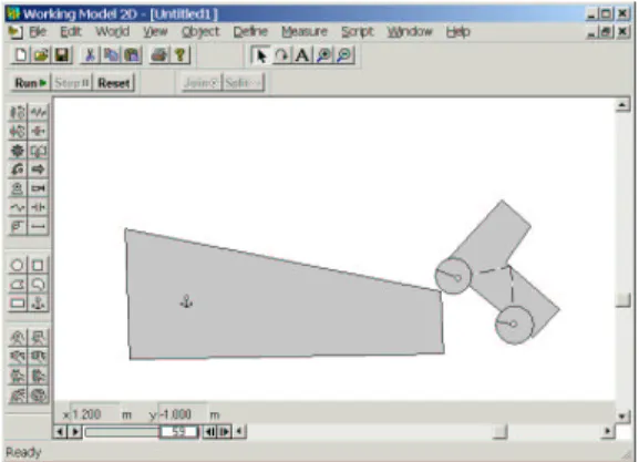
The system recognizes the various components in the drawing by their form and context; when the “Run” button is tapped, it transfers the design to a two-dimensional
mechani-Figure 3: The sketch simulated, showing the consequences. cal simulator which shows what will happen (Figure 3).1
Note that the user drew the device without using icons, menu commands, or other means of pre-specifying the com-ponents being drawn. Note, too, that there are ambiguities in the sketch, e.g., both the wheels of the car and pin joints are drawn using circles, yet the system was able to select the correct interpretation despite these ambiguities, by using the knowledge and techniques discussed below. The automatic disambiguation allowed the user to sketch without interrup-tion.
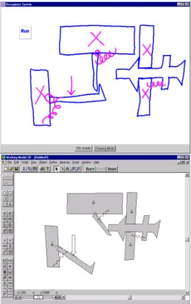
Figure 4 shows a session in which the user has drawn a more interesting device, a circuit breaker, and run a simula-tion of its behavior.
Note that ASSIST deals only with recognizing the me-chanical components in the drawing and is, purposely, literal-minded in doing so. Components are assembled just as the user drew them, and component parameters (e.g. spring con-stants, magnitudes of forces, etc˙) are set to default values. The car in Figures 1–3, for example, wobbles as it runs down the hill because the axles were not drawn in the center of the wheels. The combination of literal-minded interpretation and default parameter values can produce device behavior other than what the user had in mind. Other work in our group has explored the interesting and difficult problem of communicat-ing and understandcommunicat-ing the intended behavior of a device once it has been drawn using ASSIST [Oltmans, 2000].
3
Embedding Intelligent Assistance
We created a model for sketch understanding and ambigu-ity resolution inspired by the behavior of an informed human observer, one that recognizes the sketch by relying on both low-level (i.e., purely geometric) routines and domain spe-cific knowledge.
One interesting behavior of an informed observer is that in-terpretation begins as soon as the designer begins sketching. While not a required strategy—people can obviously interpret a finished sketch—there are advantages in ease of use and in speed from having the program do its interpretation in par-allel with drawing. Ease of use arises because the program
1
We use Working Model 2D from Knowledge Revolution, a commercial mechanical simulator; any simulator with similar ca-pabilities would do as well.
Figure 4: A sketch of a circuit breaker (left) and its simulation (right).
can provide an indication of its interpretation of parts of the sketch as soon as they are drawn, making it easier for the user to correct a misinterpretation. Interpretation is faster because incremental interpretation effects a divide and conquer strat-egy: parts of the drawing interpreted correctly can provide useful context when interpreting parts drawn subsequently.2
A second interesting behavior of an informed observer is the ability to accumulate multiple interpretations and defer commitment. Consider for example the objects in Figure 5. Are the strokes in 5a going to become part of a ball and socket mechanism (5b), or are they the beginning of a gear (5c)? Committing too soon to one interpretation precludes the other. Hence interpretation must be capable of revision in the face of new information.
There is clearly a need to balance out the desire for in-terpretation occurring in parallel with drawing, and the need to avoid premature commitment. We discuss below how our system accomplishes this.
Third, while commitment should be deferred, it must of course be made eventually, and determining when to make that commitment is not easy. Timing information can assist. Consider the case of circles: Because circles are low-level structures, it is likely that they will be used in higher-level structures, as for example when a circle turns out to be part of a pulley system. One way of dealing with this is to use timing
2
The program also seems faster because it is working while the user is drawing, reducing the user’s wait.
(b) (c)
(a)
Figure 5: An example of ambiguity: The bold strokes in (b) and (c) are identical to the strokes in (a).
data: the system gets to “watch” the sketch being drawn and knows when each stroke was made. If, some time after the circle has been drawn, it has still not been used in any other structure, the observer can plausibly guess that it will not be incorporated into another piece and should be interpreted as an independent circular body.3
Finally, parts may remain ambiguous even when a piece of the drawing is finished. To resolve these residual ambiguities, the observer uses his knowledge of mechanical engineering components and how they combine. Consider, for example, the small circles inside the larger circles in Figure 2; ASSIST determines that these are more likely to be pivot joints than additional circular bodies, both because small circles typi-cally indicate pin joints and because bodies do not typitypi-cally overlap without some means of interconnection (i.e., the pin joint).
Our system incorporates each of these observations: it be-gins interpreting the sketch as soon as the user starts draw-ing; it accumulates multiple interpretations, deferring com-mitment until sufficient evidence (e.g., stroke timing) accu-mulates to suggest a component has been finished, and it re-solves ambiguities by relying on knowledge from the domain about how components combine.
4
ASSIST’s Interpretation and
Disambiguation Process
ASSIST’s overall control structure is a hierarchical template-matching process, implemented in a way that produces con-tinual, incremental interpretation and re-evaluation as each new stroke is added to the sketch. Each new stroke triggers a three stage process of recognition, reasoning and resolu-tion. Recognition generates all possible interpretations of the sketch in its current state, reasoning scores each interpreta-tion, and resolution selects the current best consistent inter-pretation. After each pass through the three stages the sys-tem displays its current best interpretation by redrawing the sketch.
4.1
Recognition
In the recognition stage, ASSIST uses a body of recognizers, small routines that parse the sketch, accumulating all possible
3
A body is any hunk of material not otherwise interpreted as a more specialized component (like a spring, pin joint, etc.). The car body is a polygonal body; its wheels are circular bodies.
interpretations as the user draws each stroke. A recognizer takes as input raw strokes and previously recognized objects, and if the input fits its template, produces a new object. For example, the circle recognizer reports a circle if all the points on a stroke lie at roughly the same distance from the average X and Y coordinate of the stroke.4The circle is then available
to other recognizers, e.g., the pulley recognizer.
4.2
Reasoning
In the second stage the system scores each interpretation us-ing a variety of different sources of knowledge that embody heuristics about how people draw and how mechanical parts combine.
Temporal Evidence
People tend to draw all of one object before moving to a new one. Our system considers interpretations that were drawn with consecutive strokes to be more likely than those drawn with non-consecutive strokes.
Additional evidence comes from “longevity:” the longer a figure stays unchanged, the stronger its interpretation be-comes, because as time passes it becomes more likely that the figure is not going to be turned into anything else by ad-ditional strokes.
Simpler Is Better
We apply Occam’s razor and prefer to fit the fewest parts pos-sible to a given set of strokes. For example, any polygonal body (e.g., the car body in Figure 2) could have been inter-preted as a set of (connected) individual rods, but the system prefers the interpretation “body” because it fits many strokes into a single interpretation.
More Specific is Better
Our system favors the most specific interpretation. Circles, for example, (currently) have three interpretations: circular bodies, pin joints, and the “select” editing gesture. The se-lection gesture is the most specific interpretation, in the sense that every circle can be a circular body or pin joint, but not every circle can be a selection gesture (e.g., if it does not encircle any objects). Hence when a circle contains objects inside of it, the system prefers to interpret it as a selection gesture.
Domain Knowledge
ASSIST uses basic knowledge about how mechanical com-ponents combine. For example, a small circle drawn on top of a body is more likely to be a pin joint than a circular body.
User Feedback
User feedback also supplies guidance. The “Try Again” but-ton (see the bottom of Figure 1) permits the user to indicate that something was recognized incorrectly, at which point the system discards that interpretation and offers the user an or-dered list of alternative interpretations. Conversely the sys-tem can be relatively sure an interpretation is correct if the user implicitly accepts it by continuing to draw.
4
In other work we describe recognizers that use more sophisti-cated early processing of basic geometry [Sezgin, ].
Combining Evidence
The heuristics described above all independently provide ev-idence concerning which interpretation is likely to be correct. Our method of combining these independent sources involves distinguishing between two categories of evidence: categori-cal and situational.
Categorical evidence ranks interpretations relative to one another based on the first four knowledge sources described above. Each source is implemented in the system as a set of rules that takes two interpretations as input, and outputs an ordering between them. In processing Figure 1, for exam-ple, the interpretation “body” is ranked higher than the inter-pretation “connected rods,” based on the “Simpler is Better” heuristic.
Situational evidence comes from implicit and explicit feed-back from the user. Explicit feedfeed-back is provided by use of the “Try Again” button; implicit feedback arises when the user keeps drawing after the system displays an interpreta-tion, suggesting that the user is satisfied that the system has understood what has been drawn so far.
The system gives each interpretation two numeric scores, one from each category of evidence. The categorical score is an integer from 0 to 10; the situational score is an integer from -11 to 11. These values are chosen so that the situa-tional dominates the categorical, because we want user feed-back to dominate general ranking rules. An interpretation’s total score is simply the sum of its two scores.
To convert categorical evidence to a numerical score (so it can be combined it with the situational score), we generate a total ordering of all the interpretations consistent with the partial orders imposed by the categorical evidence. We do a topological sort of the graph of partial orders produced by the evidence and distribute scores evenly, from 0 to 10, over all the interpretations in the sorted graph.5
Situational scores start out at 0 and are strengthened or weakened by evidence that can raise of lower the current value by 1 or by 11. Situational evidence thus either mod-ifies an interpretation’s value by a small amount (1 unit) or declares it to be certainly correct or certainly incorrect. The system declares an interpretation to be certainly correct or certainly incorrect when the user explicitly accepts or rejects the interpretation using the “Try Again” dialog box. The sys-tem strengthens an interpretation by a small amount each time strokes added by the user are consistent with that interpreta-tion.6
We developed this approach to accumulating and combin-ing evidence, and implemented our knowledge sources as a rule based system, in order to provide a degree of modularity
5
The system first removes cycles in the graph by collapsing strongly connected components. Conceptually, this step indicates that the system will give an equal score to all interpretations that have inconsistent ordering given the evidence (i.e., one rule says A is more likely than B, while another says B is more likely than A). In addition, if there are more than 11 interpretations, the top ten are assigned scores of 10 through 1; the remaining interpretations all receive a score of 0.
6
The system does not yet weaken an interpretation by a small amount; we have included this possibility for symmetry and possible future use.
rod rod rod rod A B 1 1 1 2 2 3 3 3 4 4 5 3 1 2 2
Figure 6: A recognition graph for four strokes; scores are shown at the left of each interpretation.
to the system. Our overall approach to the problem is to take into account as many sources of knowledge as prove useful in interpreting the sketch. We knew that it would be impossible to identify and implement them all at the outset, hence our design put a high premium on the ability to add and remove sources of evidence easily.
4.3
Resolution
The third stage in the interpretation process involves deciding which interpretation is currently the most likely. Our system uses a greedy algorithm, choosing the interpretation with the highest total score, eliminating all interpretations inconsistent with that choice, and repeating these two steps until no more interpretations remain to be selected.
The process is illustrated by the interpretation graph in Fig-ure 6, which shows in graphical form all of the possible in-terpretations of four strokes (the top row of ovals): 4 separate lines, 4 rods, a quadrilateral, rectangle, or square. The rod on the left has the highest score, so it is chosen as a correct interpretation for stroke A. Choosing that interpretation elim-inates the interpretations of quadrilateral, rectangle or square, because stroke A is needed in any of these interpretations. In this context the other strokes are interpreted as rods because that interpretation has the highest score of any remaining in-terpretation.
Recall that our interpretation process is continuous: all three stages of processing occur after every new stroke is added to the sketch, and the current best interpretation as se-lected by the greedy algorithm is presented to the user. The process tends to settle down reasonably quickly, in part be-cause, as noted, we reward longevity. Hence once an interpre-tation has been presented to the user and unchanged for some period of time, it becomes increasingly unlikely to change.
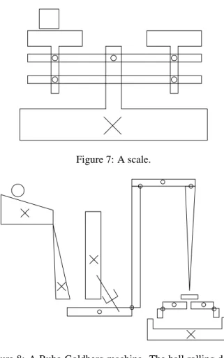
Figure 7: A scale.
Figure 8: A Rube-Goldberg machine. The ball rolling down the incline sets in motion a sequence of events that eventu-ally pushes the block at the right into the receptacle at bot-tom right. The device is an adaptation of the one found in [Narayanan, 1995].
5
Evaluation and Results
Our initial evaluation of ASSIST has focused on its natu-ralness and effectiveness. We asked subjects to sketch both on paper and using ASSIST. We observed their behavior and asked them to describe how ASSIST felt natural and what was awkward about using it.
We tested the system on eleven people from our the labo-ratory, two of whom had mechanical engineering design ex-perience. All were asked first to draw a number of devices on paper (Figures 7, 8, 9), to give them a point of compari-son and to allow use to observe differences in using the two media.
They were then asked to draw the same systems using AS-SIST (they drew with a Wacom PL-400 tablet, an active ma-trix LCD display that allows users to sketch and see their strokes appear directly under the stylus). We asked them how often they felt the system got the correct interpretation and how reasonable the misinterpretations were, and asked them to compare using our system to drawing on paper and to using a menu-based interface.
The system was successful at interpreting the drawings de-spite substantial degrees of ambiguity, largely eliminating the
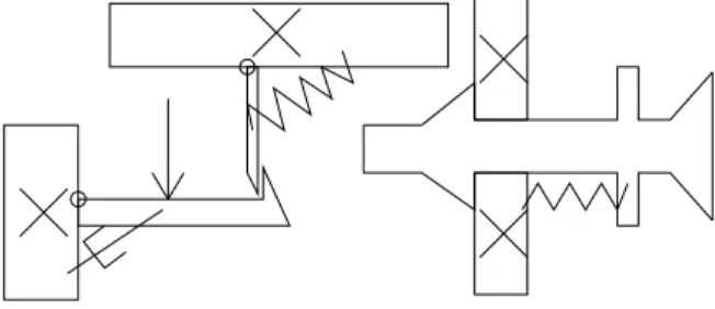
Figure 9: A circuit breaker.
need for the user to specify what he was drawing. As a con-sequence, a user’s drawing style appeared to be only mildly more constrained than when drawing on paper.
People reported that the system usually got the correct in-terpretation of their sketch. Where the system did err, ex-amination of its performance indicated that in many cases the correct interpretation had never been generated at the recogni-tion step, suggesting that our reasoning heuristics are sound, but we must improve the low-level recognizers. This work is currently under way.
Users tended to draw more slowly and more precisely with ASSIST than they did on paper. The most common com-plaint was that it was difficult to do an accurate drawing be-cause the system changed the input strokes slightly when it re-drew them (to indicate its interpretations). Users felt that the feedback given by ASSIST was effective but at times in-trusive. Our next generation of the system leaves the path of the strokes unchanged, changing only their color to indicate the interpretation.
For a more complete discussion responses to the system from a user interface perspective, see [Alvarado and Davis, 2001].
6
Related Work
The Electronic Cocktail Napkin (ECN) project [Do and Gross, 1996; Gross, 1996] attacks a similar problem of sketch understanding and has a method for representing ambiguity. Our system takes a more aggressive approach to ambiguity resolution and as a result can interpret more complicated in-teractions between parts. In order for ECN to to resolve am-biguity, the user must either inform the system explicitly of the correct interpretation, or the system must find a specific higher-level pattern that would provide the context to disam-biguate the interpretation of the stroke. Our system, in con-trast, takes into account both drawing patterns and knowledge of drawing style.
[Mankoff et al., 2000] presents a general framework for representing ambiguity in recognition-based interfaces. This work is similar in using a tree-like structure for representing ambiguity, but touches only briefly on ambiguity resolution. Our work pushes these ideas one step further within the do-main of mechanical engineering by providing a framework and set of heuristics for ambiguity resolution.
SILK [Landay and Myers, 2001] allows a user to sketch out rough graphical user interface designs, then transform them into more polished versions. SILK addresses the notion of
ambiguity, but limits its handling of it to single parts, e.g., is this group of strokes a radio button or a check box? This does not in general affect the interpretation of the other strokes in the sketch. In contrast, our system can resolve ambiguities that affect the interpretation of many pieces of the sketch.
A theoretical motivation to our work was provided by work in [Saund and Moran, 1995], which outlines several goals in interpreting ambiguous sketches. Our work implements many of the multiple representation and disambiguation tech-niques suggested in their work.
We have also been motivated by work in mechanical sys-tem behavior analysis, especially in the field of qualita-tive behavior extraction and representation [Sacks, 1993; Stahovich et al., 1998]. The work by Stahovich aims to extract the important design constraints from the designer’s rough sketch and is less focused on the interface or sketch recognition process. It was nevertheless the inspiration for our work in this area.
7
Future Work
The work presented in this paper is a first step toward creating a natural interface. It can usefully be expanded in several areas.
First, our current formulation of recognition and evidential reasoning is of course quite informal. This is a consequence of our focus at this stage on the knowledge level, i.e., trying to determine what the program should know and use to evaluate interpretations. Once the content has become more stable and better understood, a more formal process of evaluation and control (e.g., Bayes’ nets) may prove useful both for speed and scaling.
Second, in our efforts to combine the best properties of paper and the digital medium we have yet to find many of the appropriate trade-off points. How aggressive should the system be in its interpretations? Forcing the user to correct the system immediately when it makes a mistake greatly aids recognition, but may distract the designer by forcing her to focus on the system’s recognition process rather than on the design. In addition, some ambiguities are resolved as more of the sketch is drawn, yet if the system waits for the sketch to be finished, unraveling an incorrect interpretations can be a great deal of work.
In the same vein, it will be important to calibrate how im-portant true freehand sketching is to designers. The obvious alternative is a icon-based system with graphical editing capa-bilities (e.g., moving and resizing the standard components). Freehand drawing can be powerful, but alternative interface styles need to be considered as well.
The system should also adapt to new users and their sketch-ing style. For example, one of our heuristics was that people draw all of one object before moving onto the next, but there are of course exceptions. The system should be able to ad-just to this type of behavior and learn to override its default heuristic.
8
Conclusion
CAD systems are rarely used in early design because they do not allow for quick and natural sketching of ideas. To be
useful here, computers must allow the designer to sketch as on paper, yet provide benefits not available with paper, such as the ability to simulate the system.
To provide an interface that feels natural yet interprets sketches as the user draws, the system must be able to re-solve ambiguities without interrupting the user. This work provides one solution to problem of ambiguity resolution in a framework of reasonable generality.
Acknowledgments
Luke Weisman and Mike Oltmans helped extensively in the development of these ideas and this system. The work was supported in part by the National Science Foundation, the MIT/Ford Motor Company Collaboration, and MIT’s Project Oxygen.
References
[Alvarado and Davis, 2001] Christine Alvarado and Randall Davis. Preserving the freedom of sketching to create a natural computer-based sketch tool. In Human Computer
Interaction International Proceedings, 2001.
[Do and Gross, 1996] Ellen Yi-Luen Do and Mark D. Gross. Drawing as a means to design reasoning. AI and Design, 1996.
[Gross and Do, 1996] Mark Gross and Ellen Yi-Luen Do. Ambiguous intentions: a paper-like interface for creative design. In Proceedings of UIST 96, pages 183–192, 1996. [Gross, 1995] Mark D. Gross. Recognizing and interpreting diagrams in design. In 2nd Annual International
Confer-ence on Image Processing, pages 308–311, 1995.
[Gross, 1996] Mark D. Gross. The electronic cocktail napkin - a computational environment for working with design di-agrams. Design Studies, 17:53–69, 1996.
[Hearst, 1998] Marti Hearst. Sketching intelligent systems.
IEEE Intelligent Systems, pages 10–18, May/June 1998.
[Landay and Myers, 2001] James A. Landay and Brad A. Myers. Sketching interfaces: Toward more human inter-face design. IEEE Computer, 34(3):56–64, March 2001. [Mankoff et al., 2000] Jennifer Mankoff, Scott E Hudson,
and Grefory D. Abowd. Providing intergrated toolkit-level support for ambiguity in recogntiion-based interfaces. In
Proceedings of the CHI 2000 conference on Human fac-tors in computing systems, pages 368–375, 2000.
[Narayanan et al., 1995] N. Hari Narayanan, Masaki Suwa, and Hiroshi Motoda. Behavior Hypothesis from Schematic
Diagrams, chapter 15, pages 501–534. The MIT Press,
Cambridge, Massachusetts, 1995.
[Oltmans, 2000] Michael Oltmans. Understanding natually conveyed explanations of device behavior. Master’s thesis, Massachusetts Institute of Technology, 2000.
[Rubine, 1991] Dean Rubine. Specifying gestures by exam-ple. Computer Graphics, pages 329–337, July 1991. [Sacks, 1993] Elisha Sacks. Automated modeling and
kine-matic simulation of mechanisms. Computer-Aided Design, 25(2):107–118, 1993.
[Saund and Moran, 1995] Eric Saund and Thomas P. Moran. Perceptual organization in an interactive sketch editing ap-plication. In ICCV 1995, 1995.
[Sezgin, ] Metin Sezgin. Early processing in sketch under-standing. Unpublished Master’s Thesis, Massachusetts In-stitute of Technology.
[Stahovich et al., 1998] T. Stahovich, R. Davis, and H.Shrobe. Generalting multiple new designs from a sketch. Artificial Intelligence, 104(1-2):211–264, 1998. [Ullman et al., 1990] David G. Ullman, Stephan Wood, and
David Craig. The importance of drawing in mechanical design process. Computer & Graphics, 14(2):263–274, 1990.