TRACKING PERFORMANCE OF GPS RECEIVERS WITH MORE
THAN ONE MULTIPATH
Christophe MACABIAU, Benoît ROTURIER, Abdelahad BENHALLAM CNS Research Laboratory of the ENAC,
ENAC, 7 avenue Edouard Belin, BP 4005, 31055 TOULOUSE CEDEX 4, France [email protected]
ABSTRACT
A wide majority of studies on the effect of multipath focused on the analysis of the code and phase tracking errors when only two rays enter the tracking loops, namely the direct ray plus one diffracted ray. Unfortunately, this condition does not correspond to the most frequent situations, where the received signal can be the discrete sum of several powerful replicas of the direct signal. The aim of this paper is to present the theoretical results of a study that identifies the performance of the GPS receivers in the case where more than two powerful rays enter the tracking loops. The theoretical analysis shows that in the case of continuous tracking, if the summed amplitudes of the reflected signals is lower than the amplitude of the direct signal, the code error envelope of the composite signal can be approximated as the sum of the code error envelope for each individual ray, except in its transition zones. The distortion in these zones is negligible for the narrow correlator DLLs and the DLLs controlled by linear combinations of correlation values.
I. INTRODUCTION
The tracking performance of the GPS receivers is highly degraded when the received signal is affected by multipath propagation. A large number of studies on the effect of multipath on the code and phase tracking errors were carried out, as summarized in [Braasch, 1996].
Several studies led to the implementation of specific structures designed to reduce the multipath induced errors, like the Narrow Correlator receiver [Fenton et al, 1991], [Van Dierendonck et al, 1992], the Multipath Estimating Delay Lock Loop (MEDLL) [Van Nee, 1994], [Townsend et al., 1995], the Multipath Elimination Technology (MET) [Townsend et al., 1994], Strobe and Edge correlators [Garin et al., 1996], Early1-Early2 Tracker [Mattos, 1996], Multipath Mitigator Types A and B [Hatch et al., 1997], Compensated Correlators [Doris, 1997], Enhanced Strobe correlator [Garin et al., 1997] and Gated and High Resolution Correlators (HRC) [McGraw et al., 1999].
The performance of the proposed techniques is publicly advertised by plotting the code and phase tracking error envelopes as a function of the relative delay of the reflected signal with respect to the direct signal. Therefore, the end user may only know the maximum magnitude of the synchronization errors when only two rays enter the tracking loops, namely the direct ray plus one diffracted ray.
Unfortunately, this condition does not correspond to the most frequent situations, where the received signal can be the discrete sum of several powerful replicas of the direct signal. For example, the antenna can be hit by the RHCP line-of-sight signal coming from the satellite, the LHCP signal reflected off the ground, and several RHCP signals scattered by a set of buildings and the ground.
This paper presents the main theoretical results of a study that aims at determining the performance of the GPS receivers when the signal is affected by several multipath. It is often thought that the effect of several multipath may be extrapolated from the two-ray envelope error curve by a
not clear if this linear superposition is really valid.
Here, we first present the theoretical analysis that was performed, and some resulting tracking error envelopes obtained through analytical determination and by simulation. Finally, we discuss the validity of the linear superposition above mentioned.
.
II. MEASUREMENT MODELS
The C/A signal entering the tracking loops is the RF signal sensed by the antenna, fed to the RF unit where it is filtered, amplified, down-converted to intermediate frequency, sampled and quantized. This incoming composite C/A signal is modeled as follows:
(
( )) (
( )) (
cos 2 ( ))
( ) ) ( ) ( 0 0 k n k kT f k kT C k kT D k A k V N f e i e i f i i e − i − − + = = τ τ π θ (1) where• k is the discrete time index and Te is the internal sampling period of the receiver.
• f0 is the intermediate frequency of the receiver.
• N+1 is the total number of replicas entering the loops. The line-of-sight signal is denoted with subscript 0.
• Ai is the amplitude of each replica, and D is the P/NRZ/L navigation message.
• Cf is the C/A code as filtered by the RF unit, and nf is the filtered additive noise.
• τi and θi are respectively the total group and phase propagation delays of each ray.
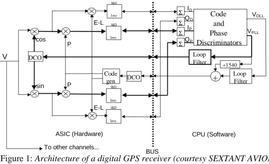
The operations performed by the tracking loops called the Phase Lock Loop (PLL) and the Delay Lock Loop (DLL) are illustrated in figure 1 for a classical receiver. The aim of these tracking loops is to generate local replicas of the code and carrier that are synchronized with the line-of-sight signal. To achieve these objectives, the loops control local oscillators whose outputs are continuously compared with the incoming signal. The signals used to control the oscillators are filtered versions of the discrimination signals. These discrimination signals are non linear functions of the digital I and Q data delivered by the Integrate and Dump filters that cumulate M input samples.
Figure 1: Architecture of a digital GPS receiver (courtesy SEXTANT AVIONIQUE). For example, the discrimination function of the classical dot-product DLL is proportional to:
2 2 ) ( P P P D P D DLL Q I Q Q I I k V EL E L + + = − − (2) DCO Code gen DCO ms 1 ms 1 ms 1 I&D I&D I&D ms 1 I&D Σ Σ Σ Σ Code and Phase Discriminators QP IP ID QD E-L E-L P P Loop Filter Loop Filter ÷1540 +
ASIC (Hardware) CPU (Software)
V cos sin BUS VDLL VPLL To other channels...
where î í ì − − − − − − − − − − = − − − − − − − − − − = = = ∆ ∆ ∆ ∆ − − M m e e e D M m e e e D k T m k C k T m k C k T m k f m k V k Q k T m k C k T m k C k T m k f m k V k I L E L E 0 0 0 0 ] ) ) ] ) ) 2 2 2 2 ) ( ˆ ) (( ) ( ˆ ) (( ))[ ( ˆ ) ( 2 sin( ) ( ) ( ) ( ˆ ) (( ) ( ˆ ) (( ))[ ( ˆ ) ( 2 cos( ) ( ) ( τ τ θ π τ τ θ π (3) and
(
)
(
)
î í ì − − − − − = − − − − − = = = ) ( ˆ ) ( )) ( ˆ ) ( 2 sin( ) ( ) ( ) ( ˆ ) ( )) ( ˆ ) ( 2 cos( ) ( ) ( 0 0 0 0 k T m k C k T m k f m k V k Q k T m k C k T m k f m k V k I e M m e P M m e e P τ θ π τ θ π (4)In these expressions, τˆand θˆ are the code and carrier phase delay estimates that have to be applied to the local oscillators in order to cancel the discrimination function.
It can be shown that this discrimination function has the following expression when the incoming signal is the noise free signal modeled as in (1):
(
)
(
)
( )[ ( ) ( )]cos(
))
) , ( 2 2 0 0 0 0 D D i D i i j N i e i e j N j i j DLL k AAD kT D kT R R R V j ε τ ε τ θ θ ε τ τ − +∆ − − +∆ + − − = ∆ ∆ ∆ = = (5) where • εD =τi −τˆi is the deviation between the group delay of ray i and the code delay estimate.
• ∆ is the early-late chip spacing.
Another interesting example is a DLL controlled by a linear combination of several correlation points, as in the Strobe correlator, the MET, or the HRC. For example, if the reference waveform of the DLL is the weighted sum of two sets of Early minus Late correlators spaced ∆1 and ∆2 apart, the
discrimination function is:
) , ( ) , ( ) (k =V k ∆1 +aV k ∆2 VDLL DLL DLL (6)
The code and phase tracking errors, εD0and εP0, are the deviations between the true group and phase propagation delays of the direct signal, τ0 and θ0, and their corresponding estimates τˆand θˆ .
III. CODE TRACKING ERRORS
If several replicas of the direct signal enter the tracking loops, the quality of the code and phase tracking operations can be severely degraded, and in some cases of destructive collaboration between all the multipath, the loops may even lose lock for some instants.
For a classical Early minus Late DLL including narrow correlator DLLs, if the receiver maintains continuous tracking, if the direct signal is never blocked, and if the sum of the amplitudes of each reflected signal inside the DLL is lower than the amplitude of the direct signal, then the code tracking error is bounded by half the Early minus Late chip spacing. This result is explained by the fact that the Early minus Late loop is not sensitive to any deformation of the correlation peak outside of its exploration interval.
If the sum of the amplitudes of each reflected signal is larger than the amplitude of the direct signal, then the code tracking error may be much larger than half the Early minus Late chip spacing, as the multipath signals may cooperate to build a correlation peak far away from the direct signal correlation peak. This case can not be analyzed in detail in this paper and it will be presented later.
The extreme values of the code tracking errors are obtained in two distinct cases:
• when the direct signal and all the reflected signals are in phase
• when each of the reflected signals is out of phase with respect to the direct signal.
For short delays and powerful multipath, the absolute maximum magnitude of the phase tracking error is the product of λ/4 by the number of rays entering the PLL. However, the phase
envelopes.
Figure 3 shows the envelope of the code tracking error for a 0.1 Tc narrow correlator, in the
case where the signal is the sum of the line-of-sight signal plus two reflected signals. This figure was plotted using theoretical expressions obtained using (5), assuming the C/A code autocorrelation function is an ideal triangle function, and assuming the pre-correlation bandwidth is infinite. As we can see in this figure, the shape of the code tracking error envelope can be divided in four main regions. The first region corresponds to the case where both rays combine to induce non-zero tracking errors, and the resulting envelope is the box visible in the foreground. Its height is the sum of the maximum tracking errors induced by each ray. The second region is the domain where both rays have a relative delay larger than Tc+∆/2, therefore not influencing the DLL any more. The third and fourth regions are the regions where one of the ray has gone out of the area of influence of the DLL, and only remains the tracking error due to the closest ray.
Figure 4 shows the envelope of the code tracking error for a 0.1 Tc – 0.05 Tc linear
combination DLL obtained using (6), in the same case as previously. As this type of loop is solely influenced by multipath having short and chip range delays, only three small non-zero regions exist. The first non-zero region corresponds to the case where at least one of the rays has a short delay. In that case, the maximum tracking error is approximately the sum of the maximum tracking error induced by each ray. The second and third non-zero regions are the regions where at least one of the rays has a delay close to one chip, and the maximum tracking error of each individual ray can be summed, except if one of the rays has a short delay.
Figure 3: Code tracking error envelope for 2 reflected rays with a total amplitude < LOS amplitude (0.1 Tc narrow correlator DLL).
Figure 4: Code tracking error envelope for 2 reflected rays with a total amplitude < LOS amplitude (0.1 Tc-0.05 Tc DLL).
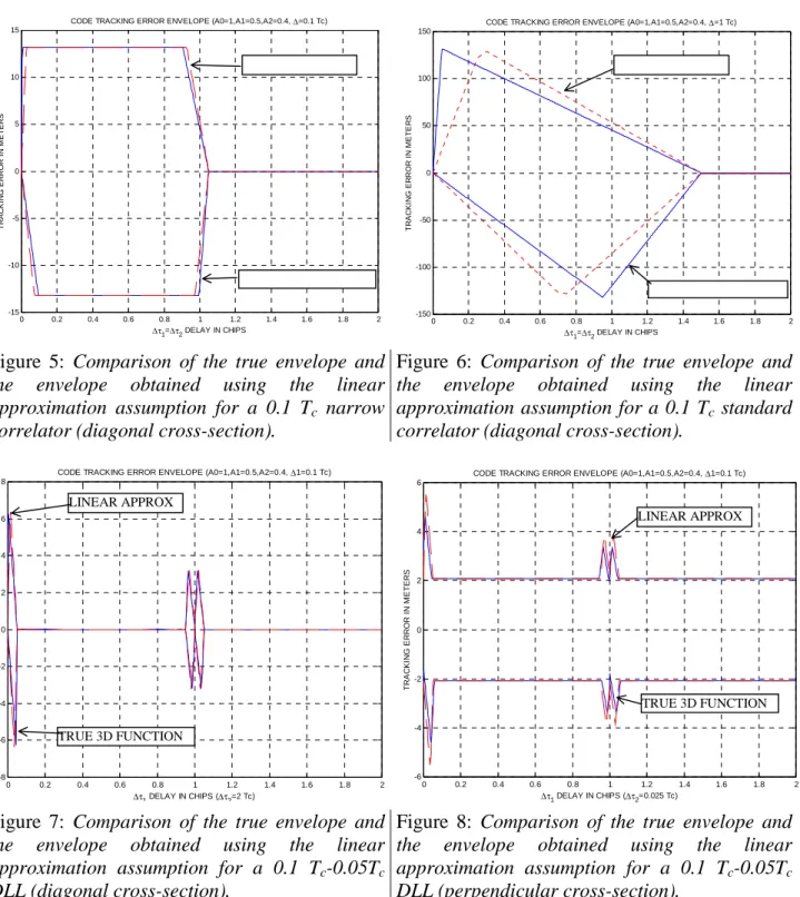
As introduced previoulsy, in most of the situations, these envelopes coincide with the sum of the single envelopes obtained for each individual ray, except in their transition zones. For a narrow correlator receiver, this happens when the relative delays are close to 0 or 1 chip, as we can see in the diagonal cross section presented in figure 5. For a standard 1 chip spacing correlator, the deviation with respect to the linear addition assumption is significant, as illustrated in figure 6.
For a DLL controlled by a reference signal that is a linear combination of two Early-Late signals, the deviation between the true theoretical 3D function and the linear approximation is less severe, as illustrated in figures 7 and 8.
Figure 5: Comparison of the true envelope and the envelope obtained using the linear approximation assumption for a 0.1 Tc narrow
correlator (diagonal cross-section).
Figure 6: Comparison of the true envelope and the envelope obtained using the linear approximation assumption for a 0.1 Tc standard
correlator (diagonal cross-section).
Figure 7: Comparison of the true envelope and the envelope obtained using the linear approximation assumption for a 0.1 Tc-0.05Tc
DLL (diagonal cross-section).
Figure 8: Comparison of the true envelope and the envelope obtained using the linear approximation assumption for a 0.1 Tc-0.05Tc
DLL (perpendicular cross-section).
IV. CONCLUSION
This paper shows the theoretical results of an analysis that aims at determining the performance of GPS receivers tracking a signal degraded by more than one multipath. The results presented here focused on the code tracking error envelopes when the sum of the amplitudes of the reflected signal is lower than the amplitude of the line-of-sight signal.
We show that when the incoming signal is composed of the direct signal and several replicas of this signal, the code tracking error envelope can be approximated as the sum of the code tracking error envelopes expected for each individual ray, except in the transition zones of these envelopes.
LINEAR APPROX TRUE 3D FUNCTION LINEAR APPROX TRUE 3D FUNCTION 0 0.2 0.4 0.6 0.8 1 1.2 1.4 1.6 1.8 2 -6 -4 -2 0 2 4 6 ∆τ1 DELAY IN CHIPS (∆τ2=0.025 Tc) T R AC KI N G ER R O R IN M E T E R S
CODE TRACKING ERROR ENVELOPE (A0=1,A1=0.5,A2=0.4, ∆1=0.1 Tc)
0 0.2 0.4 0.6 0.8 1 1.2 1.4 1.6 1.8 2 -8 -6 -4 -2 0 2 4 6 8 ∆τ1 DELAY IN CHIPS (∆τ2=2 Tc) T RA C K ING E R RO R IN M E T E RS
CODE TRACKING ERROR ENVELOPE (A0=1,A1=0.5,A2=0.4, ∆1=0.1 Tc)
0 0.2 0.4 0.6 0.8 1 1.2 1.4 1.6 1.8 2 -15 -10 -5 0 5 10 15 ∆τ1=∆τ2 DELAY IN CHIPS T R AC KIN G ER R O R I N M E T E R S
CODE TRACKING ERROR ENVELOPE (A0=1,A1=0.5,A2=0.4, ∆=0.1 Tc)
0 0.2 0.4 0.6 0.8 1 1.2 1.4 1.6 1.8 2 -150 -100 -50 0 50 100 150 ∆τ1=∆τ2 DELAY IN CHIPS TR AC KI N G ER R O R I N M E T E R S
CODE TRACKING ERROR ENVELOPE (A0=1,A1=0.5,A2=0.4, ∆=1 Tc)
TRUE 3D FUNCTION
TRUE 3D FUNCTION LINEAR APPROX
narrow correlator receiver for the maximum expected code tracking errors, but the approximation error is highly degraded when the correlator spacing is widened.
In the case of a DLL controlled by a linear combination of correlation values, the approximation error in the transition zones is also small, if the chip spacings used are narrow.
The next results to be presented are the phase tracking error envelopes for these receiver structures, and the code and phase tracking errors for other structures. In addition, we will present the characteristics of the code tracking error when the sum of the amplitudes of the reflected signals is larger than the amplitude of the direct signal, and the measured code and phase tracking error envelopes using a signal generator.
ACKNOWLEDGMENTS
The authors wish to thank the STNA for supporting this research, and SEXTANT AVIONIQUE for having provided technical assistance. In addition, Redouane Yazid deserves our thanks for helping us performing this study.
REFERENCES
Braasch M. (1996) « Global Positioning System: Theory and Applications », volume 1,
chapter ‘Multipath Effects’, pages 547-568, AIAA.
Doris D. (1997) “ Modélisation de récepteurs GPS. Application à l’étude de l’influence des
multitrajets sur les performances du récepteur L1 GPS”, Thèse INPT, Septembre.
Fenton P., Falkenberg B., Ford T., Ng K. and Van Dierendonck A.J. (1991) « NovAtel’s
GPS Receiver – the High Performance OEM Sensor of the Future », proceedings of ION GPS-91, Albuquerque, Sept 9-13.
Garin L., Van Diggelen F. and Rousseau J.M. (1996) “Strobe and Edge Correlator
Multipath Mitigation for Code”, proceedings of ION GPS-96, Kansas City, September 17-20.
Garin L. and Rousseau J.M. (1996) “Enhanced Strobe Correlator Multipath Rejection for
Code and Carrier”, proceedings of ION GPS-97, Kansas City, September 16-19.
Hatch R., Keegan R. and Stansell T. (1997) “Leica’s Code and Phase Multipath Mitigation
Techniques”, proceedings of ION National Technical Meeting, Santa Monica, January 14-16.
Mattos P. (1996) “Multipath Elimination for the Low-Cost Consumer GPS”, proceedings of
ION GPS-96, Kansas City, September 17-20.
McGraw G. and Braasch M. (1999) “GNSS Multipath Mitigation Using Gated and High
Resolution Correlator Concepts”, proceedings of ION National Technical Meeting, San Diego, January 25-27.
Townsend B. and Fenton P. (1994) “A Practical Approach to the Reduction of Pseudorange
Multipath Errors in a L1 GPS Receiver”, proceedings of ION GPS-94, Salt Lake City, September 20-23.
Townsend B., Van Nee R., Fenton P. and Van Dierendonck K. (1995) “Performance
Evaluation of the Multipath Estimating Delay Lock Loop”, proceedings of ION National Technical Meeting, Anaheim, January 18-20.
Van Dierendonck A.J., Fenton P. and Ford T . (1992) « Theory and Performance of
Narrow Correlator Spacing in a GPS Receiver », proceedings of ION National Technical Meeting, San Diego, January 27-29.
Van Nee R., Siereveld J., Fenton P. and Townsend B. (1994) « The Multipath Estimating
Delay Lock Loop : Approaching Theoretical Limits », proceedings of IEEE PLANS 94, Las Vegas, April 11-15.