Investigating parallel multi-step vibration processing
pipelines for planetary stage fault detection in wind
turbine drivetrains
Sofia Koukoura1, C´edric Peeters2, Jan Helsen 2, James Carroll 1.
1University of Strathclyde, Glasgow, UK. 2
Department of Applied Mechanics, Vrije Universiteit Brussel, Brussels, Belgium. E-mail: [email protected]
Abstract. This paper proposes a signal processing approach for wind turbine gearbox
vibration signals based on employing multiple analysis pipelines. These so-called pipelines consist of combinations of various advanced signal processing methods that have been proven to be effective in literature when applied to wind turbine vibration signals. The performance of the pipelines is examined on vibration data containing different wind turbine gearbox faults in the planetary stages. Condition indicators are extracted from every pipeline to evaluate the fault detection capability for such incipient failures. The results indicate that the multipronged approach with the different pipelines increases the reliability of successfully detecting incipient planetary stage gearbox faults. The type, location, and severity of the fault influences the choice for the appropriate processing method combination. It is therefore often insufficient to only utilize a single processing pipeline for vibration analysis of wind turbine gearbox faults. Besides investigating the performance of the different processing techniques, the main outcome and recommendation of this paper is thus to employ a diversified analysis methodology which is not limited to a sole method combination, to improve the early detection rate of planetary stage gearbox faults.
1. Introduction
According to various reliability studies in the wind turbine literature, the gearbox is one of the most critical components in terms of maintenance. High downtimes and repair costs dominate gearbox failures, therefore it is important to efficiently monitor this component [1]. Condition monitoring systems enable the detection of faults at an early stage, which can reduce unplanned and unscheduled repair costs. Vibration signal analysis is the most predominantly used method for wind turbine drive train condition monitoring [2].
A wind turbine gearbox consists of different stages of gears and bearings. Considering this variety in components, their fault behaviour and the wide frequency range, different vibration analysis methods have been developed that address different faults, such as Time-Synchronous Averaging (TSA), Cepstrum and Envelope spectrum [3]. In order to optimally compress the abundance of information in time-domain vibration data, instead of using the data raw, features can be extracted from the signals that act as health indicators. Various gear fault detection
algorithms and condition indicators are analysed and compared in [4, 5]. A robust
This paper aims to propose several signal processing pipelines for wind turbine gearbox
vibration signals. Various advanced signal processing methods that have proven their
effectiveness in the vibration analysis literature are applied on wind turbine vibration signals. The paper is organised as follows; Section 2 gives a brief literature review of the state-of-the-art methods on wind turbine vibration signal processing, Section 3 outlines the signal processing pipelines, explaining each method used in the pipeline and giving some indicative examples on simulated vibration signals. Section 4 shows experimental results from the proposed pipelines, applied on data of operating wind turbines with confirmed gearbox faults. Results and key findings from the paper are summarised in the conclusions.
2. Literature Review
Vibration signal analysis is widely used for wind turbine condition monitoring. Typically, the components of a wind turbine consist of a main shaft, main bearing, gearbox, generator, nacelle,
tower and foundations [6]. A lot of focus has been placed on monitoring the gearbox and
generator, since these are the components with the highest downtime [1, 7]. Wind turbine gearboxes are usually planetary, having one low-speed planetary stage with two parallel stages or two planetary stages with one high-speed parallel stage. The main components of the gearbox include gears, bearings and shafts at the different stages and it is important to localise faults to a specific component level for supply chain reasons. Vibration sensors measuring acceleration are mounted on the casing of the gearbox, preferably close to the various stages, or at the bearings on either end. A tacho encoder can also be mounted to measure speed variation, usually it is then installed on the high speed shaft.
The first pre-processing step when it comes to wind turbine vibration signals is to remove speed varying effects. Wind speed varies with time and so the wind turbine gearbox operates under time-varying conditions. This can be solved using order tracking, which resamples the original vibration signal at a constant angle increment, converting the non-stationary time-domain signal into the stationary one in angular time-domain [8]. There are also tacho-less speed estimation methods and a recent review of seven different state-of-the-art techniques is given in [9].
Time-domain analysis generally involves rather straightforward indicator calculations on the time waveforms. Examples of commonly used monitoring indicators include root mean square (RMS), crest factor, peak-to-peak interval, standard deviation, skewness, and kurtosis. Successful results for the RMS indicator are presented in [10], but the signals were sampled at constant position intervals in a lab experiment. Time-synchronous averaging is a very commonly used technique and very effective in periodic component extraction from additive noises, such as isolating gear fault-related features from the gearbox vibrations [11].
Vibration-based condition monitoring practices often involve transformation of the signal to the frequency domain where fault periodicities can be distinguished more easily as compared to the time domain. The most common practice is spectrum analysis using the Fast Fourier Transform (FFT). Another common analysis domain is the cepstrum [12], which is capable of detecting harmonics and sideband patterns in the log-amplitude spectrum. The cepstrum is basically a “spectrum of a log-amplitude spectrum” and separates the input from its transfer
path. Identifying the increment in the magnitude and number of the fault characteristic
sidebands around the meshing frequency and its harmonics in the corresponding spectrum is another strategy which will help to realize gear fault diagnosis [13]. For bearing faults, the demodulation-based fault diagnosis strategy provides an effective detection manner because the fault characteristic frequency can be highlighted in the envelope spectrum with typically less spectral interfering content [11]. Previous work by the authors has demonstrated successful applications of an automated cepstrum editing procedure with envelope analysis on the NREL test rig [14].
Spectral Kurtosis (SK) [15] is another valuable tool for extracting transients buried in noise and for locating the frequency bands with a high amount of impulsiveness. This knowledge is then used to define a frequency filter to isolate the parts with maximal impulsiveness. SK depends on the choice of the Short Time Fourier Transform window length or on the bandwidth of the band-pass filter.The kurtogram has been proposed to solve this issue, which is a binary-ternary cascade of filters using different values of the STFT window length [16]. In a recent publication, a meshing frequency modulation index-based kurtogram is constructed to detect a planet bearing fault induced resonance frequency band without the help of health baseline [17]. The kurtosis-based algorithms are often very effective for bearing fault detection, due to the impulsive nature of that type of fault. Gear faults have also been detected through SK, with an example of a ring gear fault on a wind turbine planetary gearbox in [18] and the results seem to be more promising compared to TSA. In a comparative study by the authors though, SK did not seem to have such strong detecting capabilities on an intermediate shaft gear fault compared to a simple cepstrum and sideband analysis [5].
Given the large variety of signal processing methods and detection capabilities -especially on multi-component assets such as wind turbine gearboxes- it is challenging to find an algorithm that generalises successfully in all case studies and problems. Algorithm diversity is discussed in [4]. There is no single condition indicator that works for every gear or bearing fault, indicating that it is recommended to diversify the analysis. After all, in reality fault cases, the location of the fault will not be known. Therefore, various signal processing methods should be applied in parallel to raw vibration signals from wind turbines, in order to capture all possible fault locations and failure modes. Therefore, this paper proposes a framework of ten different parallel pipelines that can be applied on wind turbine vibration signals, with the aim of increasing algorithm variability and component detection capability of diagnostic procedures.
3. Methodology
This section presents a methodology for processing vibration signals measured on wind turbine
drivetrains. Industry practice usually involves collecting signals in the time domain and
analyzing them afterwards in the frequency domain after pre-processing. Some monitoring
systems have already basic embedded processing capabilities (e.g. Fast Fourier Transform)
to circumvent transmitting time domain signals. On many wind turbines, especially offshore, there are typically vibration sensors measuring acceleration at various stages of the gearbox and a speed encoder mounted on the high speed shaft. The methodology in this paper involves processing time domain signals using ten different analysis pipelines, that have all been proven in literature to have successful diagnostic capabilities for different drivetrain components. The ten pipelines can work in parallel and the end goal is to combine all results for decision making, which is out of scope for this paper. The scope of this paper is to focus more on the algorithms of the pipeline and demonstrate their effectiveness with respect to incipient faults.
The ten different signal processing pipelines include the following method combinations: (i) Angular resampling + binary-ternary filterbank + statistical indicators
(ii) Angular resampling + cepstrum editing + binary-ternary filterbank + statistical indicators (iii) Angular resampling + cepstrum editing + time-synchronous averaging + binary-ternary
filterbank + statistical indicators
(iv) Angular resampling + time-synchronous averaging + binary-ternary filterbank + statistical indicators
(v) Angular resampling + cepstrum editing + blind deconvolution filtering + envelope spectrum amplitude tracking
(vii) Angular resampling + envelope spectrum amplitude tracking (viii) Angular resampling + cepstrum amplitude tracking
(ix) Angular resampling + cepstrum editing + envelope spectrum amplitude tracking
(x) Angular resampling + cyclic spectral coherence 2D map + automated carrier frequency band selection + envelope peak amplitude tracking
These methods are explained further in the following subsections and an application on a simulated signal is shown to demonstrate their application.
3.1. Angular Resampling
Since wind turbines operate at a fluctuating rotation speed, vibration signals that are measured
on the drivetrain typically contain non-stationary signal content. The effect of the speed
fluctuation on the vibration signal needs to be compensated before moving on to further analysis since the majority of frequency-based analysis methods rely on the assumption of stationarity. To achieve this compensation, we transform the time domain signal to the angular domain using the rotation speed as measured by an angle encoder. If not available, the rotation speed can also be estimated directly from the vibration signal itself using a variety of techniques [9].
3.2. Cepstrum Editing
One potential step in the pipelines is the separation between deterministic and stochastic signal content [14, 19]. The former is more useful when analysing for gear faults due to the quasi-perfect periodic nature of gear vibrations, while the latter is primarily of interest when looking for bearing faults due to their quasi-cyclostationary behaviour which results from random slippage of the rolling elements. To achieve this separation, the automated cepstrum editing procedure (ACEP) is employed since it allows for an automated and reliable separation of these two components [14]. Alternatives to the ACEP method can include discrete/random separation (DRS) technique [20], self-adaptive noise cancellation (SANC) [21], linear prediction filtering (LP) [22], and the (generalized) time synchronous average (TSA) [23].
3.3. Filterbank Approach
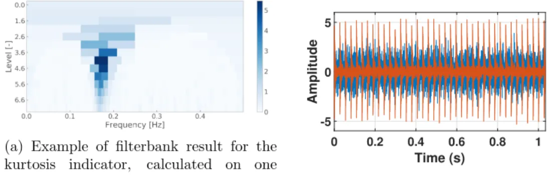
The binary-ternary filterbank approach is employed to increases the signal-to-noise ratio of potential fault signatures in localized frequency bands. In order to increase the signal-to-noise ratio of potential fault signatures, we apply different frequency filters on the processed signals to track the statistics in different frequency bands. The choice for the frequency filtering grid is chosen similar to the one defined for the Kurtogram [16], meaning a binary-ternary filter grid as shown in Fig. 1a for a simulated signal. This filter grid is thus used to process each signal and subsequently, each frequency band is tracked over time using multiple statistical indicators.
(a) Example of filterbank result for the
kurtosis indicator, calculated on one
vibration signal [16] 0 0.2 0.4 0.6 0.8 1 Time (s) -5 0 5 Amplitude
(b) Simulated time series Figure 1: Filterbank example and time series
3.4. Statistical Indicators
In total, we calculate seven different statistical indicators on the processed time-domain signals:
(i) RMS: This gives an indication of the overall energy level present, xRM S =
q
1
N
P
nx2(n),
withx(n) the sampled signal.
(ii) Crest factor: max peak value over RMS,CF = |xpeak|
xRM S.
(iii) Kurtosis: A measure for the dispersion of the signal’s distribution, κ=
1
n Pn
i=1(xi−x)4
(n1Pni=1(xi−x)2)2 −3.
(iv) Moors kurtosis: An alternative implementation of kurtosis based on quantiles [24],κM oors=
(E7−E5)+(E3−E1)
E6−E2 .
(v) Peak-to-Peak: A straightforward indicator that quantifies the distance between the
maximum and minimum acceleration, xP2P =xmax−xmin.
(vi) Peak Energy Index: P EI =qN1
p
PN
n=1x2p(n), where Np is the number of peaks exceeding
a threshold equal to µx+ 2σx, withµx the mean and σx the standard deviation.
(vii) Envelope kurtosis: a measure to quantify the non-guassianity of the envelope.
3.5. Autopower and envelope Spectrum
To detect and track potential fault frequencies, we trend the amplitudes of the characteristic frequencies of the different mechanical components in both the autopower spectrum and the envelope spectrum. The former is expected to be more valuable for gear fault detection since we can track the gear meshing frequencies and the shaft speed sidebands effectively. The latter is more effective for bearing fault detection. The envelope can also be calculated on the different pre-processed signals.
3.6. Blind deconvolution
Lastly, as an alternative to the filterbank approach, we can also use a blind deconvolution filter on the vibration signals to find a frequency filter that optimizes the second-order cyclostationarity of the filtered signal at a given cyclic frequency. This circumvents the need to define different frequency bands of interest as it iteratively optimizes the filter automatically. Main parameter
to be chosen here is the filter order which defines the selectivity of the filter. When the
exact characteristic frequency is not known, we can also define blind filters that maximize the sparsity of the envelope spectrum [25] since a bearing fault signal is expected to be second-order cyclostationary and thus produce a discrete peak in the envelope spectrum.
3.7. Simulated Signal
Vibration signals are simulated in order to demonstrate the effectiveness of the proposed methods. In this example, 81 signals sampled for a duration of 5 secs at a sample rate of 10 kHz are generated. A fault is introduced by introducing a quasi-periodic impact, as shown in Figure 1b. The signal-to-noise ratio of this generated bearing fault is gradually increased to simulate a natural growth of the fault. The overall variance of the simulated signal is kept
constant however. The fault order is calculated as in Eq. 1, where ff ault is the fault frequency
and frot is the shaft rotational speed. The fault order in this example is 3.7 Hz.
Fault order = ff ault
frot
(1) Figure 2a shows the trends of the RMS in the 24 different frequency filter bands. Since the variance is kept constant, the non-fault related frequency bands will decrease in RMS relatively
to the frequency bands excited by the bearing fault resonance. Figure 2b displays the kurtosis trends of the different frequency bands. Since kurtosis is an energy-normalized indicator, the constant variance does not impact the trends. It can be seen that the emergence of the impulsive bearing fault clearly increases the kurtosis values of certain frequency bands. This information can subsequently be used to determine an optimal filtering band for assessing the type of fault.
10 20 30 40 50 60 70 80 Sample 0 0.2 0.4 0.6 0.8 1 1.2
Statistical Indicator Amplitude
(a) RMS 10 20 30 40 50 60 70 80 Sample -10 0 10 20 30 40 50
Statistical Indicator Amplitude
(b) Kurtosis Figure 2: Simulated signals results from pipeline 1
Figures 3a & 3b show the potential of using the envelope spectrum with pre-processing to improve the early detection rate of a bearing fault. Figure 3a displays the trend of fault frequency peak in the envelope spectrum after both cepstrum editing to remove deterministic content and blind deconvolution filtering to enhance the fault peak. Figure 3b showcases the potential to use waterfall plots of consecutive envelope spectra to clearly indicate a fault peak amplitude increase. The latter is useful for visual confirmation of the fault presence in the data to increase confidence in the diagnosis.
Sample 0 0.5 1 1.5 Amplitude
(a) Amplitude of fault frequency peak in envelope spectrum after processing with pipeline 5 (angular resampling, cepstrum editing, and blind deconvolution)
(b) Zoom of the envelope spectra waterfall plot obtained from pipeline 6
Figure 3: Simulated signals results from pipelines 5 and 6. The potential of the envelope
spectrum with pre-processing in diagnosing faults is shown.
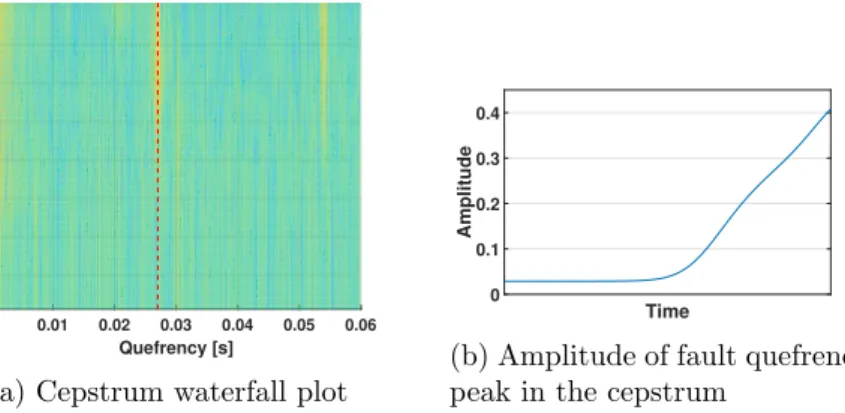
Lastly, Figs. 4a & 4b present results obtained from analyzing the signals with the cepstrum directly. Since the cepstrum essentially groups together harmonics in the spectrum into a smaller subset of peak, it is less effective at detecting bearing faults. These faults do not produce discrete harmonics initially due to the random slippage.
0.01 0.02 0.03 0.04 0.05 0.06 Quefrency [s] 10 20 30 40 50 60 70 80 Sample
(a) Cepstrum waterfall plot
Time 0 0.1 0.2 0.3 0.4 Amplitude
(b) Amplitude of fault quefrency peak in the cepstrum
Figure 4: Simulated results using cepstrum analysis
4. Results
This section demonstrates results obtained through the signal processing pipelines as proposed in Section 3, applied on real wind turbine vibration signals with confirmed drivetrain faults. These are summarised in Table 1.
Table 1: Faults analysed.
Fault Location Failure Mode Turbine Rating Fault Order
Planet Wheel Tooth Crack Offshore 2-4 (MW) 0.76
Planet Bearing Inner Race Offshore 2-4 (MW) 0.94
The faults examined are a planet wheel tooth crack (fault order around 0.76) and a planet
bearing inner race fault (fault order around 0.95) from two offshore wind turbines. Both
components were replaced on March 2018 and July 2018 respectively.
The challenge with real wind turbine vibration signals is that they are often sparsely collected. The frequency of collection depends on the operator but it can be weekly for older turbines or daily for newer installed turbines and condition monitoring systems. It should be kept in mind that the operational conditions of the turbine (e.g. speed, power level) affect the vibration signals, so similar power levels should be compared for diagnostic purposes. Also, sometimes data reduction is implemented, so data collected in past time periods might be deleted for storage reasons making it harder to analyse historic faults.
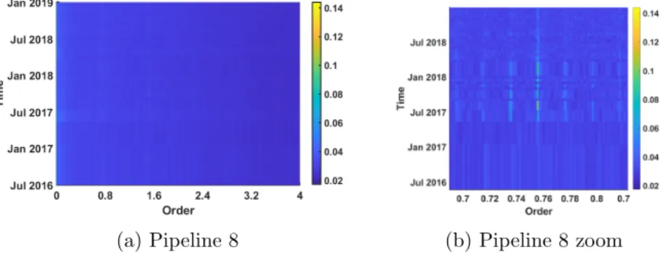
4.1. Planet Wheel Tooth Crack
Some indicative results of the planet wheel tooth crack are shown in Fig. 5. The figure shows pipeline 8, where it can be seen in the zoomed filterbank (Figure 5b) that from July 2017 there is an increase in the envelope amplitude, until March 2018 where the wheel was replaced.
(a) Pipeline 8 (b) Pipeline 8 zoom
Figure 5: Pipeline 8 results from planet wheel crack. From July 2017 there is an increase in the envelope amplitude, until March 2018 where the wheel was replaced.
4.2. Planet Bearing Inner race Fault
The pipeline results for the planet bearing fault are shown in this section. Some indicative results from pipeline 1 are depicted in Figure 6a, for above rated power levels. The kurtosis indicator is calculated for different filterbands. Each line shows a particular filterband. No indication of fault development is apparent prior to the fault. There seems to be a rapid increase in the kurtosis in the a few filterbands, but that happens after the bearing replacement, which can be justified due to change of stiffness in the mechanical components of the system.
Jul 2017 Oct 2017 Jan 2018 Apr 2018 Jul 2018 Oct 2018 Jan 2019
Time 0 20 40 60 80 Amplitude
(a) Pipeline 1 results from the kurtosis indicator for planet bearing fault
(b) Results from pipeline 6: angular resampling and au-topower spectrum tracking Figure 6: Pipelines 1 and 6 results
The results of pipeline 6 are shown in Figure 6b. Pipeline 6 tracks the autopower spectrum and the amplitude of the peak close to the fault order. This peak has a consistent value, with no clear change before the failure. Planet bearing faults can be hard to diagnose through frequency spectra, since their signatures can be masked by other components, as discussed in [26].
However, pipeline 7 (angular resampling and enveloping) seems to successfully detect the incipient planet bearing fault. Figure 7aa shows the evolution of the fault amplitude around
the fault order by means of a zoomed waterfall plot of the envelope spectra. There is a
significant increase around the fault order, from January 2018 until replacement in July 2018. The amplitude of the fault order peak is extracted and depicted in Fig. 7b where its increase with respect to the developing fault is even more clear, and it drops after replacement in July 2018. It is also discussed in past literature that envelope analysis is effective for diagnosing bearing faults [27].
Pipeline 8 shows some increase in the envelope amplitude, leading up to the bearing fault, but does not seem as reliable for this particular case as pipeline 7. This indicates that a multipronged
approach with regards to processing vibration data of wind turbine drivetrains is recommended. The performance of different methodologies can be highly variable with the fault case.
0.9500 0.9504 0.9508 0.9512 0.9516 Order Jul 2017 Oct 2017 Jan 2018 Apr 2018 Jul 2018 Oct 2018 Jan 2019 Time
(a) Results from pipeline 7
Jul 2017 Oct 2017 Jan 2018 Apr 2018 Jul 2018 Oct 2018 Jan 2019
Time 0.6 0.7 0.8 0.9 1 1.1 1.2 1.3 1.4 Feature Amplitude Above rated Below Rated
(b) Feature from pipeline 7 (c) Results from pipeline 8
Figure 7: Pipeline 7 and 8 results for the data containing a planet bearing inner race fault
5. Conclusions
This paper presents several multi-step processing pipelines for wind turbine drivetrains. The pipelines apply different advanced signal processing algorithms in parallel on the raw
time-domain waveforms. The proposed methodology is validated on operational wind turbine
vibration signals, with confirmed faults on the planet gear and planet bearing. It is shown that the performance of the different pipelines is often fault dependent. Therefore, the diversified parallel multi-step processing approach can increase robustness in the early detection rate of wind turbine drivetrain faults and subsequently the condition monitoring strategies and maintenance decision making of wind farm operators. Future work includes condition indicator selection and diagnostic practices.
References
[1] Estefania Artigao, Sergio Mart´ın-Mart´ınez, Andr´es Honrubia-Escribano, and Emilio G´
omez-L´azaro. Wind turbine reliability: A comprehensive review towards effective condition monitoring
development. Applied energy, 228:1569–1583, 2018.
[2] Fausto Pedro Garc´ıa M´arquez, Andrew Mark Tobias, Jes´us Mar´ıa Pinar P´erez, and Mayorkinos
Papaelias. Condition monitoring of wind turbines: Techniques and methods. Renewable Energy,
46:169–178, 2012.
[3] Shuangwen Sheng. Wind turbine gearbox condition monitoring round robin study-vibration analysis. Technical report, National Renewable Energy Lab.(NREL), Golden, CO (United States), 2012. [4] Eric Bechhoefer and Brent Butterworth. A comprehensive analysis of the performance of gear fault
detection algorithms. InProceedings of the Annual Conference of the PHM Society, volume 11, 2019.
[5] Sofia Koukoura, James Carroll, Alasdair McDonald, and Stephan Weiss. Comparison of wind turbine
gearbox vibration analysis algorithms based on feature extraction and classification. IET Renewable
Power Generation, 13:2549–2557, 2019.
[6] Wenxian Yang, Peter J Tavner, Christopher J Crabtree, Y Feng, and Y Qiu. Wind turbine condition
monitoring: technical and commercial challenges. Wind Energy, 17(5):673–693, 2014.
[7] Timothy Verstraeten, Ann Nowe, Jonathan Keller, Yi Guo, Shuangwen Sheng, and Jan Helsen.
Fleetwide data-enabled reliability improvement of wind turbines.Renewable and Sustainable Energy
Reviews, 109:428–437, 2019.
[8] KR Fyfe and EDS Munck. Analysis of computed order tracking. Mechanical Systems and Signal
Processing, 11(2):187–205, 1997.
[9] C´edric Peeters, Quentin Lecl`ere, J´erˆome Antoni, Peter Lindahl, John Donnal, Steven Leeb, and Jan
Helsen. Review and comparison of tacholess instantaneous speed estimation methods on experimental
[10] Shawki A Abouel-seoud. Fault detection enhancement in wind turbine planetary gearbox via
stationary vibration waveform data.Journal of Low Frequency Noise, Vibration and Active Control,
37(3):477–494, 2018.
[11] Tianyang Wang, Qinkai Han, Fulei Chu, and Zhipeng Feng. Vibration based condition monitoring
and fault diagnosis of wind turbine planetary gearbox: A review. Mechanical Systems and Signal
Processing, 126:662–685, 2019.
[12] Robert B Randall. A history of cepstrum analysis and its application to mechanical problems.
Mechanical Systems and Signal Processing, 97:3–19, 2017.
[13] Giorgio Dalpiaz, Alessandro Rivola, and Riccardo Rubini. Effectiveness and sensitivity of vibration
processing techniques for local fault detection in gears. Mechanical systems and signal processing,
14(3):387–412, 2000.
[14] C´edric Peeters, Patrick Guillaume, and Jan Helsen. Vibration-based bearing fault detection for
operations and maintenance cost reduction in wind energy. Renewable Energy, 116:74–87, 2018.
[15] J´erˆome Antoni. The spectral kurtosis: a useful tool for characterising non-stationary signals.
Mechanical systems and signal processing, 20(2):282–307, 2006.
[16] Jerome Antoni. Fast computation of the kurtogram for the detection of transient faults. Mechanical
Systems and Signal Processing, 21(1):108–124, 2007.
[17] Tianyang Wang, Fulei Chu, and Zhipeng Feng. Meshing frequency modulation (mfm) index-based
kurtogram for planet bearing fault detection. Journal of Sound and Vibration, 432:437–453, 2018.
[18] Tomasz Barszcz and Robert B Randall. Application of spectral kurtosis for detection of a tooth crack
in the planetary gear of a wind turbine.Mechanical Systems and Signal Processing, 23(4):1352–1365,
2009.
[19] Cedric Peeters, Patrick Guillaume, and Jan Helsen. A comparison of cepstral editing methods as
signal pre-processing techniques for vibration-based bearing fault detection.Mechanical Systems and
Signal Processing, 91:354–381, 2017.
[20] J Antoni and RB Randall. Unsupervised noise cancellation for vibration signals: part ii—a novel
frequency-domain algorithm. Mechanical Systems and Signal Processing, 18(1):103–117, 2004.
[21] J Antoni and RB Randall. Unsupervised noise cancellation for vibration signals: part i a novel
frequency domain algorithm. Mechanical Systems and Signal Processing, 18(1):103–117, 2004.
[22] Nader Sawalhi and Robert B Randall. The application of spectral kurtosis to bearing diagnostics. InProceedings of ACOUSTICS, pages 3–5, 2004.
[23] D Abboud, J Antoni, S Sieg-Zieba, and M Eltabach. Envelope analysis of rotating machine vibrations
in variable speed conditions: A comprehensive treatment.Mechanical Systems and Signal Processing,
84:200–226, 2017.
[24] JJA Moors. A quantile alternative for kurtosis. Journal of the Royal Statistical Society: Series D
(The Statistician), 37(1):25–32, 1988.
[25] C´edric Peeters, J´erˆome Antoni, and Jan Helsen. Blind filters based on envelope spectrum sparsity
indicators for bearing and gear vibration-based condition monitoring.Mechanical Systems and Signal
Processing, 138:106556, 2020.
[26] Sofia Koukoura, J Carroll, A McDonald, and S Weiss. Wind turbine gearbox planet bearing failure
prediction using vibration data. InJournal of Physics: Conference Series, volume 1104, page 012016.
IOP Publishing, 2018.
[27] Robert B Randall and J´erˆome Antoni. Rolling element bearing diagnostics—a tutorial. Mechanical