Rapid Progress of a Thermal Arrayed Waveguide
Grating Module for Dense Wavelength Division
Multiplexing Applications
Abd El–Naser A. Mohamed1, Ahmed Nabih Zaki Rashed2*, and Mahmoud M. A. Eid3 1,2,3Electronics and Electrical Communications Engineering Department
Faculty of Electronic Engineering, Menouf 32951, Menoufia University, EGYPT
2*
E-mail: [email protected]
---ABSTRACT---
In the present paper, we have proposed a thermal planar arrayed waveguide grating (AWG) module for dense wavelength division multiplexing (DWDM) which is composed of one of the following material as a core such as Pure silica glass (SiO2), Lithium niobate (LiNbO3), and gallium aluminum arsenide (Ga (1-x)Al(x)As)/Polyhexafluoro isopropyl 2-fluoroacrylate dibutyl phathalate (PHFIP 2-FA-DBP) used as over cladding material/Polyhexafluoro isopropyl 2-fluoroacrylate (PHFIP 2-FA) used as under cladding material, hybrid materials on a silicon substrate has parametrically investigated over wide range of the affecting parameters. multiplexing technique is processed where multi channels in ultra dense wavelength division multiplexing in a thermal AWG module. We have theoretically investigated the temperature dependent wavelength shift of the AWG depends on the refractive indices of the materials and the size of the waveguide. A thermalization of the AWG can be realized by selecting proper values of the material and structural parameters of the device. We have taken into account the increased number of transmitted channels within DWDM technique over a thermal planar AWG of hybrid materials. The thermal effects of different hybrid materials employed in the fabrication of AWG are studied deeply and parametrically for the good performance of such AWG.
Keywords- A thermal AWG, Planar waveguide, UW-DWDM, UW-SDM, PHFIP 2-FA, PHFIP 2-FA-DBP, Hybrid materials.
---
Date of Submission: July 03, 2011 Date of Acceptance: August 07, 2011 ---I. INTRODUCTIONT
he performance of wavelength division multiplexing (WDM) optical networks [1] greatly depends on the spectral characteristics of their components. One key component of WDM networks is the arrayed waveguide grating (AWG), which can serve as a wavelength router, multiplexer, and demultiplexer. In order to allow the concatenation of many such devices and reduce the need for accurate wavelength control, their filter response must approximate a rectangular function. Various techniques have been proposed in order to broaden and flatten the transfer function of an AWG. AWG is an extremelyversatile device that features and combines simultaneously unique periodic spatial and frequency properties and the possibility of integration on a chip [2]. The AWG has been proposed for the implementation of multiple applications that embrace the fields of devices, systems, and networks. Examples of these include the production of spectrum-sliced sources, dispersion compensation, wavelength division multiplexing multiplexers and demultiplexers, tunable filters, wavelength routing , and optical processing. The range of application is very extensive, and the specific design requirements may differ substantially in terms of insertion losses and their spectral uniformity, frequency periodicity, channel bandwidth, cyclic nature, polarization sensitivity, and crosstalk. AWG device
achieve a larger scale AWG, then to increase its port count. However, as the port count increases, the length of the slab waveguides tend to increase to make it possible to align all the input/output waveguide ports along them [5]. In the present study, a hybrid material waveguide with silica-doped as core material, Polyhexafluoro isopropyl 2-fluoroacrylate as overcladding material, Polyhexafluoro isopropyl 2-fluoroacrylate dibutyl phathalate as undercladding material are considered as the most attractive a thermal structure because of its resistance to the thermo-optic sensitivity of the materials treated over wide range of the affecting parameters. First, we have presented the principle of the a thermal planar arrayed waveguide grating with the following materials as a core waveguide such as pure silica glass (SiO2), Lithium
niobate (LiNbO3), and gallium aluminum arsenide (Ga (1-x)Al(x)As)/Polyhexafluoro isopropyl 2-fluoroacrylate
dibutyl phathalate (PHFIP 2-FA-DBP) used as over cladding material/Polyhexafluoro isopropyl 2-fluoroacrylate (PHFIP 2-FA) used as under cladding material, hybrid materials are described, and the relative formulas are derived for analyzing the temperature dependence of the a thermal AWG. As well as we have
planned the theoretical analysis of the DWDM application in a thermal planar AWG are taken into account over wide range of the affecting parameters. Finally, a conclusion is reached based on the analysis and general discussion.
II. A thermal Arrayed Waveguide Grating Module The index of refraction for the silica-doped glass from which the optical waveguides are made is temperature dependent, causing the center wavelength of the AWG to be temperature-dependent as well. Fig. 1 illustrates the principle of temperature dependence. Let us suppose that at room temperature (T0), the phase front of
the optical signals propagated in the arrayed waveguide forms an arc at the end of the slab waveguide, focusing the light at the center output waveguide. When temperature rises above room temperature, the effective index of refraction neff increases, resulting in an increase in the
arrayed waveguide phase difference (2π/λ) (∆L) neff,
where λ is the center wavelength and ∆Lis the difference in signal wavelength between adjacent arrayed waveguides.
Fig. 1. Principle of AWG module temperature dependence.
When the phase difference in the arrayed waveguide increases, the phase front becomes tilts, as can be seen in Fig. 1, and since light has the property of advancing perpendicular to the phase front, its focus point will shift.
That is to say light of differing wavelength will be output from the center output waveguide, and a wavelength shift will occur [6, 7].
III. Modeling Description and Analysis
As shown in Fig. 2, the thermal AWG with cross sections is designed as square shape with the core width a, of silica-doped as core material, Polyhexafluoro isopropyl
2-fluoroacrylate dibutyl phathalate and Polyhexafluoro isopropyl 2-fluoroacrylate as undercladding and overcladding materials respectively on a silicon substrate.
III. 1. Refractive index of hybrid materials III. 1. 1. Pure silica glass core material
The refractive-index of pure silica glass material waveguide based on empirical equation is given by [8]:
2 6 2 2 5 2 4 2 2 3 2 2 2 2 1 2 1 1 A A A A A A n − + − + − + = λ λ λ λ λ λ (1)
The empirical coefficients of the refractive index of this waveguide is cast as [8]: A1= 0.691663, A2=a2T;
a2=(0.0684043/T0), A3= 0.4079426, A4=a4T; a4 =
(0.1162414/T0), A5= 0.8974794, and A6=a6T; a6 =
(9.896161/T0).Where T is the ambient temperature in ºC, T0
is considered to be as room temperature. Differentiation the empirical equation with respect to operating wavelength λ
and ambient temperature [2, 7].
III. 1. 2. Lithium niobate core material
The refractive index of this waveguide is cast under the empirical equation is given by [7]:
2 10 2 9 2 8 7 2 6 5 2 4 3 2 1 2 1 ) ( λ λ
λ B B
M B B M B B M B B M B B n − − + + + − + + + = (2)
The set of parameters is dimensionally adjusted as [9]: B1=5.35583, B2=4.62x10⁻⁷, B3=0.100473, B4=3.862x10⁻⁸,
B5=0.20692, B6=-0.89x10⁻⁸, B7=100, B8=2.657x10⁻⁵,
B9=11.34927, B10=0.015334, and M= (T-T0)(T+570.82).
The simplified equation as given in [7]. As well as differentiations of empirical equation w. r. t operating wavelength λ, and ambient temperature T [2, 7].
III. 1. 3. Gallium aluminum arsenidecore material The parameters to characterize the temperature and operating wavelength dependence of the refractive-index from Sellmeier equation is given as by [10].
2 4 3 2 2 1 2
1 λ Cλ
C C C n − − + = (3)
The parameters is adjusted as [10]: C1= 10.906-2.92x,
C2=0.97501,C3=c3T2;c3=(0.52886-0.735x/T0)2,for x<0.36,
and C4=c4(0.93721+2.085710-4T); c4=0.002467(1.14x+1).
Differentiation of empirical equation w. r. t operating wavelength λ and ambient temperature T [10].
III. 1. 4. PHFIP 2-FA-DBP overcladding material The refractive-index of PHFOP 2-FA-DBP material waveguide based on empirical equation is given by [11]:
, 1 2 6 2 2 5 2 4 2 2 3 2 2 2 2 1 2 2 D D D D D D n − + − + − + = λ λ λ λ λ
λ (4)
The set of parameters of empirical equation coefficients of PHFIP 2-FA-DBP material waveguide as a function of ambient temperature and optical wavelength are cast as [11]: D1=0.2680, D2= 0.07913 (T/T0), D3= 0.3513, D4= 0.08381
(T/T0), D5= 0.2498, and D6= 0.1062 (T/T0). Then the
differentiation of Eq. (4) with respect to operating wavelength λ which yields:
(
) (
) (
)
, . 2 2 6 2 2 6 5 2 2 4 2 2 4 3 2 2 2 2 2 2 1 2 2 − + − + − − = D D D D D D D D D n d dn λ λ λ λλ (5)
III. 1. 5. PHFIP 2-FA undercladding material The refractive-index of PHFOP 2-FA material waveguide based on Sellemier equation is given by [11]:
, 1 2 6 2 2 5 2 4 2 2 3 2 2 2 2 1 2 3 E E E E E E n − + − + − + = λ λ λ λ λ
λ (6)
The set of parameters of Sellmeier equation coefficients of PHFIP 2-FA material waveguide as a function of ambient temperature, and wavelength are cast as [11]: E1=0.4200,
E2= 0.05874 (T/T0), E3= 0.0461, E4= 0.08755 (T/T0), E5=
0.3484, and E6= 0.09271 (T/T0). Then the differentiation of
Eq. (6) w. r. t λ which yields:
(
) (
) (
)
, . 2 2 6 2 2 6 5 2 2 4 2 2 4 3 2 2 2 2 2 2 1 3 3 − + − + − − = E E E E E E E E E n d dn λ λ λ λλ (7)
III. 2. A thermal AWG equations analysis
We have presented a thermal condition formulas of
silica-doped/PHFIP 2-FA-DBP/PHFIP 2-FA hybrid materials AWG on a silicon substrate. The temperature dependence of AWG center wavelength is expressed as [12].
+
= c c sub
c c c n dT dn n dT d α λ λ (8)
Where λc is the center wavelength of AWG in µm, nc is the
effective refractive-index of the arrayed waveguide grating,
αsub is the coefficient of thermal expansion of the Si
substrate, and dT
dnc is the thermo-optic (TO) coefficient of the waveguide. By integrating w. r. t temperature then Eq. (8), can be expressed as follows [13]:
( subT)
c c Cn eα
λ = (9)
Where C is an integrating constant. Assume that λc=λ0, and
nc=nc0 when T=T0 at room temperature, we can determine C
as the following expression:
( subTo)
co o e
n
C = λ −α (10)
Where nc0 is the effective refractive index at room
temperature. By substituting from Eq. (10) into Eq. (9), we can obtain the following expression:
[ sub(T To)] co c o c e n n − =λ α
λ (11)
Then from Eq. (12), the central wavelength shift caused by the temperature variation can be expressed as follows:
( )
( )
[
o co]
T T sub c co o o
c n e n
n −
= −
=λ λ λ α −
δλ (12)
Taking δλ = 0, from Eq. (12), the thermal condition of the AWG can be expressed as follows:
( ) = − c co o sub n n T T ln
α (13)
Differentiating Eq. (13) w. r. t temperature, a thermal condition of the AWG expressed in another form as [14]:
c sub nc
dT dn
α
−
= (14)
The effective refractive index of the hybrid materials for arrayed waveguide grating (AWG) is given by [15, 16]:
(
)
(
)
2 ,2 2 3 2 2 2 1 2 2 2 3 2 2 2 1 n b n n n k n b n n n k k
nc = − − +
+ − − =
=β (15)
Where β is the propagation constant of the fundamental mode, k is the wave number, and b is the normalized propagation constant and is given by [15]:
( )
1.1428 0.9660 , 2 − = V Vb (16)
Where V is the normalized frequency. For single mode step index optical fiber waveguide, the cut-off normalized is approximately V= Vc= 2.405, and by substituting in Eq.
(16), we can get the normalized propagation constant b at the cut-off normalized frequency approximately b ≈ 0.5, and then by substituting in Eq. (15) we can obtain:
The effective refractive index nc is dependent on the
refractive indices of the materials, then by selecting proper materials of the waveguide to satisfy Eq. (17), an a thermal AWG can be designed. Differentiation of Eq. (17) with respect to operating wavelength λ which yields:
, 2 1 3 3 2 2 1
1
+ − = λ λ λ λ d dn n d dn n d dn n n d dn c
c (18)
III. 3. Design parameters of a thermal AWG
The diffraction order m is an important parameter. Once the diffraction order m is determined, some other parameters of the a thermal AWG device are also determined, such as the length difference of adjacent waveguides, focal length of the slab waveguide, free spectral range, number of input/output wavelength channels, and number of the arrayed waveguides. In the following analysis, we have investigated the relations between the diffraction order m and the above parameters, and we are going to estimate its values. The path length difference between adjacent arrayed waveguides ∆L is:
, 0
c
n m L= λ
∆ (19)
Where m is the diffraction order, nc is the effective
refractive-index of a thermal AWG, and λ0 is the center
wavelength of the arrayed waveguide in µm. The focal length of slab waveguide is given by the equation [17]:
, 2 2 g c f n m n d L λ ∆
= (20)
Where d is the pitch length of adjacent input/output channels and arrayed waveguides in µm, ∆λ is the wavelength channel spacing in nm, and ng is the group refractive index
and is given as the following:
, 0 λ λ d dn n
ng= c− c (21)
An important property of the AWG is the free spectral range, also known as the demultiplexer periodicity. This periodicity is due to the fact that constructive interface at the output FSR can occur for a number of wavelengths. The free spectral range denotes the wavelength and frequency spacing between the maximum of the interface pattern because of the periodic characteristic of the AWG transfer function, and can be expressed as:
, 0 g c n m n
FSR=λ (22)
The maximum number of Input/Output wavelength channels Nmax depends on the FSR. The bandwidth of the multiplexed
light, that is Nmax∆λ must be narrow than an FSR to prevent
the overlapping of orders in the spectral region. Therefore, Nmax can be derived as [17]:
, int 0 max = eger FSRλ
N (23)
The number of the arrayed waveguides P is not a dominant parameter in the AWG design because the wavelength channel spacing ∆λ and maximum number of wavelength channels Nmax do not depend on it. Generally, P is selected so that the number of the arrayed waveguides is sufficient to make the numerical aperture, in which they form a greater number than the input/output waveguides, such that almost all the light diffracted into the free space region is collected by the array aperture. As a general rule, this number should be bigger than four times the number of channels [17]:
. 4Nmax
P= (24)
IV. Simulation Results and Performance Analysis We have proposed the operating center wavelength at room temperature T0=25 ºC is selected to be λ0= 1.55 µm,
which is one of the standard wavelengths recommended by the International Telecommunication Union (ITU) [16]. This AWG device is made on the silicon substrate have a coefficient of thermal expansion of αsub=2.63x10⁻⁶/ºC [16].
Because the environmental temperature of a thermal planar arrayed waveguide grating is usually changed from 25 ºC to 65 ºC and based on AWG multiplexing application to increases number of transmitted channels and then to increase number of subscribers within a thermal planar arrayed waveguide grating of hybrid materials. Based on the modeling equations analysis and the assumed set of the operating parameters as shown in Table 1.
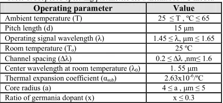
Table 1: Proposed operating parameters for a thermal AWG model. Operating parameter Value Ambient temperature (T) 25 ≤ T , ºC ≤ 65
Pitch length (d) 15 µm
Operating signal wavelength (λ) 1.45 ≤λ, µm ≤ 1.65
Room temperature (To) 25 ºC
Channel spacing (∆λ) 0.2 ≤∆λ ,nm≤ 1.6 Center wavelength at room temperature (λ0) 1. 55 µm
Thermal expansion coefficient (αsub) 2.63x10⁻⁶/ºC
Core radius (a) 4 ≤ a , µm ≤ 5 Ratio of germania dopant (x) x ≤ 0.3
The following facts and concepts are assured as shown in the series of the shown Figs. (3-14):
IV. 1. Variation of the refractive index of the core, n1.
Variations of n1 are investigated against variations of
the operating wavelength λ are displayed in Figs. (3-6) for all materials based a thermal AWG in our research as a core material. These figures clarify the following results:
i. As operating wavelength λ increases, this results in refractive index of core n1 for all materials used. In case
of using SiO2 as a core, there is slightly decreasing with
increasing the operating wavelength, but in case of using LiNbO3 or Ga(1-x)AlxAs, there is a significant
decreasing with increasing the operating wavelength. ii. As ambient temperature T increases, this leads to
refractive index n1 increases also for all materials which
used as core. For certain values of operating wavelength λ and ambient temperature T, value of refractive index n1 for Ga(1-x)AlxAs is the largest than
other materials based a thermal AWG.
IV. 2. Variation of theeffective refractive-index of the arrayed waveguide grating, nc.
Variations of nc are investigated against variations of
the operating wavelength are displayed in Figs. (7-10) for all materials used in our research as a core material. These figures clarify the following results:
i. As operating wavelength λ increases, this leads to effective refractive index nc decreases for all materials
used. In the case of using SiO2 as a core, there is
slightly decreasing with increasing the operating wavelength, but in case of using LiNbO3 or Ga(1-x)AlxAs
ii. As operating wavelength λ increases, this leads to effective refractive index nc decreases for all materials
used. In the case of using SiO2 as a core, there is
slightly decreasing with increasing the operating wavelength, but in case of using LiNbO3 or Ga(1-x)AlxAs
there is a significant decreasing with increasing the operating wavelength.
iii. As T increases, nc increase also for all material which
used as a core. For certain value of operating wavelength λ and ambient temperature T, value of
effective refractive index nc for Ga(1-x)AlxAs is the
largest than other materials based a thermal AWG. IV. 3. Variation of dnc/dT.
Variations of dnc/dT are investigated against variations
of the temperature are displayed in Figs. (11-14) for all materials. These figures clarify the following:
i. For all materials used in our research as a core as ambient temperature T increases, dnc/dT decreases.
ii. For all materials used in our research as a core at a certain value of ambient temperature as operating wavelength λ increases, dnc/dT also increases.
V. Conclusions
In a summary, we have investigated a thermal AWG for DWDM applications. It is observed that variations of rate of change of effective refractive-index with respect to ambient temperature at a certain operating wavelength in the case of a thermal AWG is lower than the case of conventional AWG devices, which emphasis a thermalization concept with coating with polymeric materials for reducing temperature effects as overcladding and undercladding materials. As well as we have tested and investigated three different as core materials for a thermal AWG such as SiO2, LiNbO3, and Ga(1-x)AlxAs. It is
indicated pure silica glass presents the lowest rate of change of effective refractive index against rate of change of temperature than other materials based a thermal AWG when coating with polymeric materials. Moreover we have
demonstrated that the increasing diffraction order, the decreased free spectral range, focal length of slab waveguide, number of input/output wavelength channels, and number of arrayed waveguides. Also the increased ambient temperature, the decreased number of transmitted channels, and number of arrayed waveguides. It is evident that pure silica glass (SiO2) has presented the highest
number of transmitted I/O wavelength channels, and number of arrayed waveguides than the other core materials based a thermal AWG under the same operating parameters and conditions. As well as we have compared the operating design parameters for conventional and a thermal AWG are summarized in the following Table 2 under the same conditions of operating parameters.
Table 2: Best operating parameters of materials based conventional and a thermal AWG for multiplexing/demultiplexing applications in multi band regions.
Materials based Conventional AWG Materials based A Thermal AWG
Same conditions of operation
1.45 µm ≤ Operating wavelength, λ ≤ 1.65 µm, Room temperature (T0)=25 ºC, Center wavelength (λ0) = 1.55 µm, Channel spacing, ∆λ= 0.2 nm.
Operating parameter Diffraction order, m = 15.5
Materials based AWG Pure silica LiNbO3 Ga(1-x)Al(x)As Pure silica LiNbO3 Ga(1-x)Al(x)As
Free spectral range (FSR), mm
98.73 97.96 95.84 98.72 97.96 95.85
Number of I/O wavelength channels, Nmax
494 490 479 494 490 479
Number of arrayed waveguides, P
1976 1960 1916 1976 1960 1916
Rate of change of the refractive index with
temperature, dn/dT , °C-1 7.43 x 10⁻⁴ 3.75 x 10⁻⁵ 3.4 x 10⁻⁴ -2.72 x 10⁻⁶ -4 x 10⁻⁶ -6.11 x 10⁻⁶
It is indicated from our comparison that conventional and a thermal AWG presents nearly the same values of free spectral range, number of I/O wavelength channels, and number of arrayed waveguides. But in the case of rate of
change of refractive index with temperature for a thermal AWG is lower than conventional AWG that permits low dispersion, losses and high bit rates within a thermal than conventional AWG devices.
REFERENCES
[1] Abd El-Naser A. Mohammed, Abd El-Fattah A. Saad, and Ahmed Nabih Zaki Rashed and Mahomud M. Eid, Characteristics of Multi-Pumped Raman Amplifiers in Dense Wavelength Division Multiplexing (DWDM) Optical Access Networks IJCSNS International Journal of Computer Science and Network Security, 9(2), 2009 277-284.
[2] Abd El-Naser A. Mohammed, Abd El-Fattah A. Saad, and Ahmed Nabih Zaki Rashed, Applications of Arrayed Waveguide Grating (AWG) in Passive Optical Networks, IJFGCN International Journal of Future Generation Communication and Networking, 2(2),
2009, 25-36.
Gratings For the Visible Wavelength Range NTT Techanical Review, 4(6), 2006, 48-51.
[4] M. L. Calvo, P. Cheben, S. Janz, J. A. Rodrigo, D-X. Xu, and A. Delage, Arrayed Waveguide Grating Based on Group Index Modification, J. of Lightwave Technol., 24(3), 2006, 1551-1559.
[5] A. Bernussi, V. Gorbounor, and H. Temakin, Temperature Insensitive Refractive Arrayed Waveguide Grating Multiplexers, IEEE Photonics Technol. Letters, 16(3), 2004, 831-833.
[6] E-S. Kang, W-S. Kim, D-J. Kim, and B-S. Bae, Reducing the Thermal Dependence of Silica-Based Arrayed Waveguide Grating Using Inorganic-Organic Hybrid Materials, IEEE Photonics Technol. Letters, 16(12), 2004, 2625-2627.
[7] Abd El-Naser A. Mohammed, Gaber M. El-Abyad, Abd El-Fattah A. Saad, and Ahmed Nabih Zaki Rashed, High Transmission Bit Rate of A thermal Arrayed Waveguide Grating (AWG) Module in Passive Optical Networks, IJCSIS International Journal of Computer Science and Information Security, 1(1), 2009, 13-22.
[8] ITU-T, series G, General aspects of optical fiber cable, pp. 10-11, 2009.
[9] D. H. Jundt, Temperature-dependent Sellmeier equation for the index of refraction, ne, in congruent lithium
niobate, Optics Letters, 22(20), 1997, 1553-1555.
[10] Osama A. Oraby, Propagation of An Electromagnetic Beams in Nonlinear Dielectric Slab Wave Guides,
Minufiya Journal of Electronic Engineering Research, 16(1), 2006, 27-44.
[11] T. Ishigure, E. Nihei, and Y. Koike, Optimum Refractive Index Profile of The Grade-Index Polymer Optical Fiber, Toward Gigabit Data Link, Appl. Opt., 35(12), 1996, 2048-2053.
[12] C. S. Ma, Z. K. Qin, and H. M. Zhang, Design of A thermal Arrayed Waveguide Grating (AWG) Using Silica/Polymer Hybrid Materials, Optica Applicata Journal, XXXVII(3), 2007, 305-312.
[13] S. Yoneda, and S. Matsuura, Temperature-Independent Optical Filter at 1.55 µm Wavelength Using A silica-Based A thermal Waveguide, Electron. Lett., 34(4),
2003, 367–369.
[14] A. Kaneko, S. Kamei, Y. Inoue, and H. Takahashi, A thermal Silica-Based arrayed Waveguide Grating (AWG) Multi/Demultiplexer With New Low Loss Groove Design, Electronics Letters, 23(4), 2004, 3-5. [15] Abd Naser A. Mohammed, Gaber E. S. M.
El-Abyad, Abd El-Fattah A. Saad, and Ahmed Nabih Zaki Rashed, Low Loss A thermal Arrayed Waveguide Grating (AWG) Module for Passive and Active Optical Network Applications, International Journal of Communication Networks and Information Security (IJCNIS), 1(2), 2009, 27-34.
[16] Abd Naser A. Mohammed, Gaber E. S. M. El-Abyad, Abd El-Fattah A. Saad, and Ahmed Nabih Zaki Rashed, Ultra Low Loss A thermal Arrayed Waveguide Grating (AWG) Module for High Data Transmission Bit rate, International Journal of Photonics, 2(1), 2010,
31-40.
[17] Abd El-Naser A. Mohammed, Abd El-Fattah A. Saad, and Ahmed Nabih Zaki Rashed, Estimated Optimization Parameters of Arrayed Waveguide
Grating (AWG) for C-Band Applications, International Journal of Physical Sciences, 4(4), 2009, 149-155.
Biographies and Photographs