IJSRSET1284212 | Received : 05 May 2018 | Accepted : 17 May 2018 | May-June-2018 [(4) 8 : 257-264 ]
257
ANFIS Back-EMF Observer for Improving Performance of
Sensorless Brushless DC Motor Drive
Challa Swathi1, G. V. Marutheswar2
1PG Student, Department of EEE, S V University College of Engineering, Tirupati, Andhra Pradesh, India
2Professor, Department of EEE, S V University College of Engineering, Tirupati, Andhra Pradesh, India
ABSTRACT
In this paper, a novel sensorless brushless DC (BLDC) engine drive utilizing the ANFIS back-EMF spectator is proposed to enhance the execution of customary sensorless drive strategies. Most existing sensorless techniques for the BLDC engine have low execution at homeless people or low speed extend and every so often require extra circuit. To adapt to this issue, the estimation of a back-EMF utilizing the fuzzy rationale is appropriate for superior on the grounds that the back-EMF of the BLDC engine has a trapezoidal shape. The proposed calculation utilizing ANFIS back-EMF eyewitness can accomplish hearty control for the difference in an outer condition and persistently appraise speed of the rotor at homeless people and also consistent state. The power of the proposed calculation is demonstrated through the reproduction and is contrasted with different sensorless drive techniques.
I.
INTRODUCTIONThe brushless DC (BLDC) engine has been utilized as a part of numerous applications, for example, apparatus, PC, programmed office machine, robots for mechanization of manufactory, drives of numerous hardware and minuteness machine. The BLDC engine has favorable circumstances of the DC engine, for example, basic control, high torque, high effectiveness and smallness. Likewise, brush upkeep is never again required, and numerous issues coming about because of mechanical wear of brushes and commutators are enhanced by changing the situation of rotor and stator in DC engine. To interchange the capacity of brushes and commutators, the BLDC engine requires an inverter and a position sensor that recognizes rotor position for legitimate replacement of current [1]. In any case, the issues for the cost and unwavering quality of rotor position sensors have roused inquire about in the territory of position sensorless BLDC engine drives. As of late, numerous
sensorless drive strategies have been proposed for enhancing the execution of BLDC engines without a position sensor [2]-[5]. In any case, generally existing sensorless drive techniques for the BLDC engine have low execution in transient state or low speed run and at times require extra circuits.
II.
BLDC MOTOR DRIVE SYSTEMFor the most part, the BLDC engine drive framework can be demonstrated as an electrical comparable circuit that comprises of a protection, an inductance and back-EMF per a stage. The electrical comparable circuit and drive execution of this framework is appeared in Figure 1.
(a)
(b)
Figure 1. General performance of BLDC motor system. (a) The electrical equivalent circuit. (b) Waveforms of
back EMF, phase current, and developing torque.
Assuming that self and mutual inductances are constant, the voltage equation of three phases is given by
[ ]=[ ]+ [ ]
[ ]+ [ ]
(1)
The torque equation is given by
(2)
Where va, vb, and vc are phase voltages. Ra, Rb, and Rc are phase resistances. ia, ib, and ic are phase currents. La, Lb, and Lc are phase inductances. ea, eb, and ecare phase back–EMFs. is rotor speed.
III.
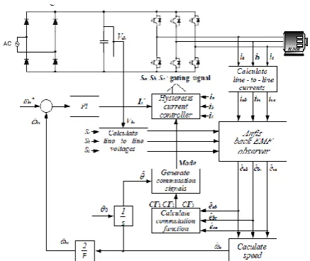
PROPOSED SENSORLESS CONTROL METHODA.The Proposed Sensorless Control Algorithm The overall structure of the proposed sensorless drive system is given in Figure 2.
Figure 2. The overall structure of the proposed fault tolerant drive system.
The hysteresis current controller is utilized for each stage current control. The line-to-line voltage is computed in light of the DC-connect voltage and exchanging status of the inverter. In a run of the mill sensorless drive arrangement of the BLDC engine, the constrained arrangement of the rotor is the way setting an underlying position. This strategy is additionally utilized as a part of the proposed sensorless drive calculation. The fuzzy back-EMF eyewitness gives an expected estimation of the back-EMF. The speed, the rotor position and the replacement work are computed by the evaluated back-EMF. The replacement flag age piece creates recompense signals in light of computed estimations of the position what's more, the substitution work.
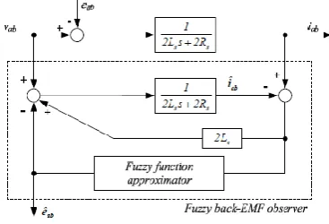
B. Fuzzy Back-EMF Observer
the proposed fuzzy back-EMF ob server is appeared in Figure 3.
Figure 3. Block diagram of Fuzzy back-EMF observer.
Since the neutral point of the BLDC motor is unknown when manufactured, this observer is considered by the following line-to-line equation:
=
(3)
The equation (6), (7) is represented by system state equation.
(4)
(5)
Where
A= [
] , B=[ ], F=[ ], C=[ ], x=[ ], y=[ ],
u=[ ], w=[ ]
Back-EMF is viewed as aggravation in (4). This unsettling influence is hard to assume.
For the most part, an unsettling influence model can speak to most unsettling influence models by expanding the level of polynomial differential condition. Notwithstanding, this aggravation model cannot precisely speak to the back-EMF of trapezoidal shape, so a fuzzy capacity approximate that can gauge willful non-direct work is connected to the back-EMF aggravation display in this paper. The contributions of the fuzzy capacity approximate are the line-to-line current mistake of the BLDC engine and the
differential value of the mistake. These sources of info are given by
( ) ̂ (6)
( ) ( )( ) ( ) (7)
The fuzzy capacity guess incorporates three phases: fuzzification, induction component and defuzzification.
1) Fuzzification:
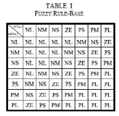
Fuzzification licenses to change over contributions to fuzzy factors by utilizing enrollment capacities. Each information and yield has seven sets related with seven phonetic marks: Negative Large (NL), Negative Medium (NM), Negative Small (NS), Zero (ZE), Positive Small (PS), Positive Medium (PM), Positive Large (PL) (Figure 4). All sets are defined on the defuzzified output is given by same discourse universe [-1,1].
Figure 4. Membership function.
2) Inference mechanism:
In this step, the value of the fuzzy output is determined using a rule base. A typical rule is described as:
IF (condition 1) AND (condition 2) THEN (conclusion)
method which has been chosen is the Max-Min method [7] which was proposed by Mamdani.
( ) ( ) ( ̂ )
( ) ( ) ( ̂ )
(8)
( ) ( ) ( ̂ )
Table I shows the rule-base. The database contains descriptions of the input and output variables.
3) Defuzzification:
The output of the inference mechanism is fuzzy output variable. The fuzzy function approximate must convert its internal fuzzy output variables into crisp values that the actual system can use these variables. One of the most common ways is the Center of Area (COA) method [7]. The defuzzified output is given by
̂
∑ ( )
∑ ( )
(9)
If the defuzzified output at time k is ̂ ( ) , the
overall crisp output of the observer will be
̂ ( ) ̂ ( ) ̂ ( ) (10)
C. Commutation Function
In this paper, the commutation function is defined by the estimated back-EMF using the proposed fuzzy back-EMF observer. Figure 5 shows the commutation function.
Figure 5. Commutation function.
Although similar commutation function was already proposed [8], the proposed commutation function in this paper is easy to decide the threshold of commutation function because it has a negative value before commutation. Also, since this commutation function is consisted of the estimated back-EMF, it is robust for noise.
The commutation functions are as follows: Model 1 and 4: CF ( ) =
(11) Model 2 and 5: CF ( ) =
(12) Model 3 and 6: CF ( ) =
(13)
D. The Estimation of Speed and Position
There is following relation between the dimension and speed of back-EMF in BLDC motor.
(14)
Where E is back-EMF dimension, Ke is back-EMF constant, and ωe is electrical angular velocity.
The speed can be also estimated by using back-EMF that the state observer offers as follows:
̂ ̂ (15)
̂ ̂ (16)
The rotor position is obtained by integrating speed. ̂ ∫ ̂ (17)
Where is initial position of rotor
IV.
EXTENSION TOPICAdaptive neuro-fuzzy controller
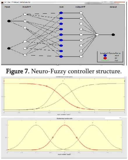
A fuzzy inference system and a back propagation algorithm. For an ordinary fuzzy inference, the parameters in the membership functions are usually determined by experience or the trial-and-error method. However, the adaptive neuro-fuzzy inference system can overcome this disadvantage through the process of learning to tailor the membership functions to the input/output data in order to account for these types of variations in the data values, rather than arbitrarily choosing parameters associated with a given membership function. This learning method works similarly to that of neural networks.
Adaptive Neural Fuzzy Inference System (ANFIS) is fuzzy Sugeno model put in the framework to facilitate learning and adaptation procedure. Such network makes fuzzy logic more systematic and less relying on expert knowledge. The objective of ANFIS is to adjust the parameters of a fuzzy system by applying a learning procedure using input–output training data. Basic architecture of ANFIS that has two inputs x and y and one output f.
In matlab the main difference between fuzzy controller and adaptive neuro fuzzy controller is only we have in matlab two types fuzzy controllers one is mamdani and second one is Sugeno.
Mamdani is ordinary fuzzy controller in this we provide input and output by using some assumptions but in Sugeno type we provide inputs only they automatically train outputs this is the main difference between two fuzzy controllers in matlab.
So mamdani type fuzzy controller used as ordinary fuzzy controller and Sugeno type fuzzy controller used as adaptive neuro fuzzy controller in matlab.
Figure 6. Block diagram of ANFIS estimator.
Figure 7. Neuro-Fuzzy controller structure.
Figure 8. Membership function.
Table 2. Rule Base
e/ n z p
n p p Z
z p z n
p z n n
V.
SIMULATION RESULTS
Table 3. Ratings and Parameters of BLDC Motor Rated Voltage V 160 (V)
Rated Torque Te 0.662 (Nm) Rated Speed Nr 3500 (rpm) Resistance Rs 0.75 (Ω) Inductance Ls 0.0031 (H)
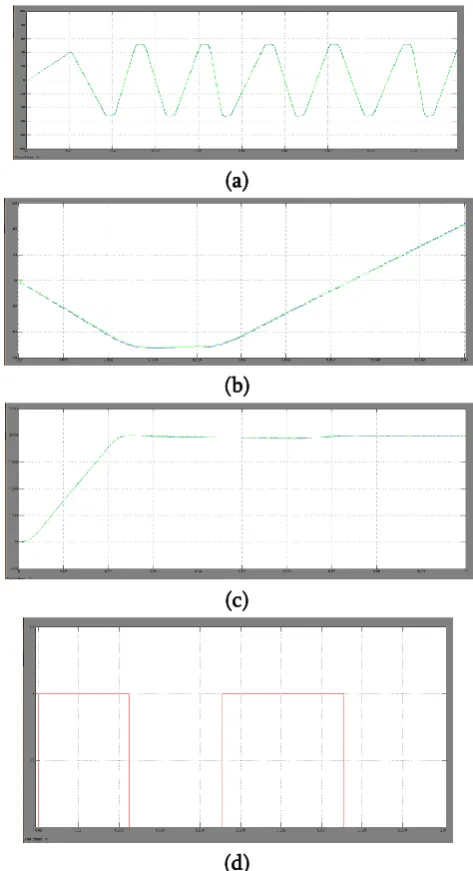
Figure 9 is the results of the back-EMF disturbance model using the first order differential equation. An estimation of constant back-EMF shows satisfied results as Figure 9(a), (b). But in the case of the back-EMF changes, the estimated value shows a delay. As a result, transient state of the rotor speed and a commutation signal has a delay as in Figure 9(c), (d). Figure 10 is the results of the back-EMF disturbance model using the second order differential equation. Contrary to the first order differential model, an estimation of a changing back-EMF shows good performance. But in the case of constant back-EMF shows good estimation results as in Figure 10(a), (b). As a result, the rotor speed on steady state has ripple as Figure 10(c). But a commutation signal is high performance because an estimation of changed back-EMF is superior as Figure 10(d).
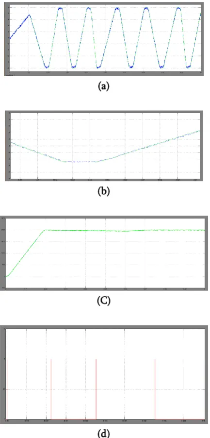
Figure 11 is the results of the fuzzy-back EMF observer to solve problems of the polynomial differential disturbance model. Because fuzzy logic can estimate a variable shape function as back-EMF of the BLDC motor, both constant and varying EMF are excellently estimated by the fuzzy back-EMF observer as Figure 11(a), (b). As a result, the performance of both the rotor speed on entire states and the commutation signal is much superior compared with observers using the back-EMF disturbance model consisted of polynomial differential equations.
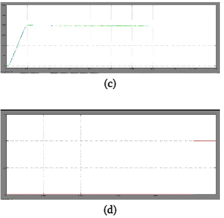
Figure 12 is the results of the proposed ANFIS back-EMF observer to solve the problems of of polynomial differential disturbance model and fuzzy controller disturbance model.ANFIS back-EMF observer can excellently estimate both constant and varying
back-EMF as shown in Figure 12(a), (b).Rotor speed is much superior compared with fuzzy controller disturbance model and commutation signal has high performance compared with observers using the back-EMF disturbance model consisted of polynomial differential equations.
(a)
(b)
(c)
(d)
Figure 9. Simulation results of the observer using first order disturbance model
(a)
(b)
(C)
(d)
Figure 10. Simulation results of the observer using second order disturbance model.
(a) Back-EMF. (b) Extended Line-to-line back-EMF. (c) Rotor speed. (d) Commutation signal.
(a)
(b)
(c)
(d)
Figure 11. Simulation results of the Fuzzy back-EMF observer. (a) Back-EMF. (b)Extended Line-to-line back-EMF. (c) Rotor speed. (d) Commutation signal.
(a)
(c)
(d)
Figure 12. Simulation results of the proposed ANFIS back-EMF observer. (a) Back-EMF. (b) Extended
Line-to-line back-EMF. (c) Rotor speed (d)commutation signal.
VI.
CONCLUSION
Regular sensorless techniques for the BLDC engine have low execution in transient state or low speed run and sporadically require extra circuit.
To adapt to this issue, this paper proposed a ANFIS back-EMF eyewitness utilizing the substitution work by shut circle ceaselessly evaluates a back-EMF of trapezoidal shape. Additionally, the proposed calculation utilizing this ANFIS back-EMF onlooker can accomplish strong control for the difference in an outer condition and consistently evaluate a speed of the rotor at homeless people and additionally unfaltering state.
Therefore, the proposed sensorless drive technique without extra circuit has higher execution than customary sensorless strategies. Likewise, this proposed sensorless strategy can be effectively connected to industry applications requiring ease and dependable style drive of BLDC engine. The specialized legitimacy of the proposed calculation has
been appeared on the other side PC recreation utilizing the Matlab.
VII.
REFERENCES[1].T. J. E Miller, "Brushless Permanent-Magnet and Reluctance Motor Drives," Clarendon Press, Oxford 1989.
[2].S. Ogasawara and H. Akagi, "An Approach to Position Sensorless Drive for Brushless DC Motors," IEEE Trans. Ind. Appl., vol. 27, no. 5, pp. 928-933, Sep./Oct. 1991.
[3].J. C. Moreira, "Indirect Sensing for Rotor Flux Position of Permanent Magnet AC Motors Operating Over a Wide Speed Range," IEEE Trans. Ind. Appl., vol. 32, no. 6, pp. 1392-1401, Nov./Dec. 1996.
[4].H. R. Andersen and J. K. Pedersen, "Sensorless ELBERFELD Control of Brushless DC Motors for Energy-Optimized Variable-Speed Household Refrigerators," EPE Conf. Rec., vol. 1, pp. 314-318, Sep. 1997.
[5].Hyeong-Gee Yee, Chang-Seok Hong, Ji-Yoon Yoo, Hyeon-Gil Jang, Yeong-Don Bae and Yoon-Seo Park, "Sensorless Drive for Interior Permanent Magnet Brushless DC Motors," Electric Machines and Drives Conf. Record, 1997, IEEE International 18-21 pp. TD1/3.1-TD1/3.3, May 1997.
[6].Lefteri H. Tsoukalas and Robert E. Uhrig, "Fuzzy and Neural Approaches in Enginerring," John Wiley & Sons, Inc., 1997.
[7].C. C. Lee, "Fuzzy Logic in Control Systems: Fuzzy Logic Controller-Part Ⅰ & Part Ⅱ," IEEE Trans. Syst. Man. Cybern., vol. 20, no. 2, pp. 404-435, March/April 1990.