IJEDR1704132
International Journal of Engineering Development and Research (
www.ijedr.org
)
815
Experimental Analysis of Turbo-matching of B60J67
and B60J68 Turbocharger for Commercial Vehicle
1
Badal Dev Roy,
2Dr.R.Saravanan
1Research Scholar, 2 Research Supervisor & Professor 1Department of Mechanical Engineering,
1 School of Engineering, VISTAS, Vels University, Chennai, TN, India
2Principal, Ellenki Institute of Engineering and Technology, JNT University, Hyderabad, TS, India
________________________________________________________________________________________________________ Abstract— Nowadays commercial vehicle usually adapts the turbocharger for ensuring smooth operation especially at higher loads. But turbo-matching for desired engine is one of the complicated task and it needs professional care. Apart from many methods this work involved the simulator based matching and real testing method i.e., Data-logger method for obtaining the matching performance of B60J67 and B60J68 Turbo Chargers for the TATA 497 TCIC -BS III engine. The objective of this work is to analyze the appropriateness of turbo-matching to suggest the suitable choice. The simulator based matching is verified with match data-logger solution. Both solutions compared together in the compressor map.
Index Terms— Turbo-matching, turbo-charger, choke, surge, simulation, data-logger.
________________________________________________________________________________________________________
I.INTRODUCTION
Turbo charger is an accessory in the IC engines to boost pressure, especially at higher loads. Turbo charger also helps to reduce specific fuel consumption (SFC), downsizing the engine, reduce CO2 emission, etc.[1]-[5]. Due to the character of
centrifugal compressor, the turbocharged engine yields lesser torque than naturally aspirated engine at lower speeds [6],[7]. Comparatively in diesel engine these problems very worse than petrol engine. Some of the system designs were made to mange this problem. They are: adopting the sequential system [8], incorporate the limiting fuel system, reducing the inertia, improvements on bearing, modification on aerodynamics [9], establishing electrically supported turbocharger [10], the usage of positive displacement charger i.e., secondary charging system and use of either electric compressor or positive displacement charger with turbocharger [10],[11] facilitating the geometrical variation on the compressor and turbine [12], adopting the twin turbo system [13], and dual stage system [14]. It is noticed that the transient condition is always worst with the engine which adopted single stage turbo charger. The variable geometry turbine was introduced for reducing the turbo lag in petrol as well as diesel engines. But the system is not exact match for petrol engines [15]. Even though many research were done on this case still the problem is exist. [12],[15]-[18]. Though the advancements in system design like variable geometry turbine, common rail injection system, and multiple injections, the problem is still persist due to the limiting parameter say supply of air. [19] discussed in detail about the benefits, limitations of turbo charger in single stage, parallel and series arrangements. According to the literature the turbocharger matching is a tedious job and demands enormous skill. The turbo matching can be defined as a task of selection of turbine and compressor for the specific brand of engine to meet its boosting requirements. That is, their combination to be optimized at full load. The trial and error method cannot be adopted in this case because the matching is directly effects as well as affects the engine performance [5],[20],[21]. So it is difficult task and to be worked out preciously. If one chooses the trial and error or non precious method, it will certainly lead to lower power output at low speeds for partly loaded engines for the case of two stage turbo charger. It is because of the availability of a very low pressure ratio after every stage than single stage [21]. Some cases the turbocharger characteristics are not readily available, and in some cases, not reliable or influenced by the engine which is to be matched [19]. Nowadays the Simulator is used for matching the turbocharger to the desired engine. The simulator was used to examine the performance at constant speed of 2000 rpm of two stage and single stage turbo chargers, the aim of the study was to optimize the high load limit in the Homogeneous charge compression ignition engine. For increasing the accuracy of matching the test bench method is evolved. Test bench was developed and turbo mapping constructed for various speeds to match the turbocharger for the IC engine by Leufven and Eriksson, but it is a drawn out process [21]. The on road test type investigation is called Data Logger based Matching method is adopted in this research. [22] discussed the data-logger turbocharger matching method in detail and compared with the result of test best method and simulator based matching method. And proved the data logger method outputs are reliable. By use of the data logger method the performance match can be evaluated with respect to various speeds as well as various road conditions. The core objective of this research is investigating the appropriateness of matching of the turbocharger with B60N67 and B60N68 for the TATA 497 TCIC -BS III Engine by simulator method. The validation of the same by Data Logger based Matching method.
II.MATERIALS AND METHODS
IJEDR1704132
International Journal of Engineering Development and Research (
www.ijedr.org
)
816
simple calculation. That is the trim size is a ratio of diameters of the inducer to exducer in percentage. This parameter is closely related to the turbo matching. Various trim sizes are available, but in this study the trim size 67 and 68 are considered for investigation.2.1 Simulator Based Matching
In this research the minimatch V10.5 software employed for turbo-matching by simulation. The manufacturer data of the engine and turbocharger are enough to find the matching performance by simulation. The manufacturer data are like turbo configuration, displacement, engine speed, boost pressure, inter cooler pressure drop and effectiveness, turbine and compressor efficiency, turbine expansion ratio etc. The software simulates and gives the particulars of the operating conditions like pressure, mass flow rate, SFC, required power etc. at various speeds. These values are to be marked on the compressor map to know the matching performances. The compressor map is a plot which is used for matching the engine and turbocharger for better compressor efficiency by knowing the position of engine operating points. Based on the position of points and curve join those points the performance of matching will be decided.
2.2 Data Logger based Matching
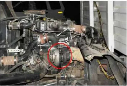
This type of data collection and matching is like on road test of the vehicle. This setup is available in the vehicle with the provision of placing engine with turbocharger and connecting sensors. It is a real time field data gathering instrument called as Data-logger. It is a computer aided digital data recorder which records the operating condition of the engine and turbo during the road test. The inputs are gathering from various parts of engine and turbo charger by sensors. The Graphtec make data logger is employed in this work. It is a computerized monitoring of the various process parameters by means of sensors and sophisticated instruments. The captured data are stored in the system and plot the operating points on the compressor map (plot of pressure ratio versus mass flow rate). The Fig. 1 depicts the setup for the data-logger testing in which the turbocharger is highlighted with red circle.
2.3 Decision Making
The decision making process is based on the position of the operating points on the compressor map. The map has a curved region like an expanded hairpin, in which the left extreme region is called surge region. The operating points fall on the curve or beyond, is said to be occurrence of the surge. That means the mass flow rate limit below the compressor limit. This causes a risk of flow reversal. The right extreme region curve is called as Choke region. The points fall on the curve and beyond its right side is denoted as the occurrence of choke. In the choke region the upper mass flow limit above compressor capacity, which causes the quick fall of compressor efficiency, Chances for compressor end oil leakage and insufficient air supply. The all operating points fall in between those extreme regions i.e., the heart region holds good. It must be ensured at all levels of operation of the engine holds good with the turbocharger. The manufacturer of Turbocharger provides the compressor map for each turbo charger based on its specifications
2.4 Engine Specifications
The TATA 497 TCIC -BS III engine is a common rail type diesel engine. It is commonly used for medium type commercial vehicle like Tata Ultra 912 & Tata Ultra 812 trucks. The engine develops 123.29 BHP at 2,400 rpm and also develops the peak torque of 400 Nm between 1,300 and 1,800 rpm. The other specifications can be found in Table 1.
Table -1: Specification of Engine
S.No Description Specifications
1 Fuel Injection Pump Electronic rotary type 2 Engine Rating 92 KW (125 PS)@2400 rpm
3 Torque 400 Nm @1300-1500rpm
4 No. of Cylinders 4 Cylinders in-line water cooled
5 Engine type DI Diesel Engine
6 Engine Bore / Engine Stroke 97 mm/128mm.
7 Engine speed 2400 rpm (Max power), 1400 rpm (Max Torque)
2.5 Turbochargers Specifications
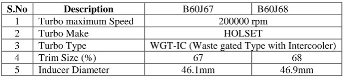
The TATA Short Haulage Truck and Turbochargers like B60J67 and B60J68 are considered to examine the performance of matching for TATA 497 TCIC -BS III engine. For example, if specification B60J67 means in which the B60 is the design code and J67 is the Trim Size or simply trim of the turbocharger in percentage. The other specifications furnished in Table 2.
Table -2: Specification of Turbo Charger B60J67 and B60J68
S.No Description B60J67 B60J68
1 Turbo maximum Speed 200000 rpm
2 Turbo Make HOLSET
3 Turbo Type WGT-IC (Waste gated Type with Intercooler)
4 Trim Size (%) 67 68
IJEDR1704132
International Journal of Engineering Development and Research (
www.ijedr.org
)
817
6 Exducer Diameter 68.8 mm 68.9 mm
III.EXPERIMENTAL OBSERVATION
The simulation and data-logger methods are adopted to analyze the turbo-matching of the Turbochargers B60J67 and B60J68 for the TATA 497 TCIC -BS III engine.
Figure 1 Experimental set up of Data-Logger method
Table-3: Simulated observations for B60J67 and B60J68 Turbo matching
Table- 4: Data-logger – Rough Road Route observations for B60J67 and B60J68 Turbo matching
Table -5 Data-logger – Highway Route observations for B60J67 and B60J68 Turbo matching
Table- 6: Data-logger – City Drive observations for B60J67 and B60J68 Turbo matching
S.No Engine Speed
(rpm)
Mass Flow Rate (Kg/sec.sqrt K/Mpa) Pressure Ratio
B60J67 B60J68 B60J67 B60J68
1 1000 10.67 11.449 1.783 1.856
2 1400 23.35 22.560 2.861 3.051
3 1800 30.81 29.451 3.401 3.556
4 2400 36.40 36.872 3.747 3.817
S.No Engine Speed
(rpm)
Mass Flow Rate (Kg/sec.sqrt K/Mpa) Pressure Ratio
B60J67 B60J68 B60J67 B60J68
1 1000 7.08 7.37 1.38 1.35
2 1400 15.11 15.41 1.98 1.95
3 1800 21.43 21.73 2.36 2.33
4 2400 27.09 27.43 2.58 2.55
S.No Engine Speed
(rpm)
Mass Flow Rate (Kg/sec.sqrt K/Mpa) Pressure Ratio
B60J67 B60J68 B60J67 B60J68
1 1000 7.84 8.12 1.38 1.35
2 1400 15.62 15.92 1.98 1.95
3 1800 21.57 21.87 2.36 2.33
4 2400 27.46 27.87 2.59 2.56
S.No Engine Speed
(rpm)
Mass Flow Rate (Kg/sec.sqrt K/Mpa) Pressure Ratio
B60J67 B60J68 B60J67 B60J68
1 1000 7.21 7.41 1.39 1.36
2 1400 15.32 15.52 1.98 1.95
3 1800 21.38 21.68 2.38 2.35
IJEDR1704132
International Journal of Engineering Development and Research (
www.ijedr.org
)
818
Table- 7 : Data-logger – Slope –Up observations for B60J67 and B60J68 Turbo matchingTable- 8: Data-logger – Slope –Down observations for B60J67 and B60J68 Turbo matching
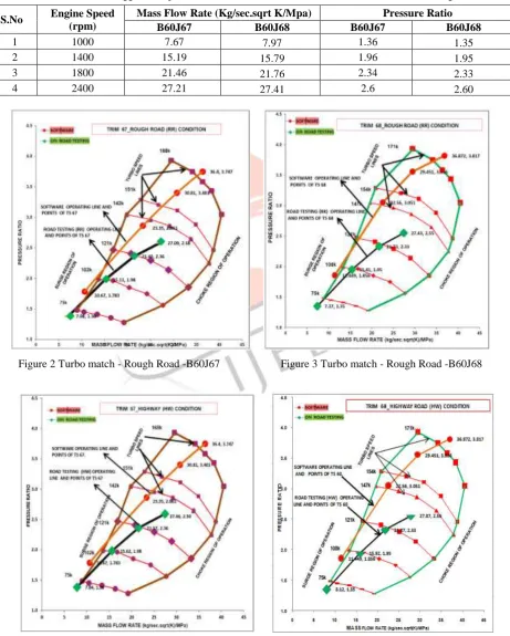
Figure 2 Turbo match - Rough Road -B60J67 Figure 3 Turbo match - Rough Road -B60J68
S.No Engine Speed
(rpm)
Mass Flow Rate (Kg/sec.sqrt K/Mpa) Pressure Ratio
B60J67 B60J68 B60J67 B60J68
1 1000 7.80 8.02 1.41 1.38
2 1400 15.51 15.81 2.04 2.00
3 1800 21.64 21.68 2.4 2.39
4 2400 27.77 27.39 2.64 2.62
S.No Engine Speed
(rpm)
Mass Flow Rate (Kg/sec.sqrt K/Mpa) Pressure Ratio
B60J67 B60J68 B60J67 B60J68
1 1000 7.67 7.97 1.36 1.35
2 1400 15.19 15.79 1.96 1.95
3 1800 21.46 21.76 2.34 2.33
IJEDR1704132
International Journal of Engineering Development and Research (
www.ijedr.org
)
819
Figure 4 Turbo match - Highway -B60J67 Figure 5 Turbo match - Highway -B60J68Figure.6 Turbo match- City Drive - B60J67 Figure.7 Turbo match –City Drive –B60J68
IJEDR1704132
International Journal of Engineering Development and Research (
www.ijedr.org
)
820
Figure 10 Turbo match – slope-down -B60J67 Figure 11 Turbo match - slope-down -B60J68The simulated matching performance obtained by use of manufacturer data. The desired combination is simulated at various speeds (1000, 1400, 1800 and 2400 rpm) to obtain the predicted operating conditions for this combination. The Pressure ratio and mass flow rates are important parameters to know the turbo matching performance. The simulated observations presented in the Table 3 for B60J67 and B60J68 Turbo matching. In datalogger method the turbocharger is connected to the TATA 497 TCIC -BS III Engine of TATA 1109 TRUCK with sensors. The vehicle loaded to rated capacity 7.4 tonnes of net weight. The grass weight of vehicle is 11 tonnes. The experimental setup for Data logger type matching shown in Fig. 1. The operating conditions collected while driving at a specific speed in the selected route For the same set of engine speeds the operating conditions were observed while vehicle driving in the routes like Rough Road, Highway, City Drive, Slope up and Slope down. The observations were recorded in the data-logger automatically through sensors and other sophisticated equipments. Those data logger observations were tabulated road condition wise from Table 4 to Table 8.
IV.RESULTS AND DISCUSSIONS
The operating conditions obtained for both turbo-chargers matching with engine. The observation of both simulated and data-logger at various road conditions like rough, highway, city drive, slope-up and slope-down, were marked in the respective compressor map. In the each graph the simulated matching performance shown for easy comparison and understanding. The Fig.2 and Fig.3 are for turbo-matching B60J67 turbocharger and B60J68 Turbochargers for TATA 497 TCIC -BS III Engine respectively for both methods especially at Rough Road route condition. Similarly Fig.4 and Fig.5 for Highway route, Fig.6 and Fig.7 for City Drive route, Fig.8 and Fig.9 for Slope up and Fig.10 and Fig.11 for Slope down. This
can be noted that all the graphs, at medium and higher speeds these two turbo-chargers combination with the desired engine ensure the safe operation and meeting the purpose well. But at lower speed, the surge occurred for when using
B60J67 turbochargers. In case of B60J68 turbo charger the operating conditions are nearby the line of surge. That is the risk of
flow reversal at lower speed for B60J67 turbo charger. Lower speeds cannot be avoided in the commercial vehicle. For
meeting the purpose, the adaption of B60J68 turbocharger is better than the B60J67 Turbocharger for the TATA 497 TCIC -BS III engine.
V.CONCLUSION
The turbo-matching of B60J67 turbocharger and B60J68 turbocharger for TATA 497 TCIC -BS III engine is considered. The
simulation method is employed to predict the turbo-match of B60J67 and B60J68 turbochargers individually with the
engine. The same was verified by experimental method called Data-logger at different routes. The simulator gives more values than the actual values obtained by experimentation. The results were deployed and presented with compressor map. The turbo match is found good at medium and higher speed for both turbochargers. But in the B60J67 turbo match surge found at lower speed. But in case of B60J68 not found exactly even though the vehicle operated at various routes. The simulated solution cannot be considered here for final decision. According to the data logger, the adaption of B60J68 turbocharger is better than the B60J67 turbocharger for the TATA 497 TCIC -BS III engine. The B60J67 turbocharger may be matched by increasing the minimum speed of the engine. The data-logger method adapted in this research may feel as expensive but it is one time job of finding the best turbo-match for an engine category.
ACKNOWLEDGMENT
The authors acknowledge M/s the Cummins Turbo Technology and ARAI, Pune, India for their support and contribution for this research work. The authors also acknowledge to the Dr.M.Chandrasekaran, Joint Supervisor, Professor & Director / Mechanical Engineering, Dr.C.Dhanasekaran, Professor & Head / Mechanical Engineering, Co-ordinator for School of Engineering, Vels University. Chennai., Dr.V.Muthukumar, Professor, Saveetha Engineering College, Chennai. And Dr.S.Santhanam, Professor, Rajalaskmi Engineering College, Chennai. TN. India., for their valuable suggestion to carried out this research.
REFERENCES
[1] G.Cantore, E.Mattarelli, and S.Fontanesi, "A New Concept of Supercharging Applied to High Speed DI Diesel Engines," SAE Technical Paper 2001-01-2485, 2001, doi:10.4271/2001-01-2485, 2001, pp.1-17.
[2] L.Guzzella, U.Wenger, and R.Martin, "IC-Engine Downsizing and Pressure-Wave Supercharging for Fuel Economy," SAE Technical Paper 2000-01-1019, 2000, doi: 10.4271/2000-01-1019, 2000, pp.1-7.
[3] B. Lecointe and G.Monnier, "Downsizing a Gasoline Engine Using Turbo charging with Direct Injection," SAE Technical Paper 2003-01-0542, 2003, doi: 10.4271/2003-01-0542, 2003, pp.1-12.
[4] S.Saulnier and S.Guilain, "Computational Study of Diesel Engine Downsizing Using Two-StageTurbocharging," SAE Technical Paper 2004-01-0929, 2004, doi: 10.4271/2004-01-0929, 2004, pp.1-9.
[5] T.Lake, J.Stokes, R.Murphy and R.Osborne, "Turbocharging Concepts for Downsized DI Gasoline Engines," SAE Technical Paper 2004-01-0036, 2004, doi: 10.4271/2004-01-0036, 2004, pp.1-13.
IJEDR1704132
International Journal of Engineering Development and Research (
www.ijedr.org
)
821
[7] A.Lefebvre and S.Guilain, "Modeling and Measurement of the Transient Response of a Turbocharged SI Engine," SAETechnical Paper 2005-01-0691, 2005, doi:10.4271/2005-01-0691, 2005, pp.1-15.
[8] S.Tashima, H.Okimoto, Y.Fujimoto, and M.Nakao, "Sequential Twin Turbocharged Rotary Engine of the Latest RX-7," SAE Technical Paper 941030, 1994, doi: 10.4271/941030, 1994, pp.1-10.
[9] T.Watanabe, T.Koike, H.Furukawa, N.Ikeya, "Development of Turbocharger for Improving Passenger Car Acceleration," SAE Technical Paper 960018, 1996, doi:10.4271/960018, 1996, pp.1-9.
[10]T.Kattwinkel, R.Weiss and J.Boeschlin, "Mechatronic Solution for Electronic Turbocharger," SAE Technical Paper 2003-01-0712, 2003, doi:10.4271/2003-2003-01-0712, 2003, pp.1-8.
[11]N.Ueda, N.Matsuda, M.Kamata, H.Sakai, "Proposal of New Supercharging System for Heavy Duty Vehicular Diesel and Simulation Results of Transient Characteristics," SAE Technical Paper 2001-01-0277, 2001, doi:10.4271/2001-01-0277, 2001, pp.1-9.
[12]J.Kawaguchi, K.Adachi, S.Kono and T.Kawakami, "Development of VFT (Variable Flow Turbocharger)," SAE Technical Paper 1999-01-1242, 1999, doi:10.4271/1999-01-1242, 1999, pp.1-8.
[13]C.Cantemir, "Twin Turbo Strategy Operation," SAE Technical Paper 2001-01-0666, 2001, doi: 10.4271/2001-01-0666, 2001, pp.1-11.
[14]C.Choi, S.Kwon and S.Cho, "Development of Fuel Consumption of Passenger Diesel Engine with 2 Stage Turbocharger," SAE Technical Paper 2006-01-0021, 2006, doi:10.4271/2006-01-0021, 2006, pp.1-9.
[15]J.Andersen, E.Karlsson and A.Gawell, "Variable Turbine Geometry on SI Engines," SAE Technical Paper 2006-01-0020, 2006, doi: 10.4271/2006-01-0020, 2006, pp.1-15.
[16]Z.Filipi, Y.Wang and D.Assanis, "Effect of Variable Geometry Turbine (VGT) on Diesel Engine and Vehicle System Transient Response," SAE Technical Paper 2001-01-1247, 2001, doi: 10.4271/2001-01-1247, 2001, pp.1-21.
[17]C.Brace, A.Cox, J.Hawley and N.Vaughan, et al., "Transient Investigation of Two Variable Geometry Turbochargers for Passenger Vehicle Diesel Engines," SAE Technical Paper 1999-01-1241, 1999, pp.1-17.
[18]S.Arnold, M.Groskreutz, S.Shahed and K.Slupski, "Advanced Variable Geometry Turbocharger for Diesel Engine Applications," SAE Technical Paper 2002-01-0161, 2002, doi:10.4271/2002-01-0161, 2002, pp. 1-12.
[19]Qingning Zhang, Andrew Pennycott, Chris J Brace, ‘A review of parallel and series turbocharging for the diesel engine’ Proceedings of the Institution of Mechanical Engineers, Part D: Journal of Automobile Engineering.Volume: 227 issue: 12, Sep. 2013, pp. 1723-1733.
[20]F.Millo, ,F.Mallamo and G.Mego,, "The Potential of Dual Stage Turbocharging and Miller Cycle for HD Diesel Engines," SAE Technical Paper 2005-01-0221, 2005, doi: 10.4271/2005-01-0221, 2005, pp. 1-12.
[21]N.Watson and M.S.Janota, Wiley-Interscience Ed. “Turbocharging the internal combustion engine”, Diesel motor – 1982, 608 pages.