ISSN (e): 2250-3021, ISSN (p): 2278-8719
Vol. 7, Issue 11 (November. 2017), ||V1|| PP 12-17
Design and Development of an Automatic Vehicle Gate Opener
Abu kebiru
1,
Engr. Mrs Obomeghie
Mariam
Abdul-Wajid
2(Department of electrical and computer engineering, Ahmadu Bello university, zaria, kaduna state, Nigeria.) ([email protected])
(Department of electrical/electronic engineering, federal polytechnic, Auchi, Edo State, Nigeria.)
ABSTRACT:
The automatic vehicle gate opener is an electronic-based project carried out to give a solution to a common problem encountered by people. It involves the design and construction of the transmitter circuit (using an infrared LED) and transmitting at a frequency of 30 kHz to 40 kHz. The receiver is a combination of an infrared receiver, a decoder IC to drive the relay. the output of the driver is fed to an NPN transistor which inverts the input to the decade counter CD4017 the output of the counting sequence fed to the transistor drivers which drives the relay to move the motor clockwise and anticlockwise to open and close the gate. A scaled-down prototype of the system was constructed on Vero-board and tested with a dc motor attached to the gate. The electronically controlled automatic vehicle gate opener could be used in homes, industries, classrooms etc for either convenience or safety reasons.KEYWORDS:
Design, construction, Automatic vehicle, Security, Gate opener--- --- Date of Submission: 11-11-2017 Date of acceptance: 25-11-2017 --- ---
I.
INTRODUCTION
Today’s technology emanates from the development in the field of electronic and the future has no limitation over this advancement in technology. To make life more interesting by reducing unnecessary waste of man-power, the proposed system was developed.
Having an automatic gate makes going in and coming out very easy, infact it is done at proximity depending on design and what is desired. These also add comfort to living by expunging the inconveniences of opening and closing a gate manually. It also serves as security to the car since infrared is installed in the car for it to open, whoever wants to steal it wouldn’t know what to do.
The primary aim of this work is to learn in details how the automatic gate system works and understand the concept involved. Another aim of this project is to fabricate and assemble a simple model to show how the gate system works. The main activities involved in this project are the research done on how the automatic gate works, sketching a detailed plan of the gate, welding /Arc welding the metal pieces together to form the gate, purchasing the correct power motor and circuit gate together and finally the test run.
Some of these works include the one done by [5] who design an automatic security gate, so also by [6] who made a great effort and also [7] to improve an automatic security gate. Another work of design and testing of remote by [3] on August 2006, which uses infrared sensors and the photodiode. Another work of design and construction of an infrared security light and alarm system was by [4] on March 2008. The control on Microsoft windows media player using an infrared remote control, a work done by [2] on March 2008. He improves the usage of infrared transmitter and receiver. Another work on design, control and testing of an infrared remote control system by [1] on October 2002, where he design a gate using infrared emitter driver.
The rest of the paper is organized as follows. In Section II we discuss the materials used and the block diagram of the entire system under consideration. In Section III, the evaluation /testing of the circuit was carried out. Section IV talks about the result and discussion. The paper culminates in section V with conclusions and future work.
II.
MATERIALS AND METHOD
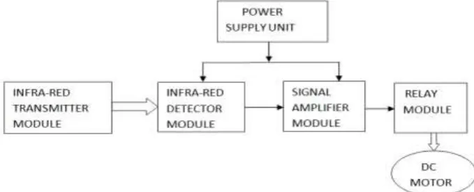
(receiver) [2]. Overall, the work employs the sensor, decade counter, Monostable multivibrator, 555 timers, resistors, capacitors, Astable multivibrator. The overall work was implemented with a constructed work, tested working and perfectly functional. This design could be used for security, also in industry for controlling substations, pump storage power stations and HVDC-plants. The block diagram of the entire system is depicted in fig 1 below. In Military, the usage of remotely controlled military vehicles, dates back to first half of 20th Century, Red Army used remotely controlled teletanks during 1930 and early stage of World war II. There were also remotely controlled cutters and experimental remotely controlled planes in the Army.
Figure 1. Block diagram of the automatic infra-red remote control system
2.1 Basis of Design
The receiver system comprises of a 9V DC motor, two relays and a rectangular aluminum bar. The rectangular aluminum bars provide the actual physical barrier. It slides to open or block the passage as may be required. The dimension of the rectangular aluminum bar is 35cm by 25cm. The assembly of the relays was attached to the entrance. Connecting wires are then used to link the integrated circuit (CD4017) from the relay to the DC motor since direct connection to the gate is not possible. Rectangular aluminum bar bars are chosen to ensure light load for the motor.
2.1.1 Infra-Red Transmitter Module
Infra-red (IR) radiation of wavelength is longer than that of visible light, but shorter than that of radio waves. The infrared transmitter has the ability to transmit infrared beam but can only travel in a rectilinear manner or line of sight, which is received by the infrared receiver at another end [8]. In recent years, there has being an increasing emphasis on the research, design and development of various infra-red devices, and system for military applications at night or during the day when vision diminished by fog, haze, smokes, or dust. One common way of realizing remote control is through the use of infra-red radiation. Many house hold electronics using remote control employs this method for switching, controlling, changing channels etc, depicted below in fig. 2 is the circuit diagram of the automatic infra-red remote control transmitter.
U1 LM555CN GND 1 DIS 7 OUT 3 RST 4 VCC 8 THR 6 CON 5 TRI 2 R1 1.0kΩ R2 2.2kΩ R4 470Ω R5 1.0kΩ Q1 2N3391Q2 2N3391 LED1 C1 0.01µF C2 0.001µF V1 9 V C3 100µF IC=16V R6 1.0kΩ . . Bus1Bus1
LED2
LED3
2.1.2 The Receiver Circuit
when the sensor detects the infrared signal from the vehicle, its output will drive a transistor which in turn provide a signal that triggers a Monostable multivibrator circuit made up of 555 timer/oscillator integrated circuit as the active component together with resistors and capacitor as the timing components. The output of the monostable multivibrator serves as the driver of the Astable multivibrator build using another 555 timer/oscillator IC. This astable multivibrator works as the clock source to a decade counter circuit made using an IC CD4017 which is a decade counter IC. The Q3 output of the counter is used for opening the gate, by driving a transistor that drives a relay that operates a dc motor that opens the gate. When the output of the counter reaches Q7 the output now operates another relay which this time drives the dc motor in the reverse direction to close the gate. As the output of the decade counter reaches Q9 the whole circuit resets and it wait for another trigger pulse to repeat the cycle. The general circuit diagram of the automatic vehicle gate opener is depicted in fig. 3 below
2.2 The Calculation on Monostable and Clock Sections
The Monostable Multivibrator circuit is designed using 555-timer /oscillator integrated circuit. It receives signals from the output of the transistor Q1. The duration of its output is determined by calculating its period as follows;
T = 1.1VR1C1
(1)
The VR1 is selected as 100k and C1 is taken as 47F. the period is calculated as; T = 1.1 x 100 x103 x 47 x 10-6
T = 5.17Sec.
The clock circuit is made using an Astable Multivibrator with 555 timer IC as the main oscillating device. The frequency of the circuit is given by the relation;
Where C1 = 22F, R5 = 10K and VR3 = 50K
F = 1.1Hz
2.3 Transistor Relay Drivers
The two relays that drive the motor forward and backward to open and close the gate are controlled using two transistors Q2 and Q3 each with a base resistor of 1k to limit the current from the output of the decade counter terminals. Each relay has a diode which is used for protecting the transistors from damage by the back E.m.f due to self induction of the coils of the relays. The diodes are 1N4001.
2.4 Transformer Selection
The transformer used in the design is sourced locally from an electronic shop. It is a step down transformer having a rating of 200-240volt, 50Hz, 500mA. The transformer converts the mains 220-240V to a step down voltage of 12V. Therefore the specification of the chosen transformer is as follows:
Primary voltage =240V Secondary voltage =12V Power rating = 6VA Current rating = 500ma
2.5 Capacitor Selection
Filtering establishes a steady state direct current supply by smoothing the voltage output of a rectifier and eliminating the a.c components. The choice of a smoothing capacitor can be determined with the supply frequency of 50Hz.
(2)
C= capacitor F= frequency
Vdc = d.c voltage from transformer Rl = load resistance
Vr = ripple voltage Vr =Vp -Vrms
Vp = 2Vrms = x 12 =16.9
Vr = 16.912 = 4.9V
2.6 Bridge Rectifier
The four diodes full-wave bridge rectifier used has the following ratings maximum rating = 60v Maximum forward current=1.5A
The peak value of the full-wave signal is Vp
VP =
(3) Vrms =12
VP = x12
VP =16.9V
2.7 Selection of Relay
The relay selected from the relay manufacturer’s specification sheet has the following properties: V=12V
R=200
2.8 Peak Inverse Voltage (Piv)
The full wave rectifying circuit PIV is defined as the maximum voltage that occurs across the rectifying diode in the reverse direction. For full wave bridge rectifier employ in this project, the PIV rating of the diode to be chosen should be greater than 1.5-3 times the value of Vp.
PIV of diode =
(4)
=1.5 x 12 = 25.4V.
2.9 Filtration
This is the process by which fluctuating or pulsating (ripple) present in the output voltage supplied by the rectifier is being removed using a filter. A capacitor filter is used in this circuit, which consist of single capacitor connected across the pulsating direct current (dc) which smoothens out the voltage pulsations. The effectiveness of the capacitor filter is determined by three factors: The ripple factor, the size of the capacitor and the load value
From the relation: Vr = IdcXc
Then, (5)
(6)
Where,
Vr = ripple voltage
Vpp = peak-to-peak voltage
Vrms = root mean square voltage
Hence,
(7)
(8)
=
= 1.8A (2A is recommended).
III.
EVALUATION/TESTING OF CIRCUIT
Prior to power up, the circuit board assembly was checked for poor soldered connections and possible short-circuits between closely spaced components. When this was established absent, Power was fed to the circuit for a short time and then cut off using the finger as a heat sensor, the temperature of the components were felt to see if any was overheating. When this was satisfied that there was none, the switch was then completely turned out. Voltage test was then followed. This was performed with a digital voltmeter. Voltage level at different points on the board was taken and compared with the design specification of 12V. A close march of 11.96V was established with a difference of 0.04V.
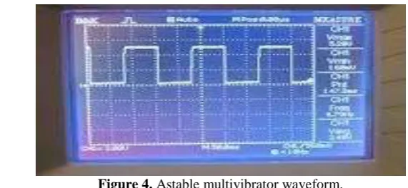
Figure 4. Astable multivibrator waveform.
IV.
RESULTS AND DISCUSSIONS
This work, design and development of automatic gate opener system is developed as per the design and the waveform in figure 4 depicts that the system is perfectly working. It is an extremely valuable project. This project introduces a new way to automate a gate, in the sense that, it provides a means of saving people the stress of undergoing continuous and very tedious work of manually opening and closing the gates for the passage of the vehicles.
V.
CONCLUSION
The design and development of the automatic gate opener had been achieved in this work. This design can be easily adapted to any electric gate and any form of control which requires the use of sensors, where it was used to detect the infrared signal from the approaching vehicle and then activates the motor to open the gate automatically and then closes the gate when the vehicle had passed.
It gives value to the job of officers manning the gate and enhances their performances. Also, when deployed in a car park it can reduces the required number of officers manning a gate thereby creating room for better and efficient utilization of available workforce to an organization. The automatic gate system is not difficult to develop and the components/modules are readily available in the market. Field deployment only requires a bigger motor that has gear to effectively and efficiently hold firm the bar that constitute the physical barrier.
REFERENCES
[1]. Alvin Gandy of Eden, Tx in 1965.[5]
[2]. Keith G. vicker. (2010). Free Home made automatic gate opener plans,7 may update[6] [3]. Rhodes for US patent issue on April 7, 1992. [7]
[4]. Malgwi T.J (2006), "Design and testing of a remote control”, on August, final year project submitted to the department of electrical engineering, Ahmadu Bello University Zaria.[3]
[5]. Ahmad J.H (2008), “Design and construction of an infrared security light and alarm system” done on March, final year project submitted to the department of electrical engineering, Ahmadu Bello University Zaria.[4]
[6]. Ajene P.B (2008), “The control of Microsoft windows media player using an infrared remote control” on March, final year project submitted to the department of electrical engineering, Ahmadu Bello University Zaria.[2]
[7]. Popoola T.A (2002), “Design, construction and testing of an infrared remote control system” on October, final year project submitted to the department of electrical engineering, Ahmadu Bello University Zaria.[1]
[8]. Shoewu. O. and Segun O. (2013),”Design and implementation of a microcontroller based Automatic gate” African journal of computing & ICT. vol. No.1, March.[8]