Modified CMOS Multiplication Algorithm Using
Optimized Array Structure
P. Assadee
Islamic Azad University Varamin branch [email protected]
Abstract—In this paper, a new, high-speed multiplication algorithm using tree circuit and a novel inner product generator has been presented. In inner product generation step, a new Smith algorithm has been modified. In inner product reduction step, a new array structure has been proposed. In final addition step, a new algorithm has been used. In this work, improvements in multiplication algorithm by using a faster counter along the tree are presented. In this paper, the novel presented multiplication algorithm has been also analyzed in comparison with other multiplication algorithms. Based on the variation of inner product generator methods, a novel Smith algorithm is proposed. This work, presents a novel approach to reduce power of high-speed multiplication algorithm based on decreasing number of inner products. The reducing elements used into the multiplication algorithm architecture remove some inner product that have not effect in final addition. The proposed array structure and Smith algorithm has major effect in multiplication algorithm performance. Previous designs have been used to present a novel structure. A new multiplication algorithm is designed and simulated in 80 nm process. We used SPICE and some programming code for simulations. The latency has decreased by almost 15 percent and power consumption decreased by 14 percent. Our design reduced transistor count by 10 percent.
Index Terms— CMOS, Counter, inner product, Smith algorithm, VLSI
I. INTRODUCTION
Multiplication has three important steps that include inner product generation, inner product reduction and final addition. High-speed multiplication algorithms are important arithmetic components for processors and digital signal processing and other computational applications. To achieve high-speed designs, parallel multiplication algorithms are widely used. Due to transistor count and large operands, these structures become the most power-consuming parts in modern processors circuits. As a result modifying the multiplication algorithms for power consumption and speed is important. Tree multiplication algorithms present high speed in processors but they are difficult to layout because of their non-regularity, which also results to high power consumption. Array multiplication algorithms (which may use the various inner product generator algorithms) have good regularity but do not have the performance of the high-speed operators. The recursive
high-speed multiplication algorithm uses a novel algorithm because its performance is like to a Dadda or a Wallace multiplication algorithm but it has regular structure. The difficulty in implementing this method is its complexity. This paper presents and evaluates the problems in the architecture of the conventional multiplication algorithm and presents methods to decrease the complexity.
In many computational problems, the "divide-and-conquer" algorithm is used to solve large problems to smaller problems. This method can be used in multiplication algorithms for increasing performance and breaking the multiplication into smaller slices and using smaller multiplication algorithms. Many of the previous algorithms use this algorithm in two ways. One method is to divide the multiplication into a number of slices, such as different rows of the multiplication structure that are performed concurrently [1,2,3]. Another way is to use a smaller multiplication algorithm at the first steps and then merge the results. The recursive multiplication algorithms are in this group. Some multiplication algorithms that use this algorithm use counters to obtain result from small multiplication algorithms [4,5,6]. Since these counters have delay of O(n), this does not increase the speed of the multiplication algorithm. The algorithms that are in the first collection do not have regularity and the simplicity of the multiplication algorithms as the other group.
II.MODIFIED ARRAY MULTIPLICATION ALGORITHM
For the W – m least significant bits of the operands unsigned multiplication can be done. The inner product parts at the left and bottom of the tree need to be different to hold the sign of the operands.
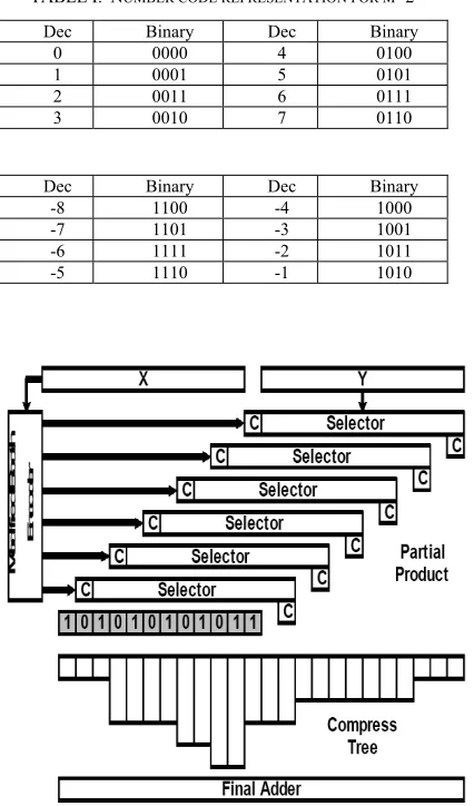
In Figure 1 we show that the sign extension is presented in mix method (10 for a non-positive number). Note that for the mix structure, three kinds of parts are necessary. Kind I is the part for the operation of unsigned values. Kind II part does the m-bit inner product of an unsigned value with a number value. Finally, kind III part that operate on two signed values. Only one kind III part is necessary for any kind of multiplication algorithm,
whereas 2w 2Kind
m − II parts and
2 (W 1) Kind
m − I
modules are needed. The mix multiplication algorithm structure using these parts will be proposed in the next section. This new structure decreases the critical path of array structures.
III. MIX MULTIPLICATION ALGORITHM USING CARRY SAVE COUNTER
The operation of a number mix multiplication using carry save counter for the summation of inner product expressions, for operators with W=6 bits using radix-4 (m=2), is presented in Figure 2. For the example presented, the inner product expressions are calculated by multiplying each 2-bit group of the multiplication algorithm and multiplicand expressions. Thus, each inner product is calculated by a 2*6 multiplication as shown in Figure 2. The final product for the modular radix multiplication is calculated by adding each 2-bit group of the inner product expressions in a carry save outline, as shown in Figure 2. It should be useful that only the final grouping of the final carry and sum needs a chain carry addition. In the chain addition operation, the two most significant bits must be deleted. To make the array more regular we use a sign addition technique where two extra bits are used in the inner product. Note that we enlarge the signal as 10 that shows a non-positive number (-1) in the mix operation.
IV. MODIFIED SMITH MULTIPLICATION ALGORITHM
Think about the multiplication of an n-bit
multiplicand 1 2
12 0 2
n
n i
n i i
X x − − x
− =
= − +
∑
and multiply2 1
12 0 2
n
n i
n i i
Y y − − y
− =
= − +
∑
. By modified partial product generator (PPG) algorithm, multiply Y is shown as2 2i i
Y =
∑
y′ where the modified Smith determined digiti y′is
2 1 2 2 1
2
i i i i
y′ = − y + +y +y −
Figure 2. Number mix multiplication using carry save counter
TABLE I. NUMBER CODE REPRESENTATION FOR M=2 Dec Binary Dec Binary
0 0000 4 0100 1 0001 5 0101 2 0011 6 0111 3 0010 7 0110
Dec Binary Dec Binary -8 1100 -4 1000 -7 1101 -3 1001 -6 1111 -2 1011 -5 1110 -1 1010
Note that, in the previous equation, yi′can have one of the five values {0, 1, 2± ± }. Each determined expression is used to choose a multiple of the multiplicand to generate a inner product. Table II presents the presented PPG algorithm table, where Xiand 2Xi signals present whether inner product is double or not, and Nishows the negation of inner product. Although modified PPG algorithm decreases the number of inner products powerfully, the decreasing is obtained with the operating cost of transformer and inner product production circuit. Figure 3(a) presents the interconnection of transformers and inner product bit production circuits for a 6*6 modified PPG multiplication algorithm. In the PPG transformer of Figure 3(b), the three PPG determined bits Xi, 2Xi and Niare produced from the three neighboring multiplication algorithm bits y2i+1, y2i , and y2i−1.
Since the value of modified PPG determined bit yi′is 2
2 times larger than that of yi′−1, the sum of two neighboring PPG determined digits can be shown as
If the PPG determined bit pair is showed as 1
[ ,y yi′ ′i− ]can be showed as
For example, the pair [-1,2] and [1,-2] can be show as [0,-2] (k=-1) and [0,2] (k=1), respectively. Also, by consecutively applying (4) from left to right, a group of more than two PPG determined bits can be changed to new group as
V.INNER PRODUCT REDUCTION TECHNIQUE
The main idea of our work is based on the study that most modern multiplication algorithms generate a large number of bit transitions while adding zero inner products [7,8,9]. Consider a general m by n multiplication of two unsigned numbers X =Xn−1...X0 and
1... 0 m Y =Y − Y (
1 1
0 2 , 0 2
i m i i n i
i i
i i
Y =
∑
= −= Y X =∑
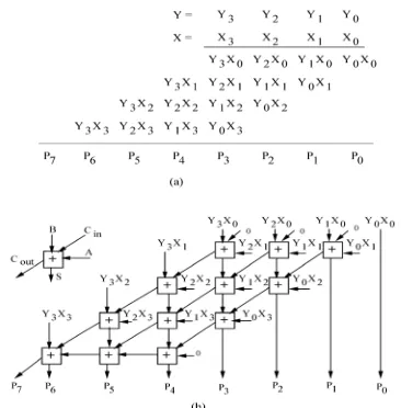
= −= X ). The product P=P2n−1...P P1 0 results Figure 3(a) shows an example of a 4*4 multiplication. From multiplying the multiplicand, Y by the multiply X can be written as follows:In previous array multiplication algorithms, the inner products Pk =Y Xi. j are produced in parallel with AND gates, and then added in array of 1-bit counters. Figure 3(b) shows the 4*4 array multiplication algorithm. Such
Figure 3. (a) Multiplication X*Y (b) multiplication algorithm array
TABLEII.MODIFIED PPG ENCODING
2i 1
y + y2i y2 1i− yi′
0 0 0 0 0 0 1 1 0 1 0 2 0 1 1 -2 1 0 0 -1 1 0 1 -1 1 1 0 -1 1 1 1 0
i
X 2Xi Ni
0 0 0 1 0 0 0 1 0 0 1 1 1 0 1 1 0 1 1 0 1 0 0 0
an m*n multiplication algorithm needs m*(n-1) counters and n*m gates. The multiplication algorithm depth relates to the word length n of the operand X.
Conventionally, the switch action of the multiplication algorithm is weakly associated with X. In particular, if the j-th bit of X is 0, the j-th row of counters does not need to be activated, since the consequent inner product is 0. The counters of the conventional array multiplication algorithm, however, make summation of the zero inner products and, as result, show redundant signal change. The increased activity of the internal components results in unnecessary power dissipation. To remove the redundant signal changes, we would disable the counters whose inner product is zero while shifting and moving the inner product of the previous counter rows to the nest row of counters.
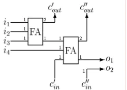
Figure 4 shows an implementation method of the presented approach on example of 4*4-array multiplication algorithm. In comparison to conventional multiplication algorithm structure [10,11,12,13], the method includes n*m adding cells, modified to disable unnecessary transitions and move the inputs to outputs when the parallel inner product is zero. The internal structure of the adding cell is shown in Figure 5.
Two multiplexers added to the outputs of the counter send out the carry-input and the sum of the previous addition to the outputs, when the next bit Xiis zero. The high-speed buffers, placed at the inputs of the counter cell, disable signal transitions in those adding cells that are moved. The output carry-bits are passed to bottom of the array, instead of to the right.
In general case of m*n multiplication, the multiplication algorithm includes m*n AND gates, (m-1)*(n-1) adding components, 2*(m-(m-1)*(n-1) multiplexers, and (m+n-2) counter units to generate the result. For the given multiplicand Y, the worst-case critical path delay of the multiplication algorithm is given by:
Where Dadd, Dac are the spread delays between the input and carry output of the conventional one counter and the adding cell; Dmuxand Dand are the multiplexer delay and the AND gate delay, respectively, Nnzis the number of non-zero bits in X.
VI. CONCLUSIONS
A new high-speed low-power multiplication algorithm has been presented. In inner product generation step, a new PPG algorithm has been modified. In inner product reduction step, a new array structure has been proposed. In final addition step, a new algorithm has been used. This paper proposed a novel technique for decreasing power consumption of digital multiplication algorithm. The technique uses removing of counters when the inner products are zeros, thus results more efficient computation. We have presented a mix array multiplication algorithm that operates on numbers using
carry save counters in order to speed-up the inner product counter along the array. We have presented that the use of carry save counters in the inner product reduction step of the multiplication algorithms generates significant improvement in area, delay and power consumption when compared against other multiplication algorithms. Based on the different modified PPG algorithm methods, efficient modified PPG multiplication algorithm for prearranged groups was proposed. In multiplication algorithm design, there is often a trade-off between the complexity and the speed. Each design will have its own specific requirements, which need to be satisfied by the design choice. Some of the comparisons can be done with the selection of different base multiplication algorithms. To obtain more performance, a Dadda multiplication algorithm can be used as the base multiplication algorithm, but this increases the difficulty. The modified reduction cells introduced in this paper decrease the complexity of the reduction steps. Simulations have been done with SPICE and programming codes. The proposed Array structure and PPG algorithm has major effect in multiplication algorithm performance. Previous designs have been used to present a novel structure. Table III shows comparisons between multiplication algorithms. The latency has decreased by almost 15 percent and power consumption decreased by 14 percent. Our design reduced transistor count by 10 percent.
REFERENCES
[1] Kang, J.Y. and J.L. Gaudiot, "A simple high-speed
multiplier design", IEEE transcactions on computers, vol. 55, no. 10, October 2006.
[2] Kang, J.Y. and J.L. Gaudiot, "A fast and well-structured
multiplier", EUROMICRO Symp. Digital System Design, pp. 508-515, Aug, 2004.
[3] Maundy, B. and P. Aronhime, "Useful multipliers for
low-voltage applications", in Proc. IEEE Int. Symp. Circuits and Systems, vol. 1, pp. 737-740, May 2002.
Figure 5. Internal architecture of counter
TABLEIII.COMPARISON BETWEEN 32×32 BIT MULTIPLIERS
Multipliers Present study [10,11,12] [13,14,15]
Technology (nm) 80 80 80
Transistor counts 21288 24322 28914
Multiplication time
(ns) 2.5 3.1 3.5
Chip Area ( 2
mm ) 0.35 0.42 0.57
Power Diss.
(mW/MHz) 0.31 0.44 0.61
[4] Fried, R., "Minimizing energy dissipation in high-speed multipliers", in Proc. IEEE Int. Symp. Low Power Electronics and Design, pp. 214-219, 1997.
[5] Tenca, A.F., G. Todorv and C.K. Koc, "High radix design
of a scalable modular multiplier", in Cryptographic hardware and embedded systems-CHES, 2001.
[6] Jou, J., "Design of low-error fixed-width multipliers for
DSP applications", IEEE Trans. Circuit. System., vol. 46, no. 6, pp: 836-842, 1999.
[7] Hang Z., "A new high-performance low-power
multiplier", JSSCC 2002.
[8] Fonca, M. and E. Cossat, "Design of array multiplier using
high-speed adders", in Cryptographic hardware and embedded systems-CHES, 2001.
[9] Keem, Y. and J. Kung, "Low power Booth multiplier", in
Cryptographic hardware and embedded systems-CHES 2001.
[10] Keem, S. and C.H. Ziesler, "Design verification and test of
a true single-phase 8-bit adiabatic multiplier", in Proc. 19th
Conf. Advanced Researh VLSI, Salt Lake City, pp. 42-58, Mar. 2001.
[11] Rong, L., "A run-time reconfigurable array of multipliers
architecture", in Proc. Of 8th reconfigurable architectures
workshop, 2001.
[12] Oban, J. and V. Moshen, "Multiplier power reduction
through removing of partial products", Proc. Midwest Symposium on Circuits and systems, 2000.
[13] Keem, J. and E. Swart, "Improving high-speed multiplier",
IEICE 2005.
[14] Peetra, N., "A novel architecture for multipliers", IEEE
Trans. Comput., vol. 56, no. 11, pp: 1471-1482, 2007.
[15] Van, L., "Generalized fixed-width multipliers", IEEE