The Effect of Shape Optimization and
Bimaterial Stem on Increasing the Performance
of a Cemented Tibia
N. Fouda
Mansoura University, Faculty of Engineering, Mansoura, Egypt
[email protected] Abstract--
The stem design, geometry and material change the
mechanical behavior of bone around tibia tray and stem after TKA. In this study a shape optimization of a cemented tibia stem has been carried out to solve the stress shielding at the proximal tibia as well as the stress concentration at the stem tip. It is found that the optimal shape is a short stem with small diameter at the distal stem tip increased gradually to reach a maximum value at the proximal tibia stem. This optimal shape is increased von Mises stress at the lateral and medial cancellous bone by 130% and 140%, respectively compared to initial stem shape. On the other hand the stress concentration in bone at stem tip using the optimal stem shape is reduced by 25% compared to initial shape. However, the optimal stem shape is reduced the stresses in cement at stem tip by 28% laterally and 17% medially compared to the initial stem shape. Finally, a bimaterial stem (titanium with a polymer stem tip) has been applied to the optimal shape to improve the stress concentration reduction at the stem tip. The results are approximately the same compared to the optimal titanium stem shape.
Index Term-- Knee replacement, shape optimization, von Mises stress, stress shielding, bimaterial, finite element analysis.
1. INTRODUCTION
After knee replacement surgery the stiffer implant carries the majority of the load, which was actually carried by the bone itself before implantation. The resulting implant induced stress-shielding and subsequent bone remodeling causes bone resorption around the implant especially at the proximal part of the knee under the tibia tray [1]. Stem tip pain following revision total knee arthroplasty is a significant cause of patient dissatisfaction, which in the presence of an aseptic well-fixed component has no widely accepted surgical solution. A definitive cause of stem tip pain remains elusive, however it has been suggested that high stress concentrations within the region of the stem tip may play a role. [2, 3]. Geometry and material property optimization represent the possible methods of using prosthesis stiffness for alignment with bone stiffness and increasing total knee replacement lifespan. Material optimization has studied previously by Hedia and Fouda [4] using the concept of functionally graded material in the design of cementless tibia. However the effect of geometry optimization as well as using a biomaterial stem will be studied in this analysis.
Finite element analysis has been widely used in many areas of biomedical engineering. Design optimization uses numerical algorithms to determine the best design for a given application. The optimum design yields the best performance with respect to a given performance measure (objective function) and simultaneously satisfies any performance or design space limitations (equality and inequality constraints)
[5]. Completo et. al. [6] in their study support that short stems produce a minor effect in bone relative to long stem in terms of stress shielding and stress concentration at tip region. Overall, all stems provoked high stress concentrations in bone at the tip of the stem. A plate is attached to the tibia within the region of the stem tip to reduce stem tip pain which is analyzed by Kimpton et. al. [7]. Their results demonstrate that the plate reduces stress concentrations in the bone at the stem tip of the implant. The magnitude of stress reduction is dependent upon plate location, material and attachment method. A parametric study investigated the effects of prosthesis fixation design changes, which included the presence, length and diameter of a central stem, the use of fixation pegs beneath the tray, all-polyethylene versus metal-backed tray, prosthesis material stiffness, and cement mantle thickness [3]. It is concluded that design features such as longer stems reduced bone and bone–cement interfacial stresses thus the risk of loosening is potentially minimized, but at the expense of an increased tendency for bone resorption. The stress level at the interface of the tibia and femoral component is lower for increased sagittal radius, as concluded by Mallesh and Sanjay [8]. Shear stress and von Mises stresses are increased with increase in the flexion angle which is to be optimized. A parametric analysis of fixation post shape in tibial knee prostheses has been studied by Au et. al. [9]. In terms of interface forces, a tapered post decreased post shear while slightly increasing post compression compared to a cylindrical post. The optimization of the geometry of an UHMWPE type of knee implant in the sagittal plane with minimum amount of wear was investigated by Dargahi et. al. [10]. The effect of stem length, diameter, and mode of fixation on the motion and stress transfer of a cemented tibial tray for 12 cadaver knees were evaluated by Jazrawi et. al. [11]. There was a significant decrease in motion of the tibial tray with increasing press-fit stem length (75–150 mm) and increasing stem diameter (10–14 mm). Cemented tibial stems showed significantly less tray motion than uncemented stems. Hedia et al. [12, 13] investigated the following points: 1- A Method for Shape Optimization of a Hip Prosthesis to Maximize the fatigue life of the cement [12], 2- Shape Optimization of Charnley prosthesis based on the fatigue notch factor[13]. They concluded that the optimal shape reduces the stress shielding and the interface stresses. Consequently, the fatigue life of hip prostheses was increased.
2. MATERIAL AND METHOD
2.1. Model Geometry and Finite Element Analysis
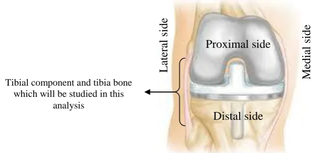
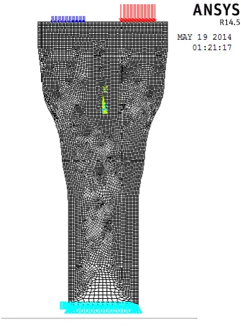
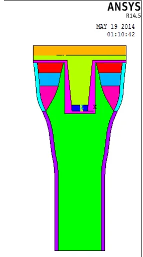
The total knee replacement joint consists of a tibial base plate or tray, usually made of titanium alloys, stainless steel or cobalt chromium molybdenum (CoCrMo), with a tibial insert (UHMWPE) that acts as the bearing surface. The details of the total knee components and these components which are inserted in a knee joint are illustrated in Fig. 1(a, b). In this analysis a two-dimensional finite element model was used to represent a section of the mid – coronal plane of the tibia with a cemented prosthesis implanted. Fig. 2 (a) represents this cross section to clear the tibial component with a polyethylene which will be studied in this analysis. ANSYS 14.5 software package was used to create the finite element model. The finite element model was created using linear isoparametric quadrilateral and triangular elements, with approximately 7956 elements for all model components. In normal conditions, the knee joint receives load of up to two to three times the body weight, while the maximum load it can sustain is eight times the body weight. This study was considered the load of three times the body weight, which is typical during normal level walking [14, 15]. The weight over single knee is only half the maximum load as the load is shared between the two knee joints. 60% and 40% of the total load was applied to the medial and lateral condyle nodes, respectively (the medial and lateral sides of the joint are shown in Fig. 1). This load distribution simulates the situation that has been reported to be experienced during the stance phase of walking in the case of a person with a mass of 70 kg [16]. The tibia was assumed to be rigidly fixed in all directions of the distal part (the distal and proximal sides of the joint are shown in Fig. 1). The finite element model and the loading conditions were represented in Fig. 3. The tibial model consisted of the tibial bone (cortical and cancellous), the tibial tray, cement mantle (PMMA), and the ultra high molecular weight polyethylene (UHMWPE) insert. Linear elastic behavior was assumed for all materials. The heterogeneous material properties of the bone were modeled with six sections of different modulus (cortical diaphyseal, cortical metaphyseal, cancellous epiphyseal, cancellous metaphyseal 1 and 2, and cancellous diaphyseal) [3, 14, 17]. The tibia was made of titanium alloy. The properties of all materials were listed in table 1. The tibia represented knee with a medial – lateral width of 74 mm, the tibial plate height equals 8mm. The initial design of the stem length is 40mm and stem diameter is 12mm. The initial design of all prosthesis components was shown in Fig. 4.
The large difference between the stiffness of the metal implant and the surrounding bone is the main cause of stress shielding under the tibia tray. Another problem observed after TKA is the stress concentration which is appeared at the distal region of the metallic stem. Therefore the objective of this analysis is to optimize the shape of the metallic tibia stem in order to solve the conflicting problems of stress shielding proximally, and the stress concentration distally, as well as decreasing the interface shear stress between the model and the surrounding bone.
2.2. Shape Optimization of the Cemented Tibia Tray
In applying the numerical shape optimization procedure, we define a particular desired stress distribution and determine the design which would realize the objective as
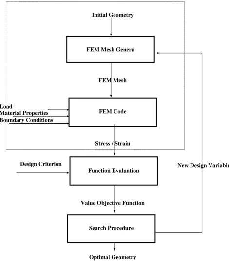
good as possible. The principle of the mathematical characteristics of the numerical shape optimization procedure is based in an iterative computer process in which the FEM model is integrated schematically represented in Fig. 5 [18]. The process is started with an initial design for which stresses, strains, or other mechanical variables are determined with the FEM model. If the stress distributions deviate from the desired optimal ones, the design (and hence the FEM mesh) is slightly adapted in such a way that the stresses change in a more favorable direction, and the process is repeated until the desired (optimal) stress patterns are approximated as good as possible. The way in which the shape of the prosthesis must be adapted in each iteration is determined in a “search procedure” which determines the search direction [19]. The stress components to be minimized are combined in a so-called “objective function”. In the iterative process, the value of this function is actually minimized, in the sense that the particular shape evolves, rendering this function its minimal value. Also we must include a check against unrealistic shapes, for that reason the so-called “boundary constraints” are accounted for in the NSO procedure. Finally the shape variations considered in a particular process are limited to a particular “design space”. In other words, the allowable shape variations must be well defined. They are bounded by the above-mentioned “boundary constraints” and, within these boundaries, defined by the so-called “design variables”.
The initial stem shape in this study is 40mm length and 12mm diameter. In order to have the optimal stem shape the optimization technique applied through the ANSYS package. The computer program was written using the Ansys Parametric Design Language APDL to find the optimal stem shape. The optimization technique analysis for this study is:
a.Objective Function: to minimize the von Mises stress at the distal part of the cancellous
diaphyseal bone Minimize σ distal
diaphyseal bone
b.Design Variables:
(1) Change the proximal stem diameter (D1) and the distal stem diameter (D2) within values obtained from literature. 12 mm ≤ D1, D2 ≤
20 mm
(2) Change the length of the stem within values obtained from literature.
30 mm ≤ L ≤ 120mm
c.State Variables:
(1) The maximum von Mises stress in the lateral and medial cancellous epiphyseal bone to be more than the maximum von Mises stress using the initial shape of titanium tibia. However, it is maximum value does not exceed the value of von Mises stress at this part of tibial natural bone.
σ epiphyseal bone initial ≤ σ epiphyseal bone optimal ≤ σ natural tibial epiphyseal bone (2) The maximum von Mises stress in the lateral
maximum value does not exceed the value of von Mises stress at this part of tibial natural bone.
σ diaphyseal bone initial ≤ σ diaphyseal bone optimal ≤ σ natural tibial diaphyseal bone (3) The maximum interface shear stress in the
lateral and medial cement at cancellous bone /cement interface to be less than the maximum interface shear stress using initial cemented titanium tibia. However, its minimum value is an arbitrary small value (e.g. 0.01Mpa).
τ arbitrary value ≤ τ cement optimal ≤ τ cement initial
3. RESULTS AND DISCUSSION
In order to check the validity and limitations of the 2D finite element model, the results obtained from this model before optimum design were compared with the results obtained from more detailed 3D – finite element model [20]. Also, a comparison between the results of this model before optimum design was compared with other 2D models that have been carried out through other studies [3, 17] which have approximately the same properties, dimensions, and the same loading conditions. There is a good agreement in von Mises stresses between the model of this study and those other models. The stress values are not exactly identical, but the trends of the stresses in each model are significantly similar.
Starting from initial stem shape with 12 mm diameter and 40 mm length, the optimization process was continued until the last run. The optimal stem length was found to be 40 mm and the diameter changed from 12 mm at the distal part of stem to 20 mm at the proximal part of stem. The optimal shape was illustrated in Fig. 6. Then the idea of using the stem as a bimaterial was applied to the optimal shape in order to improve the reduction of the stress concentration at the distal stem tip which was obtained from the optimal stem shape. Therefore, the effect of made the optimal stem shape as a bimaterial was also studied. The optimal stem shape was made of titanium and a polymer material at the stem tip, as illustrated in Fig. 7. The effect of using the optimal stem shape with and without a polymer tip on solving the stress distribution problems which is occurred after TKA will be illustrated through the following results:
von Mises stress distribution in the lateral and medial epiphyseal cancellous bone at cement / bone interface was illustrated in Fig. 8 and Fig. 9, respectively. The stresses were decreased gradually towards the tibia stem for both lateral and medial interfaces. This stress reduction is due to the decrease in the elastic modulus values from the cortical bone to diaphyseal bone through epiphyseal bone. There was no difference of stress distribution between the initial stem shape, the optimal stem shape, and the optimal stem shape with the polymer tip.
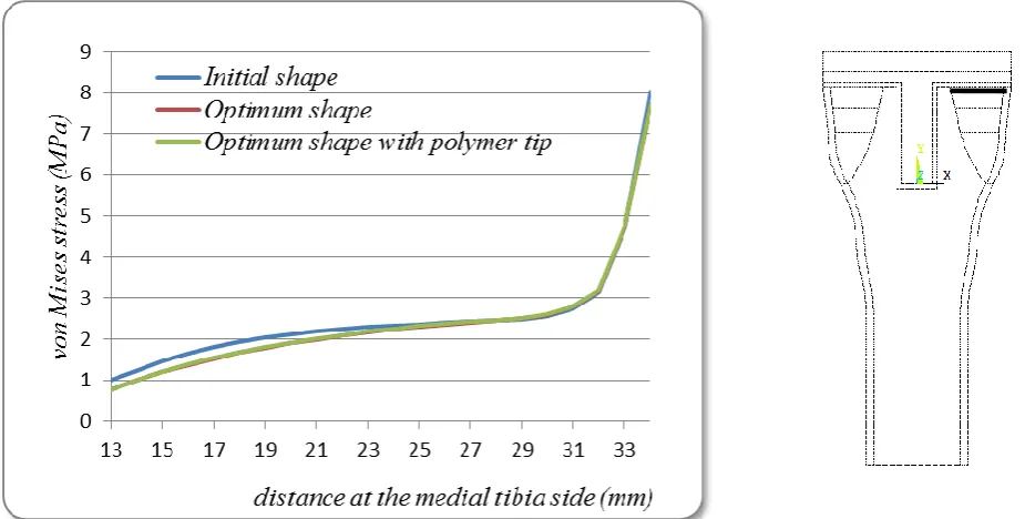
von Mises stress distribution in the lateral diaphyseal bone at cement / bone interface was illustrated in Fig. 10. It was found that the stress was increased gradually for the optimal stem shape from 16% near the tibia stem to 130% compared to the stem initial shape. This percentage was not
making a big difference using the optimal shape with a polymer tip. The stress increased for the optimal shape with polymer, from 20% to 140% compared to the stem initial shape.
Fig. 11 was illustrated von Mises stress distribution in the medial diaphyseal cancellous bone at cement / bone interface. The optimal shape was increased the stress gradually from 8% to 140% compared to the stem initial shape. However, using the optimal shape with a polymer tip was increased the stress from 10% to 150% compared to the stem initial shape.
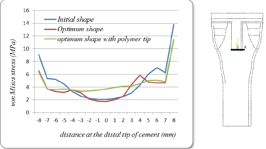
von Mises stress in bone at the distal stem tip at cement / bone interface was illustrated in Fig. 12. The stresses were represented from the lateral to the medial interface. It was observed that the stresses along the entire stem tip were decreased with the optimal stem shape and with the optimal stem with polymer compared to the initial stem shape. It was found that the maximum stress reduction was occurred at the lateral side. The maximum von Mises stress was decreased by 25% for the optimal stem shape and by 26% for the optimal shape with polymer tip compared with the initial stem shape. The interface shear stress in the lateral and medial
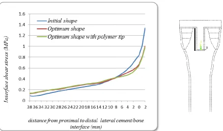
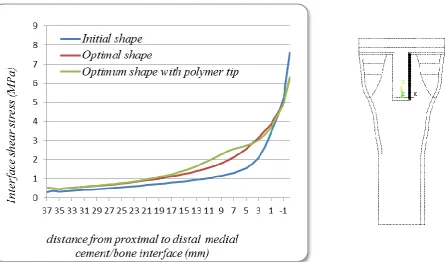
diaphyseal bone at cement / bone interface was illustrated in Fig. 13 and Fig. 14, respectively. It was found that the stresses increased gradually to reach its maximum value at the stem tip. The interface shear stress using the optimal shape was decreased by 25% and 3% for the lateral and medial interfaces, respectively. However the interface shear stress using the optimal shape with polymer tip was decreased by 26% and 2% for the lateral and medial interfaces respectively compared to the initial stem shape.
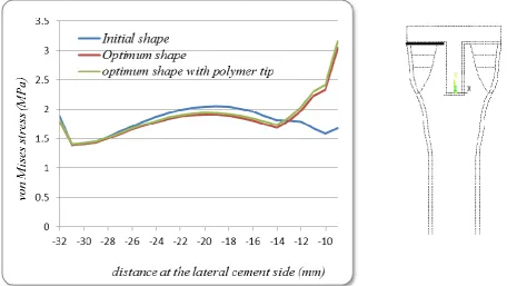
von Mises stress in the lateral and medial cement at cement / bone interface was presented in Fig. 15 and Fig. 16, respectively. It was found that the stresses were reduced along cement / bone interface at all regions except the region of contact between diaphyseal bone with cement. This increase in the cement stress in this region is due to the increase of the stresses in the cancellous diaphyseal bone to reduce the stress shielding problem at this region. The stress in cement was increased by about 80% laterally for the optimal stem shape compared to initial stem shape. However the stress in cement was increased by about 60% medially for the optimal stem shape compared to initial stem shape. This increase was approximately the same using the optimal shape with polymer tip. This increase in the cement stresses is safe and within acceptable range because the von Mises stress in cement at the lateral and medial interfaces does not exceed 6MPa while the yield strength for PMMA is ranged from 80-120MPa [21, 22] and the ultimate shear strength is between 40-50MPa [23, 24].
interfaces. It is found that the stress in cement was reduced for the optimal shape by 28% laterally compared to the stem initial shape. However, the stress was reduced for the optimal shape with polymer by 30% laterally compared to the stem initial shape. Fig. 18 was illustrated the interface shear stress distribution in cement at cement / bone interface at the lateral side which was represented that the stress is concentrated at the distal stem tip as represented in Fig. 17. Related to Fig. 17, it is found that the stress in cement was reduced for the optimal shape and the optimal shape with polymer tip by 17% medially compared to the stem initial shape. Fig. 19 was illustrated the interface shear stress distribution in cement at cement / bone interface at the medial side which was represented that the stress is concentrated at the distal stem tip as represented in Fig. 17.
In this study, the model has been considered to be a 2D finite element model of the cemented tibia prosthesis. The model did not include some effective elements such as ligaments and muscles. Also, the positions of the components have been considered theoretically and the applied load has been assumed constant. Additionally, the material properties of the cemented tibial prosthesis with linear elastic, isotropic, and heterogeneous bone properties were assumed in this analysis. This simplified model was used before through many researches [3, 14, 17]. These assumptions were made in order to make it possible to find the optimal shape for cemented tibia tray design with minimum man-hours which are needed to develop and create the model. Then the optimal shape can be applied on any real 3D tibia prosthesis model.
4. CONCLUSION
The optimal shape for a cemented tibia in knee replacement is concluded to be a short tapered stem with a small diameter at the distal stem tip increased gradually to reach its maximum value at the proximal stem.
This optimal shape is succeeded to increase von Mises stress at the lateral and medial cancellous bone by 130% and 140%, respectively compared to initial stem shape.
On the other hand the stress concentration in bone at stem tip using the optimal stem shape is reduced by 25% compared to initial shape.
The von Mises stress in cement is reduced by 28% at the lateral side and by 17% at the medial side using the optimal stem shape compared to the initial shape.
It is found that using a polymer stem tip with the optimal shape was increase the stresses in the proximal cancellous bone and it was reduce the stress concentration at the stem tip. However, its improvement in solving the stress shielding proximally and the stress concentration distally does not make a big difference compared to the optimal titanium stem.
REFERENCES
[1] Jr C.A Engh, A.M. Young, Sr C.A. Engh, R.H. Hopper,
"Clinical consequences of stress shielding after porous-coated total hip arthroplasty", Clin Orthop, 417, 157-163, (2003).
[2] A. Completo, F. Fonseca, A. Simões, A. Ramos, C.
Relvas, "A new press-fit stem concept to reduce the risk of end-of-stem pain at revision TKA: A pre-clinical study", The Knee, 19, 537–542, (2012).
[3] D.Y.R. Chong, U. Hansen, A.A. Amis, "The influence
of tibial prosthesis design features on stresses related to aseptic loosening and stress shielding", Journal of Mechanics in Medicine and Biology, 11(1), 55-72, (2011).
[4] H.S. Hedia, N. Fouda, "Improved Stress Shielding on a
Cementless Tibia Tray using Fuctionally Material", Materials Testing, Numerical Simulation, 55 (11-12), 845-851, (2013).
[5] J.S. Arora, "Introduction to Optimum Design", second ed. Elsevier Academic Press, USA, (2004).
[6] A. Completo, P. Talaia, F. Fonseca, J.A. Simoes,
"Relationship of design features of stemmed tibial knee prosthesis with stress shielding and end-of-stem pain", Materials and Design. 30, 1391–1397, (2009).
[7] C. I. Kimpton , A. D. Crocombe, W.N. Bradley, G.
H.O. Brigstocke, "Analysis of Stem Tip Pain in Revision Total Knee Arthroplasty", the Journal of Arthroplasty, 28, 971–977, (2013).
[8] G. Mallesh, S.J. Sanjay, "Finite Element Modeling and Analysis of Prosthetic Knee Joint", International Journal of Emerging Technology and Advanced Engineering. 2(8), 264-269, (2012).
[9] A.G. Au, A.B. Liggins, V. J. Raso, A. Amirfazlia, "A parametric analysis of fixation post shape in tibial knee prostheses", Medical Engineering & Physics, 27, 123– 134, (2005).
[10] J. Dargahi, S. Najarian, S. Amiri, "Optimization of the geometry of total knee implant in the sagittal plane using FEA", Bio-Medical Materials and Engineering, 13, 439–449, (2003).
[11] L. M. Jazrawi, B. Bai, F. J. Kummer, R. Hiebert, S. A.
Stuchin, "The Effect of Stem Modularity and Mode of Fixation on Tibial Component Stability in Revision Total Knee Arthroplasty", the Journal of Arthroplasty, 16(6), 759-767, (2001).
[12] H.S. Hedia, D.C. Barton, J. Fisher and T.T. El-Midany
"A Method for Shape Optimization of a Hip Prosthesis to Maximize the Fatigue Life of the Cement." J. Med. Eng. Phys., 18(8), 647-654, (1996).
[13] H.S. Hedia, D.C. Barton, J. Fisher and A. Ibrahim
"Shape Optimisation of Charnley Prosthesis Based on the Fatigue Notch Factor." J. Bio-Medical Materials and Engineering, 6, 199-217, (1996).
[14] D.A. Saravanos, P.J. Mraz, D.T. Davy, "Shape
optimization of tibial prosthesis components", NASA Contractor Report 191123, April 1993.
[15] J.H. Lonner, M. Klotz, C. Levitz, et al., "Changes in bone density after cemented total knee arthroplasty: influence of stem design", J Arthroplasty, 16, 107, (2001).
[16] T.P. Andriacchi, T.S. Stanwyck and J.O. Galante,
"Knee biomechanics and total knee replacement", J. Arthroplasty, 1, 211–219, (1986).
[17] S. N. Nambu, G. Lewis, "Influences of the temporal nature of the applied load and the tibial baseplate material on the stress distribution in a three-dimensional model of the human knee joint containing a prosthetic replacement", Bio-Medical Materials and Engineering, 14, 203–217, (2004).
[18] R. Huiskes, R. Boeklagen, “Mathematical Shape
Optimization of Hip Prosthesis Design”, J. Biomechanics, 22, 793-804, (1989).
[19] R. Huiskes, ”New Approaches to Cemented
Buchhorn and Hans-Georg Willert, Hogrefe & Huber Pudlishers. Seattle. Tronto, 227-236, (1994).
[20] S. M. Darwish, A. Al-Samhan, "The effect of cement stiffness and tibia tray material on stresses developed in artificial knee", International Journal of Adhesion & Adhesives, 28, 120-125, (2008).
[21] M.C. Lawson, K.C. Hoth, C.A. De Forest, C.N.
Bowman, K.S. Anseth, "Inhibition of staphylococcus
epidermidis biofilms using polymerizable
vancomycin", Clin Orthop Relat Res, 468, 2081-2091, (2010).
[22] J.G.F. Santos Jr., V.J.R.R. Pita, P.A. Melo, M. Nele, J.C. Pinto, "Production of bone cement composites: effect of fillers, co-monomer and particles properties", Brazilian Journal of Chemical Engineering, 28(2) 229-241, (2011).
[23] P.C. Weinrauch, C. Bell, L. Wilson, B. Goss, C.
Lutton, R.W. Crawford, "Shear properties of bilaminar polymethylmethacrylate cement mantles in revision hip joint arthroplasty", The Journal of Arthroplasty, 22(3), 394-403, (2007).
[24] C. Lee, "The mechanical properties of PMMA bone cement", the well-cemented total hip arthroplasty, 3, 60-66, (2005).
Table I
Material property of the tibia and tibial prosthesis
Material Elastic modulus (MPa) Poisson's ratio
Diaphyseal cortical bone 17000 0.3
Metaphyseal cortical bone 5000 0.3
Cancellous epiphyseal bone 400 0.3
Cancellous metaphyseal bone 1 320 0.3
Cancellous metaphyseal bone 2 300 0.3
Cancellous diaphyseal 100 0.3
polymethylemetacrylate (PMMA) 2000 0.23
UHMWPE 1000 0.3
Stem / tray (titanium alloy) 110000 0.33
Fig. 1. (a) The details of the total knee components (b) The total knee components are inserted in a knee joint
Fig. 2. The cross section of a tibial component inserted in the natural knee Tibial component and tibia bone
which will be studied in this analysis
La
ter
al si
de
Media
l si
de
Proximal side
Fig. 3. The finite element mesh with the applied boundary and loading conditions
Fig. 4. The initial shape of cemented tibia tray UHMWPE
insert
C
o
rt
ex
d
ia
p
h
yse
a
l
C
o
rt
ex
m
et
a
p
h
yse
a
l
Ti
b
ia
t
ra
y
Cancellous epiphyseal
Cancellousmetaphyseal 1
Fig. 5. Iteration scheme of the numerical shape optimization procedure. The functions within the dotted boundary are provided by the FEM code.
Load
Material Properties
Boundary Conditions
FEM Mesh
Value Objective Function
Optimal Geometry
Design Criterion
Initial Geometry
Stress / Strain
FEM Mesh Genera
tor
FEM Code
Function Evaluation
Search Procedure
Fig. 6. The optimal shape of cemented tibia tray
Fig. 8. von Mises stress in lateral epiphyseal cancellous bone at cement/bone interface, the bold line on the right figure represents this interface
Fig. 10. von Mises stress in lateral diaphyseal cancellous bone at cement/bone interface, the bold line on the right figure represents this interface
Fig. 12. von Mises stress in bone at the distal tip at cement/bone interface, the bold line on the right figure represents this interface
Fig. 14. Interface shear stress in medial diaphyseal cancellous bone at cement/bone interface, the bold line on the right figure represents this interface
Fig. 16. von Mises stress in medial cement at cement/bone interface, the bold line on the right figure represents this interface
Fig. 18. Interface shear stress in lateral cement at cement/bone interface, the bold line on the right figure represents this interface