[139-144]
INTERNATIONAL JOURNAL OF ENGINEERING SCIENCES
& MANAGEMENT
HAND GESTURE RECOGNITION WITH STATIC AND DYNAMIC FEATURES
1
Rupali Deshmukh,
2Priyanka Patil
1, 2
Assistant Professor, Electronics & Telecommunication Dept.,
Pad. Dr. D.Y.Patil Institute of Engg. & Tech.,Pimpri, Pune ,18
1. INTRODUCTION
1.1 Human computer interface system
Computer is used by many people either at their work or in their spare-time. Special input and output devices have been designed over the years. The purpose of all these things is to improve communication between computers and humans. The two most known devices are the keyboard and mouse . Every new device can be seen as an attempt to make the computer more intelligent and making humans able to perform more complicated communication with the computer. This has been possible due to the result oriented efforts made by computer professionals for creating successful human computer interfaces.
The idea is to make computers understand human language and develop a user friendly human computer interfaces (HCI). Making a computer understand speech, facial expressions and human gestures are some steps towards it. Gestures are the non-verbally exchanged information. A person can perform countless gestures at a time. Since human gestures are perceived through vision, it is a subject of great interest for computer vision researchers. The project aims to determine human gestures by creating an HCI. Coding of these gestures into machine language demands a complex programming algorithm.
1.2 Gestures
As per the context of the project, gesture is defined as an expressive movement of body parts which has a particular message, to be communicated precisely between a sender and a receiver. A gesture is scientifically categorized into two distinctive categories: dynamic and static. Gesture recognition is the process of recognizing and interpreting a stream continuous sequential gesture from the given set of input data.
2. LITERATURE SURVEY
2.1 Literature survey:
In [1] an environment was conducted to investigate gesture recognition with human hand manipulating the dataglove. Gesture recognition was investigated with repeated measurements of American sign language signs made by experienced signers.
In [2] the focus is on problem on tracking nonrigid objects in complex scenes, including the case where there are other moving objects present. In that model based method is used in which two dimentional models are extracted from the image data and matched to successive frames of image sequence. The method implemented in this papersuccess fully tracked object through image sequences in which they change overall shape substrancially they move large distances from one frame to next and they may be partially or fully overloaded in successive frames.
In [3] a basis for understanding the hand gesture recognition field by describing the key-hand tracking technologies and applications using glove based input is provided.
In [4] the techniques for computing a prototype trajectory of an ensemble of trajectory for defining configuration states along the prototype and for recognizing gestures from an unsegmented continuous stream of sensor data. The approach is illustrated by application to range of gesture related sensory data, the two dimensional moments of a mouse input device the moment of hand measured by magnetic special position and orientation sensor and lastly the changing eigen vector projection coefficient computed from an image sequence.
3. THEOROTICAL BACKGROUND
3.1 Problem definition
:
Computer vision based hand tracking can be used to interact with computers in new innovative ways. Our task was to extract certain features from the gesture trajectory so as to identify the form of trajectory.
3.2 Problem Motivation:
1. Editing platforms using hand gestures.
2. Implementation of computer mouse using fingers. 3. Gesture identification for behavior recognition.
4. Hand tracking using low-cost webcams find a lot of applications in interactive gaming and applications as hand. 5. Gesture recognition is a current field of research and a lot of work is being done on it.
6. Applications such the photo browsing in an i-phone or other systems using touch-sensitive surfaces can also be implemented using image processing thus giving an alternative to the use of such surfaces.
3.4 Flow of work
The work is divided into mainly three parts
:
3.4.1 Image capture 3.4.2 Pre-processing 3.4.3 Feature extraction
3.4.1 Image capture:
In this first the image is captured by web camera and given for preprocessing. In this project instead of using skin color detection of specific color is used for better results.
3.4.2 Pre-processing
In this process captured image is taken and processing of that image is done. The flow of pre-processing is as follow:
a. Frame extraction b. Gaussian blur c. RGB to HSV model d. Color Thresholding e. COG detection f. Add to feature list
3.4.3 Feature Extraction
a.
Find centre of gravity of full pattern b. Normalize (1 D- Blur filter)c. Scaling d. Features Recognition
a.
Train b. Testing3.5 Gaussian blur
A Gaussian blur is the result of blurring an image by a Gaussian function. It is a widely used effect in graphics software, typically to reduce image noise and reduce detail. The visual effect of this blurring technique is a smooth blur resembling that of viewing the image through a translucent screen, distinctly different from the bokeh effect produced by an out-of-focus lens or the shadow of an object under usual illumination. Gaussian smoothing is also used as a pre-processing stage in computer vision algorithms in order to enhance image structures at different scales. Mathematically,
applying a Gaussian blur to an image is the same as convolving the image with a Gaussian function. The Gaussian blur is a type of image-blurring filters that uses a Gaussian function for calculating the transformation to apply to each pixel in the image. The equation of a Gaussian function in one dimension is
22
2 2 2
1
x
e x
G
3.1
in two dimensions, it is the product of two such Gaussians, one in each dimension
22 2
2 2
2 1
,
y x
e y
x G
3.2
where x is the distance from the origin in the horizontal axis, y is the distance from the origin in the vertical axis, and σ is the standard deviation of the Gaussian distribution. When applied in two dimensions, this formula produces a surface whose contours are concentric circles with a Gaussian distribution from the center point. Values from this distribution are used to build a convolution matrix which is applied to the original image. Each pixel's new value is set to a weighted average of that pixel's neighborhood. The original pixel's value receives the heaviest weight and neighboring pixels receive smaller weights as their distance to the original pixel increases. This results in a blur that preserves boundaries and edges better than other, more uniform blurring filters see also scale-space implementation.
3.6 Thresholding
Thresholding is the simplest method of image segmentation. From a grayscale image, Thresholding can be used to create binary images
.
3.6.1 Method
During the thresholding process, individual pixels in an image are marked as "object" pixels if their value is greater than some threshold value and as "background" pixels otherwise. This convention is known as threshold above. Variants include threshold below, which is opposite of threshold above; threshold inside, where a pixel is labeled "object" if its value is between two thresholds; and threshold outside, which is the opposite of threshold inside. Typically, an object pixel is given a value of “1” while a background pixel is given a value of “0.” Finally, a binary image is created by coloring each pixel white or black, depending on a pixel's labels.
3.6.2 Threshold selection
[139-144] the rationale being that if the object pixels are brighter than the background, they should also be brighter than the average. One method that is relatively simple, does not require much specific knowledge of the image, and is robust against image noise, is the following iterative method:
1. An initial threshold (T) is chosen, this can be done randomly or according to any other method desired. 2. The image is segmented into object and background
pixels as described above, creating two sets: 3. G1 = {f(x,y):f(x,y)>T} (object pixels)
4. G2 = {f(x,y):f(x,y) T} (background pixels) (note, f(x,y) is the value of the pixel located in the x column, y row)
5. The average of each set is computed
6. X1 = average value of G1 and X2= average value of G2
7. A new threshold is created that is the average of X1 and X2
8. T’ = ( X1+ X2)/2
9. Go back to step two, now using the new threshold computed in step four, keep repeating until the new threshold matches the one before it (i.e. until convergence has been reached).
This iterative algorithm is a special one-dimensional case of the k-means clustering algorithm, which has been proven to converge at a local minimum—meaning that a different initial threshold may give a different final result.
Determination of centroid of hand image
After determining binary alpha plane corresponding to each VOP, moments are used to find the center of the hand. The0th and the 1st moments are defined as:
x y
y
x
I
M
00(
,
)
…………..3.3
x y
y
x
xI
M
10(
,
)
…………3.4
x y
y
x
yI
M
01(
,
)
…………3.5
Subsequently, the centroid is calculated as
00 10
M
M
x
c
and
00 01
M
M
y
c
…………3.6
In the above equations, I(x, y) is the pixel value at the position(x, y) of the image. Since the background pixels are assigned“0”, the centroid of
the hand in a frame is also
the centroid of
the total frame. Therefore, in moment calculation, we may either take the summation over all pixels in the frame or over only the hand pixels.Estimation of centroids of motion trajectory
Centroid is calculated both by moment equations as well as by motion vector, where centroid Ci is obtained by translating Ci−1 by the respective motion vector. The final centroid is taken as the average of these two. This is to nullify the effect of slight shape changes in successive VOPs.
Bilinear interpolation
In computer vision and image processing, bilinear interpolation is one of the basic resampling techniques. In texture mapping, it is also known as bilinear filtering or bilinear texture mapping, and it can be used to produce a reasonably realistic image. An algorithm is used to map a screen pixel location to a corresponding point on the texture map. A weighted average of the attributes (color, alpha, etc.) of the four surrounding pixel is computed and applied to the screen pixel. This process is repeated for each pixel forming the object being textured.
When an image needs to be scaled up, each pixel of the original image needs to be moved in a certain direction based on the scale constant. However, when scaling up an image by a non-integral scale factor, there are pixels (i.e., holes) that are not assigned appropriate pixel values. In this case, those holes should be assigned appropriate RGB or grayscale values so that the output image does not have non-valued pixels.
4 FEATURE EXTRACTION
4.1 Static features
4.1.1 Key trajectory point selection
The basic principle of key point selection is merging of adjacent approximation interval of the estimated trajectory, until the interpolation error exceeds a predefined threshold. Key points are defined by their coordinates in 2D space and time, i.e., (x, y, t). These key points best represent the prominent locations of the hand in the gesture trajectory. The total number of key points can be chosen by the user so that the global precision and compactness required by the application is met, and variable time intervals between key points can be chosen to match the local trajectory’s smoothness. Ideal key points in the ‘circle’ and ‘square’ representing gesture.
4.1.2 Trajectory length calculation:
2
1 2 1 2
1
)
(
)
}
{(
x
ix
iy
iy
iD
……….4.1
.where the summation in runs from i = 0 to N − 1.
4.1.3 Location feature extraction:
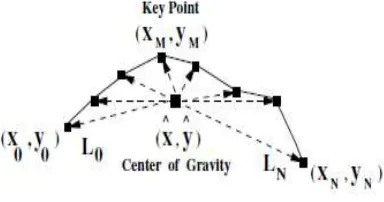
The location feature is the measure of the distance between the center of gravity and the selected key points in a gesture trajectory, as depicted in Fig.4.1
.
Fig 4.1 Extraction of location feature
The location of a gesture trajectory cannot be solely determined from the origin/start point, since for a particular gesture there is always spatial variation in the gesture start point. This is solved by using the gesture center of gravity for calculation of locations of the selected key points on the gesture trajectory.
The center of gravity of a gesture trajectory is calculated as,
Ni i
x
N
x
0
^
1
And
Ni i
y
N
y
0
^
1
……….4.2
and the location of different key points from the center of gravity is calculated as
2 ^ 2
^
)
(
)
(
x
x
y
y
L
i
i
i
…………4.3
where (xi, yi) is the ith key point. The average positional distance of all the key points from the center of gravity, given as
Ni i
avg
L
N
L
0
1
1
…………4.4
Lavg is our proposed location feature that is related to the overall gesture size
4.2. Dynamic features
Motion features are computed from the spatial positions of hand in the gesture trajectory and the time interval between two prominent hand positions as follow.
4.2.1 Velocity feature
In some critical situations, velocity feature plays a decisive role during gesture recognition phase. It is based on an important observation that each gesture is made at different speeds, as depicted in Fig. For a circle re presenting gesture, hand velocity is more or less constant throughout the gesture, whereas in square gesture, velocity of the hand decreases at the corner points of the square and/or if hand pauses at the corner points velocity drops to zero.
999Fig.4.2. Ideal velocity plot of (a) Circle and (b) Square representing gestures
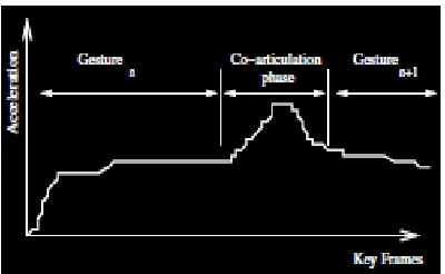
4.2.2 Acceleration feature
[139-144]
Gesture
Fig.4.3 Ideal acceleration plot for gestures connected sequentially5. EXPERIMENTAL RESULTS
5.1 Thresholding of imagesFig 5.1 : Thresholding of symbol‘ square’
5.2 Symbol Packs of Different shape
Fig 5.2: Symbol pack for ‘square’
Fig 5.3: Symbol pack for ‘circle’
6. CONCLUSION
6.1 ConclusionTrajectory guided recognition will be efficient method in hand gesture recognition. In this method the features used are both static as well as dynamic. Hence as compared to other methods it will give the more accurate results. As the color detection is used instead of skin color detection drawbacks or disadvantages of skin color detection like change in intensity are overcame.
6.2 Future work
Area of Hand gesture based computer human interaction is very vast. This project extracts certain features like length, location, velocity, acceleration which will give important information for gesture classification stage. Hand gesture recognition can be successfully used for applications like robot control, television control
.
REFERENCES
[1] D.L. Quam, “Gesture recognition with a data glove,” Proc. IEEE Conf. National Aerospace and Electronics, vol. 2, pp. 755–760, 1990.
[2] D. P. Huttenlocher, J.J. Noh, and W.J. Rucklidge, “ Tracking non-rigid objects in complex scene”, Proc. Fourth International Conference of Computer Vision, pp. 93–101, 1993.
[3] D.J. Sturman, and D. Zeltzer, “A survey of glove-based input,” IEEE Computer Graphics and Applications, vol. 14, pp. 30–39, 1994.
[4] Aaron Bobik, Andrew D Wilson,” A state based technique for summarisation and recognition of hand gestures” IEEE,vol 13,pp 383-388,1995.
[5] V.I. Pavlovic, R. Sharma, T.S Huang, “Visual interpretation of hand gestures for human-computer interaction: a review”, IEEE Pattern Analysis and Machine Intelligence, 19(7): 677 – 695, 1997 .
[7] Ho-Sub Yoon, Jung Soh, Younglae J. Bae, Hyun Seung Yang” Hand gesture recognition using combined features of location, angle and velocity”, Pattern Recognition Society,2001.
[8] L. Bretzner, I. Laptev, and T. Lindberg, "Hand Gesture Recognition using Multi-Scale Color Features, Hierarchical Models and Particle Filtering", IEEE International Conf. on Automatic
[9] William T. Freeman, Craig D. Weissman,”Television Control by Hand Gestures”, IEEE Intl. Wkshp. on Automatic Face and Gesture Recognition, Zurich, June, 1995
[10] M.K. Bhuyan, D. Ghosh, and P.K. Bora, “ Finite state representation of hand gestures using key video object plane”, Proc. IEEE Region 10 -Asia-Pacific Conf. (TENCON), , pp. 21–24, 2004.
[11] M.H. Yang, N. Ahuja, and M. Tabb, “Extraction of 2D motion trajectories and its application to hand gesture recognition,”IEEE Trans. Pattern Analysis and Machine Intelligence, vol. 24, no. 8, pp. 1061–1074, 2002.
[12] M.K. Bhuyan, D. Ghosh and P.K. Bora,”Feature Extraction from 2D Gesture Trajectory in Dynamic Hand Gesture Recognition”, IEEE, 2006 [13] M.K. Bhuyan, D. Ghosh, P.K. Bora, “Trajectory guided recognition of hand gestures for human computer interface,” Proc. 2nd Indian International Journal
[14] Sushmita Mitra, Tinku Acharya,”Gesture Recognition: A Survey”, IEEE transactions on systems, man, and cybernetics—part c: applications and reviews, vol. 37, no. 3, may 2007.
[15] Luo Dan and Jun Ohya,”Hand-gesture Extraction and Recognition from the Video Sequence Acquired by a Dynamic Camera Using Condensation Algorithm”, Intelligent Robots and Computer Vision.
[16] Daniel R. Schlegel, Albert Y. C. Chen, Caiming Xiong, Jeffrey A. Delmerico, Jason J. Corso,” AirTouch: InteractingWith Computer Systems At A Distance” IEEE Trans 2010.