Implementation of Two Parallel FIR Filter
Structure using LUT less DA
Vamshi Krishna Alle Mrs. E. Chitra
M. Tech Student Assistant Professor (Sr. G)
Department of VLSI Design Department of Electronics and Communication/VLSI Design
SRM University, Chennai, India SRM University, Chennai, India
Abstract
This paper describes the implementation of two parallel FIR filter based on traditional method costs considerable hardware area and power. The FIR filters mainly contain the delay elements, adders and multipliers. The usage of multipliers in the filter structure leads to two drawbacks; they are (i) increase in area and (ii) increase in delay which may results ultimately in low speed and performance. A new design and implementation of two parallel FIR filter structure using LUT (Look Up Table) less Distributed Arithmetic (DA) is proposed in this paper which are beneficial to symmetric coefficients reducing half of the multipliers in sub filter blocks of two parallel FIR filter. The LUT less method is used to decrease the amount of required memory units in the two parallel filter structures. In proposed structure, the multipliers are replaced with shifters and adders so that adders weight less than multipliers in terms of silicon area. The overweigh from the additional adders in preprocessing and post processing blocks stay fixed along with the filter length and they doesn’t increase with tap length, this is the key merit of FIR filter architectures. Overall, the synthesis result shows that the proposed two parallel FIR structure can save more than 50 percent of significant area and power of circuit scale and can be applied to different types of filters with different coefficients for its flexibility and high reliability.
Keywords: Two parallel FIR filter, LUT less Distributed arithmetic (DA), Finite Impulse Response (FIR), Symmetric coefficients
________________________________________________________________________________________________________
I.
I
NTRODUCTIONDue to increase in multimedia applications, the demand for low power and high performance Digital Signal Processing (DSP) is getting higher. Finite Impulse Response (FIR) and Infinite Impulse Response (IIR) digital filters are two kinds of filters used in DSP applications. Digital filters are used in variety of applications varying from wireless communications to audio, video, image processing and digital communication systems. Filters are the basic components of all telecommunication and signal processing units.
Finite Impulse Response (FIR) digital filters are the most fundamental devices performed in DSP systems. Parallel Architecture increase the sampling rate by considering multiple inputs required can be processed in parallel and produce multiple outputs at the same time, this increases the area but this technique can reduce the power consumption by lowering the supply voltage. The area complexity in hardware implementation of FIR filter is one of the major problem. However, an L level parallel processing can increase the number of computations i.e., multipliers and adders by L times.
In some applications, FIR filter functions as high frequencies and low power circuit with high throughput. Moreover, two techniques are used in DSP applications, they are parallel and pipeline processing. In parallel processing technique, multiple inputs are considered and produce multiple outputs at the same time but this increases the area. The area reduction techniques can be found in [1,2,3]. In pipeline process, the critical path is decreased by interleaving the number of latches along the data path, this increase the system latency and number of latches. However, both techniques can reduce the significant power consumption but the sampling speed does not increase.
The two parallel FIR filter using traditional direct arithmetic costs considerable MAC(multiply and accumulate) blocks of different filter order. The proposed two parallel structure uses LUT less DA which is a different approach for implementing digital filters. The basic idea is to replace all multiplications and additions by a shifter-accumulator. DA relies on the fact that the filter coefficients are known, so multiplying c[n]x[n] becomes a multiplication with a constant. This is an importance difference and a prerequisite for a DA design. This paper provides the principle of LUT less DA and introduced in FIR filter design. Here the bit positions which having binary values are known as prior. Instead of direct multiplication the multiply operations are carried out by a series of shifters and adders. For example if h(k)= 0.1010, then Y=X*h(k), this can be implemented as Y=X>>1+X>>3, where >> denotes a right shift operation. By using this technique the results produce the same output as direct multiplication.
II.
T
WO PARALLEL FIR FILTER STRUCTURESConsider an N-tap FIR filter which can be expressed in time-domain form as: Y(n)=∑c(i)x(n-i), k=0,1,2, …..∞ ……….. (1)
Fig. 1: FIR filter
Where, c(i) = constant or filter coefficient
x(i) = nth point of input sequences is variable y(n) = output system response
Traditional Two Parallel FIR Filter Structure: A
The traditional two parallel FIR filter structure is shown as,
Fig. 2: Traditional Two Parallel FIR Filter
The output response is given as, Y0 = X0 H0 + z-2X1H1
Y1 = (H0 + H1) (X0 + X1) – H0X0 – H1X1 ……..(2)
The hardware implementation of equation (2) requires three subfilter blocks of length N/2 (where N is the number of taps) with one preprocessing and three postprocessing adders, with totally 3N/2= 1.5N multiplication and 3(N/2-1)+4= 1.5N+4 additions. The traditional two parallel FIR filter structure is implemented by using direct multiplication with a tap length of 24 and the simulation results are shown.
Modified Two Parallel FIR Filter Structure: B
The traditional two parallel FIR filter structure is modified such that it earns more subfilter blocks with symmetric coefficients so that the implementation hardware area is reduced and is shown as,
Fig. 3: Modified Two Parallel FIR Filter
The output response is given as,
The number of required multiplications in the single subfilter block can be decreased by using modified structure. Therefore, the modified structure will reduce approximately one fourth over the traditional filter structure, which results in lowering of hardware cost.
The hardware implementation of equation (3) requires three subfilter blocks of length N/2 with two preprocessing adders and four postprocessing adders. In modified structure the number of adders in preprocessing and postprocessing stage has been increased but it contains two subfilter blocks with symmetric coefficients which results in large number of reduced multipliers, but the traditional structure has only one subfilter block with symmetry of coefficients. The modified two parallel FIR filter structure is implemented by using direct multiplication with a tap length of 24 and the simulation results are shown.
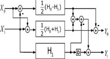
Proposed Two Parallel FIR Filter Structure: C
To use the symmetry of coefficients in FIR filters the proposed structure of two parallel FIR filter is implemented by using LUT less DA, such that it can earn many subfilters blocks with symmetric coefficients which leads to reducing half of multiplications in subfilter that can be reused for multiplications of whole taps. Hence for a L parallel, N tap FIR filter the total amount of saved multipliers will be half the total multipliers i.e., N/2L.
The proposed two parallel FIR filter structure using LUT less DA is obtained by considering modified two parallel FIR filter structure.
Fig. 4: Proposed Two Parallel FIR Filter using LUT less DA
The output response can be written as,
Y0={1/2[(H0+H1)(X0+X1)+(H0-H1)(X0-X1)]-H1X1}+Z-2 H1X1 Y1={1/2[(H0+H1)(X0+X1)-(H0-H1)(X0-X1)]. ..(4)
The proposed structure has three subfilter blocks in which two subfilter blocks contains symmetric coefficients. The DA with LUT less technique is applied to the proposed two parallel (L=2) FIR filter in fig.4 with a tap length of 24 and the simulation results are shown.
III.
24
TAP FIR FILTER DESIGNTo design power and area efficient two parallel FIR filter, consider the filter coefficients which are generated from MATLAB using FDA tool by specifying the type of filter with desired frequencies and different filter order.
The design indexes of the FIR filter is given as a transposed direct-form low pass filter with sampling frequency Fs: 48KHz, pass-band frequency Fpass: 960Hz, stop band frequency Fstop: 1200Hz, filter order: 24, input data width:8, output data width:24. The set of symmetric coefficients are represented as,
{h(0),h(1),h(2),h(3),h(4),h(5),h(6),h(7),h(8),h(9)………..h(22),h(23)}.
where h(0)=h(23), h(1)=h(22), h(2)=h(21), h(3)=h(20), ……,.h(11)=h(12), applying to proposed two parallel FIR filter structure, the top two subfilter blocks will be as
H0 ±H1 ={h(0)±h(1), h(2)±h(3), h(4)±h(5), h(6)±h(7),….., h(20)±h(21), h(22)±h(23) } Where
h(0) ± h(1) = ±(h(22) ± h(23)) h(2) ± h(3) = ±(h(20) ± h(21)) h(4) ± h(5) = ±(h(18) ± h(19))…(5)
Table – 1:
h(6)= h(17)= 0.375420 h(7)= h(16)= 0.038718 h(8)= h(15)= 0.039669 h(9)= h(14)= 0.404318 h(10)= h(13)= 0.40799 h(11)= h(12)= 0.04135
The filter coefficients are quantized by using Maximum Absolute Difference (MAD) algorithm. The subfilter block with half the amount of multipliers required can be realized is shown in figure,
Fig. 5: Sub filter Block Implementation with Symmetric Coefficients
Partition the coefficients according to the sub filter requirement such that two parallel FIR filter structure consider only N/2 coefficients in each sub filter. Therefore, for a 24-tap it takes 12 coefficients in each sub filter block. H0 takes even coefficients and H1 considers odd coefficients. Each outputs of multiplier respond to two taps.
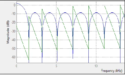
The frequency and phase response of the low pass filter with filter order 24 is shown in figure.
Fig. 6: Frequency and Phase Response
IV.
R
ESULTSThe simulation results are carried out in ModelSim altera 6.4a and area, power constraints are synthesized by using Cadence (RTL Complier) tool.
Traditional two parallel FIR filter using direct multiplication is shown as,
Modified two parallel FIR filter using direct multiplication is shown as,
Fig. 8: Simulation of Modified Two Parallel FIR Filter Using Direct Multiplication
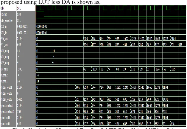
Two parallel FIR filter proposed using LUT less DA is shown as,
Fig. 9: Simulation of Proposed Two Parallel FIR Filter Using LUT less DA
The simulation results shows that, for modified two parallel FIR filter structure using direct multiplication and proposed two parallel FIR filter using LUT less DA gives same output.
The synthesis results of area and power for traditional, modified and proposed structures of two parallel FIR filter is tabulated as,
Table – 2:
Comparison of Area and Power
TWO PARALLEL FIR FILTER AREA
(Cell Area) POWER(nW) TRADITIONAL
STRUCTURE 624673 22371573.6
MODIFIED
STRUCTURE 557546 19224157.8
PROPOSED
STRUCTURE 254729 4622183.15
V.
C
ONCLUSIONThis paper presents the design and implementation of two parallel FIR filter structure using LUT less DA. The simulation results of modified two parallel FIR filter using direct multiplication and proposed two parallel FIR filter using LUT less DA gives same output. Since multipliers consume more area and power, the proposed two parallel FIR filter structure can lead to more than 50 percent reduction in area and power by replacing the multipliers with significant amount of adders and shifters.
R
EFERENCES[1] D. A. Parker and K. K. Parhi, Low-area/power parallel FIR digital filter implementations," J. VLSI Signal Process. Syst., vol. 17, no. 1, pp. 75-92, 1997.
[2] J. G. Chung and K. K. Parhi, Frequency-spectrum-based low-area low-power parallel FIR filter design," EURASIP J. Appl. Signal Process., vol. 2002, no. 9, pp. 444-453, 2002.
[3] K. K. Parhi, VLSI Digital Signal Processing Systems: Design and Implementation. New York: Wiley, 1999.
[4] C. Cheng and K. K. Parhi, \Hardware efficient fast parallel FIR filter structures based on iterated short convolution," IEEE Trans. Circuits Syst. I, Reg. Papers, vol. 51, no. 8, pp. 1492-1500, Aug. 2004.
[5] W. Sen, T. Bin, Z. jun, “Distributed Arithmetic for FIR filter Design on FPGA“ International Conference on Communications, Circuits and Systems, October 2007, pp. 620-623.
[6] N. S. Pal, H.P. Singh, P. I. Sarin, S. Singh, ”Implementation of High Speed FIR Filter using Serial and Parallel Distributed Arithmetic Algorithm,” International Journal of Computer Applications, July 2011 vol. 25, no. 7, pp. 26-32.
[7] He Zhiqiang, Zhang Jingzhi, Zeng wenxian, “Design and Implementation of a Band-pass FIR filter based on FPGA in Multi-channel Data Acquisition System” ICEMI, 2011.
[8] Krishnapriya P.N, Arathy Iyer, “Power and area efficient implementation of parallel FIR filters using FFAs and DA”, IJAREEIE, vol.2, 2013. [9] Heejong Yoo, David V.Anderson, “Hardware-Efficient Distributed Arithmetic Architecture for Higher Order Filters”, IEEE International Conference
on Acoustics, Speech and signal Processing, Vol.5, pp.125-128, March 2005.