e-ISSN: 2250-3021, p-ISSN: 2278-8719 Vol. 3, Issue 1 (Jan. 2013), ||V4|| PP 01-06
Dijkstra Algorithm for Feeder Routing of Radial Distribution
System
Priya Jha, Mr. S. Vidyasagar
PG Student SRM University Chennai, India. Assistant Professor SRM University Chennai, India.Abstract: This paper proposes the application of Dijkstra algorithm for feeder routing of radial distribution system. A complete network of available routes is considered and the optimization goal is to find the routes that provide the minimal total annual cost, which is obtained by the proposed algorithm. Distribution system planning mainly concentrates upon minimising the total annual cost, which is the summation of recovery cost, energy loss cost and undelivered energy loss cost taking in account all the constraints. The feasibility of proposed algorithm is applied on 25 nodes distribution network.
Keyword: Dijkrsta Algorithm, feeder routing, distribution system planning, power flow.
I. INTRODUCTION
Distribution system planning is important to ensure that the growing need of electricity is satisfied by the distributors. Planning starts at customer level, distribution system directly connected to customer any failure in the system would affect the customers. Therefore proper planning of the distribution system is very important for continuity of power. Distribution System Planning (DSP) involves optimal selection of feeder routes, number of feeder, substation size and location [1]. In this work selection of optimal feeder routes is obtained by the proposed method. Several optimization techniques have been implemented to solve the problem of feeder routing. In the past mathematical approach were applied such as branch and bound method for the optimisation of distribution system [2], mixed integer programming [3] applied to the distribution system problem was found feasible, [4] solved the optimal feeder routing using dynamic programming and geographical information systems GIS facilities, which is effective. Another tool to achieve the optimisation goal is ant colon y system algorithm (ACS) [5]. This methodology is meta-heuristic in nature and is very flexible, robust in minimising the investment cost. The reduction in the cost during the planning of distribution system, meeting the constraints is obtained by branch exchange method [6]. The effectiveness of Genetic Algorithm [7-9] is seen in the designing of the distribution system by reducing the solution time. Simulated annealing [10] is also proven to be feasible in planning of the distribution network. In this method the minimum cost solution is obtained by steepest descent approach, further the obtained solution is modified by simulated annealing. This method is faster, taking less consumption time.
In this paper Dijkstra algorithm is the solution strategy for the optimal feeder routes in the planning of the radial distribution system. Dijkstra algorithm is shortest route algorithm [11] that considers the determination of the minimum cost (distance) from an origin to a destination through some connecting graph, used in designing the distribution network. Even in the expansion of the feeders at least cost [12] the proposed algorithm is found feasible. The efficiency of the algorithm is proven in power system restoration [13]. The faulty section is isolated by the proposed algorithm and the supply is restored in the system. The Dijkstra's method is superior because it depends more on the number of arcs than nodes. The proposed algorithm works on directed weighted graph and the edges should be non- negative. The optimal routes are obtained, further to minimise the total cost, current and voltage values are needed. For this load flow analysis is solved [14-15]. The following sections describe the problem statement, details on the proposed algorithm, load flow algorithm to obtain the current and voltage for further proceeding in the optimisation, results obtained by the algorithm used and the conclusion of the work done.
II. PROBLEM FORMULATION
The total annual cost of the distribution system planning is the summation of the fixed cost, energy cost and interruption cost. It is expressed as
C = Cf+ Cl+ Ci
where
Cf is fixed yearly cost
Cl is energy loss cost
The constraints to be satisfied:
i. Capacity constraint P ≤ U U is the vector of capacity limits. ii. The flow in the network model is radial.
iii. The voltage at demand nodes at any time should be within specified limits.
The fixed yearly cost recovery is the capital recovery cost which is represented as Cf = g ∑ Ck
kЄM
Where Ck is the cost of branch k of the main feeder and g is the yearly recovery rate of fixed cost. Cost
of the branch indicates both the line and substation cost. M is the set of all possible branches in a particular radial path. The power loss in distribution system varies with various factors such as level of losses through transmission and distribution lines, transformer, capacitor etc. Power loss can be divided into real and reactive power. The real power is due to the resistance of the lines. The real power loss draws more attention as it reduces the efficiency of transmitting energy to the customers. The cost of energy losses „Cl‟ may be represented
as
Cl = 8760 β p ∑ (Ik)² rk
kЄM β= 0.15 α +0.85 α²
Where p cost per unit of energy lost, β loss factor, rk branch resistance, Ik branch current at peak load and α load
factor.
In the radial networks, there is no alternative supply route and the outage of a branch interrupts the delivery to all the consumers supplied through this branch. Hence, the cost of outage can be calculated using the following expression
Ci= Ci α d∑ λk∛Ur Ik
kЄM
Where Ci cost per unit of energy not delivered, α load factor, d repair duration, λk branch failure rate, Ur network
rated voltage and Ik branch current at peak load.
III. PROPOSED ALGORITHM
The direct solution technique is basically based on searching the optimum path for a node among all the possible paths. Starting from a substation there may be many possible radial paths to reach a node. Then the minimum cost path among all the radial paths for feeding a particular node will be the optimum path for the node. For this Dijkstra Algorithm is used. This algorithm solves as a shortest-route problem that considers the determination of the minimum cost (distance) from an origin to a destination through some connecting graph. After tracing of nodes, load flow is applied to find the current to calculate the energy loss and interruption loss. Henceforth the optimal route is formed by the proposed algorithm.
3.1 DIJKSTRA ALGORITHM
There are several algorithms like Dijkstra‟s algorithm which is a single source- single destination shortest path algorithm, Bellman-Ford algorithm aimed to solve single source shortest path algorithm with negative weights, A* search algorithm solves single pair shortest path problems using heuristics, Floyd Warshall algorithm and Johnson‟s algorithm find all-pairs shortest path. For the work, Dijkstra Algorithm is found suitable. Dijkstra's algorithm is a graph search algorithm used for finding the shortest path from a given node to all the other nodes in the network the criteria for the search, here is the length between two nodes.
The radial distribution system is always a directed path, where power is directed from a substation to the load nodes. A directed graph with ordered pair D= (V, A), where V is a set of vertices or nodes and A is a set of arcs, directed edges or arcs. Dijkstra algorithm being single source shortest path is apt for radial distribution system which has single source, which is the substation from where several paths or feeders are radiated out to the load nodes at certain distance, which is the weight for the algorithm. For the Dijkstra‟s algorithm to work it should be directed- weighted graph and the edges should be non-negative. Each Each arc (i, j) has a positive cost cij associated with it. If there is no arc between nodes i and node k then the distance between them is infinite. This algorithm assigns every node a label: permanent or temporary. Initially all the node except the source node is assigned as temporary label. The nodes which are not linked with the source are given infinity temporary label. Once it is decided that the particular node belongs to minimal path its label becomes permanent.
1. Start with the source node: the root of the tree; which is the substation in this work. 2. Assign a cost of 0 to this node and make it the first permanent node.
3. Examine each neighbour node of the node that was the last permanent node. 4. Assign a cumulative cost to each node and make it tentative.
5. Among the list of tentative nodes
a. Find the node with the smallest cumulative cost and mark it as permanent. A permanent node will not be checked ever again, its cost recorded now is final.
b. If a node can be reached from more than one direction, select the direction with the shortest cumulative cost.
6. Repeat steps 3 to 5 until every node becomes permanent.
IV. LOAD FLOW
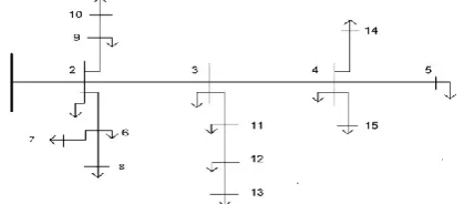
The flow of active, reactive power is known as load flow. Power flow analysis is used to determine the steady state operating condition of the system. The goal of the distribution system power flow function is to study the distribution networks under various loading conditions and configurations. Provided with bus voltage magnitudes and phase angles output from the power flow function, one can derive more information for the distribution network, including real and reactive power flow in each line, line section power loss, and the total real and reactive power at each bus. Radial Distribution Systems (RDS) require special load flow methods to solve power flow equations owing to their high R/X ratio. Hence methods like Newton Raphson cannot be applied. A method name Backward/Forward sweep based on Kirchhoff‟s current law (KCL) and Kirchhoff‟s voltage law (KVL) for evaluating the node currents and voltages iteratively is applied for figure 1. In this approach, computation of branch current depends only on the current injected at the neighbouring node and the current in the adjacent branch. This approach starts from the end nodes and moves towards the root node during branch current computation. The node voltage evaluation begins from the root node and moves towards the nodes located at the far end of the main lines that is to the end nodes. This method is also known as ladder iterative method. It can be classified as:
4.1. Backward Sweep Method 4.2. Forward Sweep Method
Figure 1. Radial distribution networks for 15 nodes
The calculation is done as follows:
4.1 FORWARD SWEEP:
1. Assume rated voltage Vrated at the end node voltages (V 5,V 7, V 8, V10, V 13, V14, V15) in figure 4.1 2. Start with the node 14 and compute the node current I 5 = (S5/V5)*
3. Apply the Kirchhoff‟s current law to determine the current flowing from node 4 toward node 5:I (4−5) = I5. 4. Compute with this current the voltage V 4 = V5 +Z (4−5)*I (4−5). Node 4 is a junction node. Select node
13 and compute the node current I 13 =(S13/V13)*
5. Apply the Kirchhoff‟s current law to determine the current flowing from node 12 toward node 13 I (12−13) = I13
6. Compute with this current the voltage V 12 = V 13 +Z (12−13)*I (12−13) 7. And in this way the forward sweep is applied and reached till the root node.
8. Using the current I (1−2) compute the voltage V1. At the end of the forward sweep the magnitude of the compute voltage V1 is compared to the magnitude of the rated voltage V rated. Error = (Vrated-V1)
4.2 BACKWARD SWEEP:
1. Start with node 1 and V 1 = V rated.
2. Compute the voltage V 2 = V 1− Z (1−2)*I (1−2). 3. Compute the voltage V 3 = V 2− Z (2−3)*I (2−3).
4. In this way the backward sweep continues till the end node. 5. Compute the voltage V 5 = V 4− Z (4−34)*I (4−24).
After the backward sweep the first iteration is completed. At this point the forward sweep will be repeated, only this time starting with the new voltage at end nodes. These steps will be repeated until the error is less than the specified tolerance. This load flow is thus applied on the test case considered. Henceforth this method is superior in number of iteration, computationally efficient, accuracy is high.
V. V. RESULTS AND DISCUSSION
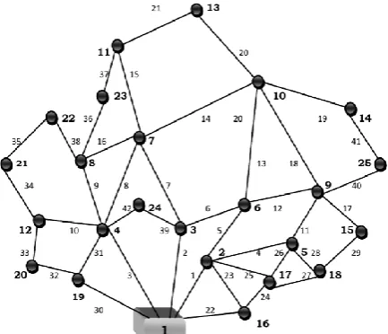
To check the feasibility of the proposed method, it is applied on distribution system. The graph of available network routes for a rural 10 kV network that should be planned is displayed in Fig.5.1. There are 25 load points (transformers 10 kV/0.4 kV) and 42 available route segments/branches for their supply from the source 35 kV/10.5 kV substation at node 1. The edges determine the branch number which is the distance between two nodes that is given in km. The details about the branch number and the length associated with it are given in the Appendix. Total load in the network is 2.55 MVA. The substation cost has been included with the
feeder related cost for every outgoing line emanating from substation is 75k$.
Figure 2. Graph of available supply routes for 25 load nodes distribution network.
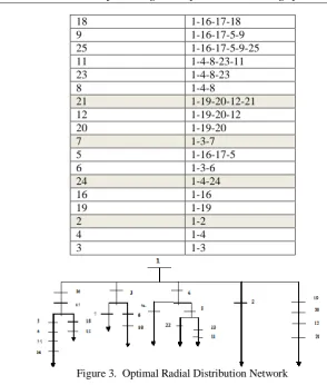
For the graph in Figure 2, Dijkstra algorithm is applied and the optimal path is found. Table I shows the possible paths for energizing all nodes. The shaded region is the optimal feeder routes for the 25 nodes radial distribution system. The optimal routes are 2, 7, 10, 13, 14, 15, 21, 22, and 24. The optimal radial network is shown in Figure 3. The computational time is also drastically reduced as cost evaluations need to be done for fewer paths.
The radial network after applying Dijkstra algorithm is shown in Figure 3. After this the annual cost is calculated. It is summation of fixed yearly recovery cost, energy loss cost and interruption cost. The fixed recovery cost is obtained by summation of total cost of each branch with the rate of recovery. To this the substation cost 75$ is added to the branches. For the outage cost and energy loss cost, current in the system is required, for this, the load flow is applied, explained in section IV.
Table I. Optimal path for 25 nodes Radial Distribution Network Node to be energised Optimal path
15 1-16-17-18-15
14 1-16-17-5-9-25-14
10 1-3-6-10
13 1-4-8-23-11-13
22 1-4-8-22
18 1-16-17-18
9 1-16-17-5-9
25 1-16-17-5-9-25
11 1-4-8-23-11
23 1-4-8-23
8 1-4-8
21 1-19-20-12-21
12 1-19-20-12
20 1-19-20
7 1-3-7
5 1-16-17-5
6 1-3-6
24 1-4-24
16 1-16
19 1-19
2 1-2
4 1-4
3 1-3
Figure 3. Optimal Radial Distribution Network
Table II. Annual Cost in US$ for 25 nodes Radial Distribution Network
Table II shows the total cost of the system considered and the individual cost component for the optimal route obtained by the proposed algorithm. This is the optimal solution for the test case discussed. The proposed technique is developed on MATLAB R2009.
VI. CONCLUSION
In the planning and design model of distribution, the aim to obtain optimal feeder route and to minimize the total annual costs, which includes the capital recovery, energy loss and undelivered energy costs is achieved in this work. The proposed algorithm, Dijkstra Algorithm is proven to be effective for finding the minimum cost route from the substation to the demand side. The computational efficiency and speed of Backward and Forward load flow in distribution system is relatively good compared to the classical methods. Due to the simplicity in the load flow, it is widely used. From the test result on 25 nodes system, it is concluded that the proposed algorithm is effective for obtaining the optimal feeder route and reduces the computational time. Hence the use of Dijkstra algorithm can be applied for distribution system planning.
VII. APPENDIX
Table I. Consumption at Load Points Load point No.
Load, KVA 2 250 3 160 4 100 5 100 6 50 7 100 Load point No.
Load, KVA 8 100 9 250 10 160 11 100 12 160 13 100 Load point No.
Load, KVA 14 100 15 100 16 150 17 80 18 40 19 100 Load point No.
Load, KVA 20 40 21 60 22 40 23 80 24 100 25 30 Optimal solution
Cf Cl Ci Total cost C
REFERENCE
[1] Distribution System Modelling and Analysis, William H. Kersting, New Mexico State University, Las Cruces, New Mexico, p.269-276
[2] T. H. Fawzi, K. F. Ali, and S. M. EI Sobki, “A new planning model for distribution systems,” IEEE Trans. Power App. Syst., vol. PAS-102, no. 9, pp. 3010–3017, Sep. 1983.
[3] R.N. Adams and M.A. Laughton,"Optimal Planning of Power Networks Using Mixed-Integer Programming".Proc. IEE(fLondon),vol.121,pp.139-148, Feb. 1974.
[4] N. G. Boulaxis and M. P. Papadopoulos, “Optimal feeder routing in distribution system planning using dynamic programming technique and GIS facilities,” IEEE Trans. Power Del., vol. 17, no. 1, pp. 242– 247, Jan. 2002.
[5] J. F. Gomez et al., “Ant colony system algorithm for the planning of primary distribution circuits,” IEEE Trans. Power Syst., vol. 19, no. 2, pp. 996–1004, May 2004.
[6] S. Goswami, “Distribution system planning using branch exchange technique,” IEE Trans. Power Syst., vol. 12, no. 2, pp. 718–723, May 1997.
[7] I. J. Ramirez-Rosado and J. L. Bernal-Agustin, “Genetic algorithms applied to the design of large power distribution systems,” IEEE Trans. Power Syst., vol. 13, no. 2, pp. 696–703, May 1998.
[8] Vladimiro Miranda, Rauito, J.V. and Proeup, L.M., “Genetic Algorithms In Optimal Multistage Distribution Network Planning,‟‟ IEEE Trans. on Power Systems, Vol. 9, No. 4, November 1994, pp. 1927- 1933.
[9] Ramirez-Rosado, I.J., and JosB L. Bemal-Agustfn, “Optimization of the Power Distribution Netwoik Design by Applications of Genetic Algorithms,” International Journal of Power and Energy Systems,
Vol. 15, No. 3, 1995, pp. 104-110.
[10] J. M. Nahman and D. M. Peric, “Optimal planning of radial distribution networks by simulated annealing technique,” IEEE Trans. Power Syst., vol. 23, no. 2, pp. 790–795, May 2008.
[11] Y.K. Wong et al., “Effective algorithm for designing power distribution network”, Microprocessor and Microsystems 20,1996, pp. 251-258.
[12] K. Nara, Y. Hayashi, S. Muto, et al., “New feeder determination algorithm by Dijkstra method and tabu search”, ISAP 97,Seoul, 1997, pp. 448–452.
[13] T. D. Sudhakar, N. Shanmuga Vadivoo, S. Mary Raja Slochanal, S. Ravichandran.“Supply Restoration In Distribution Network Using Dijkstra‟s Algorithm”, 2004 lnternational Conference on Power System Technology - POWERCON 2004.
[14] Gary Changa, Shou-Yung Chua,b, Ming-Fong Hsua, Ching-Sheng Chuanga, Hung-Lu Wanga, “An efficient power flow algorithm for weakly meshed distribution systems” Electric Power Systems Research 84 (2012).