http://www.sciencepublishinggroup.com/j/ajae doi: 10.11648/j.ajae.20170402.12
ISSN: 2376-4813 (Print); ISSN: 2376-4821 (Online)
Simulation and Comparative Analysis of Electrodynamic
Railguns for Large Masses Acceleration: Railguns Without
Biasing System
Volodymyr Chumakov, Oleksandr Stolarchuk
Independent Scholars, Kharkiv, Ukraine
Email address:
[email protected] (V. Chumakov)
To cite this article:
Volodymyr Chumakov, Oleksandr Stolarchuk. Simulation and Comparative Analysis of Electrodynamic Railguns for Large Masses Acceleration: Railguns Without Biasing System. American Journal of Aerospace Engineering. Vol. 4, No. 2, 2016, pp. 22-26. doi: 10.11648/j.ajae.20170402.12
Received: December 21, 2016; Accepted: January 12, 2017; Published: November 14, 2017
Abstract:
This paper is the first part of a series of articles devoted to the researching of the principles designing of the railguns to accelerate the macrobodies. Here the results of comparative analysis of the electrodynamic railgun with increased traction for the acceleration of the large mass bodies are shown. Design of accelerators with multi-blade rotor and coaxial accelerator are illustrated and discussed.Keywords: Electrodynamic Railgun, Traction Force, Rotor, Repulsion Force, Torque, Magnetic Field
1. Introduction
Functioning of the electrodynamic railguns (EDRG), both small and large masses are based on the same principles, but the problems to be solved in their design are significantly different [1]. Primarily, the basic difference is an applicative aspect. If the acceleration of low-mass to hypervelocity [2] is mainly scientific application (the studying of extreme states of matter, fundamental research related to the high energy density, the studying of physical processes in the hypersonic acceleration, etc.), the acceleration of large masses to a relatively low velocity has more practical character. Examples of the application EDRG are the following:
trains on magnetic pillows, so-called Maglev trains [3, 4]; alternative to gas-dynamic and jet launch of the manned and unmanned spacecraft to reduce takeoff weight, to provide fuel economy and to increase flight range [5]; the meteorological rockets with the aim of increasing the payload or as an alternative method of delivery weather balloons into the upper atmosphere;
launching of the unmanned aerial vehicles (UAV), which not only increases the range of the UAV, but also provides the opportunity, starting in the absence of a runway[5];
basic system of aircraft-carrier landing complex for
short-cut takeoff aircraft lifting platforms deck home [6, 7].
Author's team has developed a number of large masses EDRG, each of which can be used to solve a given task. To carry out a comparative analysis of different types of EDRG, each of them was designed to developtraction force on the rotor (moving part of the railgun) 1.6 MN. The simulation was performed within one section length of 2000 mm and 500 mm interrails gap. Since the duration of the current supply pulse in the large masses EDRG is the units or part of seconds (depending on the section number in the accelerator), the simulation was carried out in the magnetostatic mode. A comparison was carried out on the current value, required for a given traction force on the rotor.
2. Designing of the Railguns with
Different Rotor Systems
2.1. Railgun with Plane Rotor
Figure 1. Railgun with plane rotor.
Supplying of currents in the EDRG is 105 ÷ 107 A that causes immense forces which seek to expand the current loop, whileelectrical contact of the rotor with the rails is provided on the latest ends of rotor. As the result the deformation of rails and the loss of reliable electrical contact with rotor take place. As it is shown on figure 1 the design of each guide rail pair is represented by a parallel buses, and an electrical contact is provided with the envelopment of rotor ends on the upper and lower sides. When power is applied, the current is divided between the buses into half, and electrodynamic forces, occurring in parallel buses, are seeking to reconcile the bus together, providing a reliable contact with rotor. In the same time the electrodynamic repulsion forces with reverse current in rails in this design are not so critical, because it does not affect the reliability of the contact and can displace only along its upper and lower surfaces.
The plane rotor design ensures both a possibility to move into the small gap tire pair and a sufficiently large cross-sectional plane of the supply current to pass without substantial overheating.
The calculation showed that to providethe traction with rotor of 1.6 MN, and guiding bus pair must be powered by the current of 1.77 MA. At the same time the power buses in a pair attraction with the force per unit length of 2.17 MN/m, and the bus pairs repulsion force per unit length is 0.4 MN/m. The advantage of this design is its simplicity. The EDRG built under the scheme, have been studied well both theoretically and practically [8, 9]. The disadvantages include the need of current source megaampere range and as a result, it led to the rapid wear of the railsdue to ablation and deformation under the influence of the electrodynamic force [10, 11].
2.2. Railgun with Dual Double-Blade Rotor
According to the law of Ampere
F=IB l× (1)
increasing the force exerted on a conductor of length l is achieved either by increasing the current in the conductor, or by increasing the magnetic induction in the loop where currentflows, or by increasing both components simultaneously. In theEDRG with double two-blade rotor, the increasing of traction is ensured by increasing the length of
the conductor at a constant gap between rails. This is achieved by constructive combining of two orthogonally arranged railgun (figure 2). Expression (1) shows that in vector product B×l, the contribution to the increase of F will be given only to the normal component of the magnetic field. In the above construction, the magnetic field created by a pair of rails located in the YZ plane, will have mostly a normal component of the magnetic field in its plane and tangential component in the plane XZ. Then, in the XZ plane can be placed an additional pair of rails with its rotor, for which the normal component of the magnetic field will be created by the same pair. Thus, the idea of creating of the double two-blade rotor EDRG is to constructively combine the two plane railguns, placing them orthogonally to each other. The magnetic field accelerating rotor F is created by a pair of rails located in the plane YZ, and rotor B– in the XZ plane respectively, and the rotors themselves are located on a common axis, summing their traction.
Calculations were made for two variants of the power supply of the railgun. In a first embodiment, the direct current lead is in the YZ plane, and the reverse – in the XZ plane. In the second embodiment, there is a straight line in each plane and theback current conductors.
Figure 2. Railgun with double-blade rotor.
According to the simulation results of the first power supply embodiment, the total traction force of 1.6 MN is achieved at a current of 1.35 MA. At the same time, the attaching force per length unit of the buses in a pair is 1.3 MN/m, and the force of repulsion per length unit of the buses pairs is 0.25 MN/m.
On practice, the magnetic field distribution is much more complicated, and the currents that flow in the YZ plane distort the field in the XZ plane. Thus, the doubling of summary traction by using two rotors is not possible. However, this design provides the adjusted traction by smaller currents in comparison with the railgun on figure 1.
axle connecting the rotors due to the difference in tractive force developed by the rotors F and B, as well as the low efficiency of additional railgun, which, however, can be improved by optimization of design for a specific purpose.
In the second embodiment of the supply circuit, the total traction of 1.6 MN achieves at a current of 1.18 MA. Then therailspair attraction one another with different force per unit length (from 0.6 to 1.35 MN/m), depending on the rotor location. Repulsion force per unit length also depends on the location of the rails pair and ranges from 0.2 to 0.25 MN/m.
Despite the fact that the second embodiment requires lesshigh-current power supply and rotor plates give almost the same contribution to the total traction load (no tensile load onconducting axis), in such case the rotor plates experience significant torque (15.8 kN×m for the rotor F and minus 27.6 kN×m for the rotor B). And although the design allows these mechanical loads, this effect will have a strong negative impact on the resource of railgun acceleration channel, due to uneven wear of the rails pair and quickly decreasing of contact reliability. However, in embodiments with a lower shoulder, this supply circuit may be more preferable. Furthermore, the torque can be used in the design of railgun intended for launching acceleration of projectiles with gyroscopic stabilization position in space. In this case, a railgun accelerating complex can be designed according to the scheme in which all over the channel sections accelerating torque is zero (at this length occurs main acceleration), and the last section imparts rotation of the projectile.
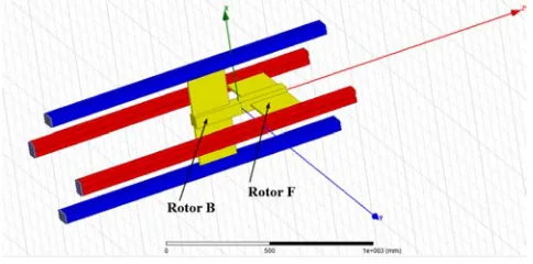
2.3. Railgun with Dual Four-Blade Rotor
This option is a logical continuation of the previous mode of accelerator with dual two-blade rotor, although its construction and operation is more convenient to describe, based on a simple coaxial electrodynamic railgun. In the EDRG with double four-blade rotor the forward and backward current conductors are made in the form of bus pairs, alternately disposed symmetrically about the axis Z (figure 3). Rotors F and B are placed inside coaxially on the traction axis Shaft, turned relative to each other by 450, and the rotor F leans on bus pairs of the straight current conductors, and the rotor B – on reversed. Such a coaxial design eliminates the central coaxial electrode and allows to use the entire internal volume of the acceleration channel.
Figure 3. Railgun with double four-blade rotor.
As in the case of the railgun with double two-blade rotor, the calculations were performed for two current supply options: coaxial and on-paired plane. In the first embodiment, current flows in through the blades of rotor F, and flows out through the blades of rotor B. In the second embodiment, the current, flowing in and out through the opposite blades of the same rotor, is located in the same plane.
According to the simulation results of the first current supply embodiment, the total traction force of 1.6 MN is achieved at a current of 1.17 MA. At the same time the bus pairs attraction force per unit length is 1.0 MN/m, and the repulsion force of the bus pairs per unit length is 0.16 MN/m. In the second current supply embodiment, the total traction force of 1.6 MN is achieved at a current of 0.75 MA. The bus pairs attraction force per unit length is different (0.15 − 0.9 MN/m), depending on the location. The repulsion force of the bus pairs per unit length also depends on the location of the bus pair and ranges from 0.05 to 0.13 MN/m.
The EDRGwith four-blade dual rotor, the rotor plates also have torque when the power is turned on on the second embodiment, (minus 10.2 kN×m for the rotor F and 22.5 kN×m rotor B). In addition, in this design summarizing the axis is subjected to tensile load, which, although is not as great as in the first embodiment of power, but still it is enough to need its account in the calculation of the mechanical strength.
2.4. Coaxial Four-Blade Railgun
From the point of view of electromagnetic compatibility, the coaxial structure is the most preferred, since the electromagnetic field is concentrated mainly within the coaxial conductor. Currently existing coaxial EDRG generally represent two coaxial cylindrical conductors. A significant drawback of this design is the low value of inductance per unit length and the inability to make the acceleration channel length, due to the fact that the center conductor at great length begins to sag under its own weight, and installation of the support struts structurally is impossible because of the inevitability of their intersection with the projectilemotion trajectory.
Figure 4. Coaxial railgun with four-blade rotor.
distributed evenlyaround the central axis Z. These four buses are in contact with the cruciform four-blade rotor in the corner of each of its quadrants. The ends of the rotor blades rest on the grooves of the direct current conducting bus pairs. Thus, the rotor can move freely through the coaxial barrel of any length, with good electrical contact it is ensured by electrodynamic forces of interaction in both forward and backward bus systems.
The calculation showed that for the development of rotor traction of 1.6 MN, directing bus pair must be supplied in the current 0.78 MA. At the same time the bus pairs attraction force per unit length is of 0.46 MN/m, the repulsion force of the bus pairs per unit length is 0.45 MN/m, and the mutual attraction force per unit length of the central coaxial conductor buses is 2.19 MN/m.
The high degree of axial symmetry of the accelerating field, implicit in the principle of building the coaxial systems,
and uniform current distribution in each of the rotor arms, allow to construct reliable railgun with zero torque. At the same time, in this embodiment of railgun, the significant limitation is imposed on using of the internal space of the acceleration channel because of some accommodating components here.
3. Conclusions
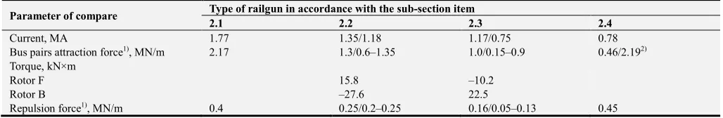
The simulation of railguns of large masses accelerated without further biasing showed the capability of developing a given traction force of 1.6 MN. Estimated value of the current required to operate the EDRG in a given mode, is a parameter by which it is possible to compare the effectiveness of designing. Comparative characteristics of the railguns, the calculation and analysis which were conducted under this section are presented in Table 1.
Table 1. Railgun parameters providing traction force 1.6 MN.
Parameter of compare Type of railgun in accordance with the sub-section item
2.1 2.2 2.3 2.4
Current, МА 1.77 1.35/1.18 1.17/0.75 0.78
Bus pairs attraction force1), MN/m 2.17 1.3/0.6–1.35 1.0/0.15–0.9 0.46/2.192)
Torque, kN×m
Rotor F 15.8 –10.2
Rotor B –27.6 22.5
Repulsion force1), MN/m 0.4 0.25/0.2–0.25 0.16/0.05–0.13 0.45
1)Depending on current supply embodiment. 2)Bus pairs/Bus electrodes of the central conductor
Analysis of the modeling results and studying of the designed railguns characteristics allowed to identify the specifics of each of them and defining its practical application.
Railgun with plane rotor is compact and simple enough to use it in cases where overall dimensions are crucial. That is why, despite the fact that it is free from the acceleration channel structural elements, its direct use is rather difficult tolarge mass acceleration. At the same time, easy access to the rotor allows to provide a constructive possibility of mechanical engagement with the shuttle moving in the guide elements of the accelerator complex. The price for this feature is the maximum supply current, limiting the mobility of the device and making it difficult to some embodiments thereof.
The railguns with double two- and four-blade rotor have the volumetric acceleration, and we can use it both as a whole rotor construction accelerating and for the accelerated body accommodation. Free access to the rotor also allows to use it as an exterior driver for massive bodies as part of the acceleration complex. The presence of significant tensile forces on the traction axis in the first current supply embodiment and twisting forces (due to oppositely directed torques of rotors B and F) for the second variant - is a separate problem that must be solved forthe railgun designing process. Further work to reduce these negative effects will not only simplify the railgun designing, but further reduce the current supply value.
Coaxial railgun with four-blade rotor provides the greatest specific value of traction or a predetermined traction(1.6 MN), out of all the variants shown before, with a minimum value of the current supply. This conclusion is based on a comparative analysis of the coaxial railgun and the railgun with double four-blade rotor. Despite the fact that the first railgun has the active conductor length of interaction with a current much smaller than the second (due to the presence in the latter two rotors and exceptions from this length of the traction axis diameter of the rotor), this mode of the railgun provide the same traction. The consumption current is almost equal to the minimum (Table 1). Although the use of the total acceleration channel volume in the coaxial railgun is difficult due to presence of the structural elements, the profile of its cross section assumes an ergonomic design for a combination of the acceleration rocket complex.
References
[1] V. I. Chumakov, O. V. Stolarchuk, Pulse processes and systems: Manual for laboratory works, Sevastopol, Naval Academy by of P. S. Nakhimov, 2012, 70 p.
[2] Volodymyr Chumakov, OleksandrStolarchuk. Hypersonic Electrodynamic Railguns with Pulse-Dynamic Biasing System. Engineering and Applied Sciences. Vol. 1, No. 3, 2016, pp. 59-65. doi: 10.11648/j.eas.20160103.13.
[4] Hyung-Woo Lee, Ki-Chan Kim, and Ju Lee, Review of Maglev Train Technologies / IEEE Transactions on Magnetics, 2006, V. 42, No. 7, pp. 1917-1925.
[5] J. R. McNab, Launch to Space With an Electromagnetic Railgun, IEEE Transactions on Magnetics, 2003, V. 39, No. 1, pp. 295-304.
[6] http://www.defensemedianetwork.com/stories/emals-successfully-launches-super-hornets/
[7] Volodymyr Chumakov, Oleksandr Stolarchuk, Electrodynamic Launch System Takeoff-Elevating Platforms for Deck-Based Aircraft Carriers Concept Development and Design, to be publishrd.
[8] S. C. Rashleigh, R. A. Marshall, Electromagnetic Acceleration of Macroparticles to a High Velocities, J. Appl. Phys., 1978, V. 49, No. 4, pp. 2540-2542.
[9] K. Thom, J. Norwood, Jr., Theory of an electromagnetic mass accelerator for achieving hypervelocities, NASA Technical Note, D-886, 1961.
[10] G. L. Rolader, K. A. Jamison, R. A. Villeco, Rail Electromagnetics in a Plasma Armature Railgun. J. Appl. Phys. 1991, V. 70, No. 3, pp. 1227-1234.