Development of a Laser Repetition Rate Stabilization System for
an Intense Laser-Compton Scattering
γ
-Ray Source
∗
)
Michiaki MORI, Atsushi KOSUGE, Hajime OKADA, Hiromitsu KIRIYAMA, Yoshihiro OCHI,
Momoko TANAKA, Keisuke NAGASHIMA and Kiminori KONDO
Quantum Beam Science Directorate, Japan Atomic Energy Agency, 8-1 Umemidai, Kizugawa, Kyoto 619-0215, Japan
(Received 19 June 2013/Accepted 8 July 2013)
Repetition rate stabilization of a mode-locked laser for generating intense laser-Compton scatteringγ-rays has been investigated by means of a phase-locked-loop integral circuit and a microcontroller. The stability of the repetition rate has been improved by more than four orders of magnitude for 3000-s operation compared with that at free-run operation.
c
2014 The Japan Society of Plasma Science and Nuclear Fusion Research
Keywords: laser-Compton scattering, gamma ray, mode-locked laser DOI: 10.1585/pfr.9.4404100
1. Introduction
Recently, progress in high-peak-power laser technolo-gies such as chirped-pulse-amplification (CPA) has proven to be attractive for energetic particle generation via laser– matter interaction. A GeV-class electron bunch and a> 40-MeV proton beam have been successfully produced [1, 2] by using strong laser fields (>1018W/cm2) driven by a high-intensity short-pulse laser. In particular, progress has been made in the development of a laser-Comptonγ-ray (LCS-γ) source with a combination of a laser system and a conventional electron accelerator [3–7]. A photon flux of∼105photons/s has been generated with energies of 1– 10 MeV [3]. Here, the total flux of the LCS-γ’s produced using a pulse laser and electron bunch can be obtained from the following equation:
Ftotal= 16
3 NeNLf
r20
w2 0
, (1)
where Ne is the effective number of electrons in an elec-tron bunch,NLis the effective number of photons in a laser pulse, f is the repetition rate of events, r0 is the classi-cal electron radius, andw0is the spot size at a collisional point. In particular,γ-ray beams have been used as a probe to detect isotopes of interest with nuclear resonance flu-orescence (NRF) for industrial applications [8]. Because this technique can be applied to quantitative management of nuclear fuel, it is suitable for nuclear nonproliferation studies. A useful LCS-γsource for the nondestructive as-say of nuclear fuel and minor actinides in spent nuclear fuel [9, 10] must produce a large number ofγ-ray photons (∼1013photons/s). To achieve such intense γ-ray gener-ation, large-current ultra-high-quality short-bunched elec-tron beams are required. Also, >100-W average power author’s e-mail: [email protected]
∗)This article is based on the presentation at the Conference on Laser and Accelerator Neutron Source and Applications (LANSA ’13).
laser pulses with high repetition rate (∼100 MHz) and nar-row bandwidth (<10−3) are required from the laser system before amplification with an enhancement cavity based on a Fabry-Perot interferometer. A fiber-based CPA laser sys-tem can not only provide a beam of high average power and high repetition rate [11] but also operate over a nar-row band by optimizing the laser design [12]. We have developed a fiber-based 100-W-class laser system for the above application [12]. In particular, synchronizing laser pulses to electron bunches is essential to avoid degrada-tion ofγ-ray flux owing to timing mismatch between laser pulses and electron bunches. In this work, microcontroller-assisted stabilization of a repetition rate system for intense LCS-γgeneration was performed. The laser cavity length fluctuation was highly compensated for over a time scale from 1 ms to >3000 s. This system would be useful for synchronizing picosecond laser pulses to picosecond elec-tron bunches.
2. Stabilization of Laser Repetition
Rate
Normally, synchronization between the master fre-quency source and the mode-locked laser repetition rate can be achieved by using an electromechanical control sys-tem [13, 14]. Here, the phase error signal can be detected by a phase comparison between the master frequency and the laser repetition rate signal, frep = c/2L (where cis speed of light and L is cavity length between the end mirrors), which can be obtained by using a photodetec-tor. Moreover, an electromechanical device such as lead zironate titanate (PZT) can be used to convert an electrical signal to a mechanical displacement. Therefore, it is pos-sible to synchronize the master frequency source and the mode-locked laser repetition rate by properly configuring these devices. To compensate for frequency mismatch
be-c
tween the laser repetition rate and the master frequency, a phase-locked loop (PLL) technique can be used. The PLL technique is a control technique, in which an output signal is generated whose phase is related to the phase of an input “master” signal. The PLL technique is widely employed in electronic applications such as radio communications.
Figure 1 shows a typical block diagram of a hetero-dyne PLL: an electronic circuit consisting of a voltage controlled oscillator (VCO), a phase frequency detector (PFD), and a loop filter. This circuit compares the phase of the master signal with the phase of the signal converted from its output oscillator and adjusts the frequency of its oscillator to keep the phases matched. An error signal is obtained at the PFD. The signal from the PFD is used to control the oscillator in a feedback loop. Keeping the in-put and outin-put phase in lock step implies keeping the inin-put and output frequencies in lock step. The duty ratio of the error signal depends on the value of the frequency and/or the phase mismatch. The sharp error signal from the PFD
Fig. 1 Block diagram of a heterodyne PLL.
Fig. 2 Block diagram of a repetition rate stabilization system. Repetition rate stabilities were obtained by using a frequency counter.
is flattened by the loop filter to maintain high stability of the feedback loop. This processed signal is used as a con-trol signal for the VCO. Here, the frequency of the VCO depends on the control voltage. Therefore, the frequency is controlled by the error signal and it is stabilized by re-peating this loop. Because the low-pass filter acts as a loop filter, the low-frequency component is output and the high-frequency component is cut. This cutofffrequency is the loop bandwidth, and it is related to the repetition rate of the stabilization procedure. The mode-locked laser sys-tem, which includes a repetition rate control device such as a PZT actuator, is equivalent to the VCO. Therefore, the control system has very high affinity in the PLL, and the basic design of the repetition rate control of the mode-locked laser system can also be treated as the PLL.
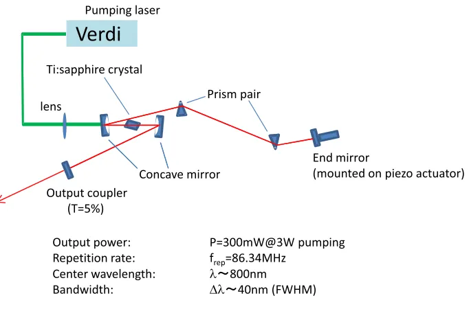
Fig. 3 Configuration of a Ti:sapphire mode-locked laser system. A piezo actuator was placed at an end mirror.
repetition rate stabilization system. We used a Kerr-lens mode-locked Ti:sapphire laser oscillator as a test bench (see Fig. 3). The Ti:sapphire mode-locked laser oscillator provides 40-nm full-width half-maximum (FWHM) band-width with a repetition rate of frep =86.34 MHz. The av-erage output power was 300 mW when the pump power from a green laser was 3 W. The laser pulse output was de-tected by a p-i-n photodiode (PD). This signal was ampli-fied and bandpass filtered (fBPF=83±7 MHz) to detect the laser repetition rate. A double balanced mixer (DBM) was used for frequency conversion. This procedure provides amplification of the phase error sensitivity. Therefore, a low-jitter master oscillator is necessary for frequency conversion. We used a low-jitter frequency synthesizer (SMA100A, Rhode & Schwartz Co., Ltd.) as a primary master oscillator. This master oscillator was assisted by a Rb atomic timebase (FE-5680A, Frequency Electronics Co., Ltd.). The frequency of the master oscillator was set at
fmsr1 =86.40 MHz. Here, the frequency-converted signal (frep-fmsr1 ∼60 kHz) was low-pass filtered (fc = 80 kHz) and digitized. A limit amplifier and Schmidt trigger circuit generated the digitized signal to drive a digital PFD. At the digital PFD, a digitized error signal was compared to a sec-ondary master signal. A frequency-divided signal from the primary master oscillator was used as a secondary master signal source (fmsr2=fmsr1/N=60 kHz,N=1440). Here, the digital PFD outputted a square-shaped phase-difference signal. If used as a control signal for laser cavity directly, this signal would generate jitter or influence the stability of the feedback system (i.e., PLL) by the steepness of the pulse edge. Therefore, the phase-difference signal must be flattened by a low-pass filter. The upper limit of the cut-offfrequency (i.e., loop frequency) can be obtained by the response characteristic of the feedback loop. In our case, the resonance frequency of the piezo actuator dominated
this response characteristic. The piezo actuator has a finite response time that is related to the resonance frequency f0. The resonance frequency f0is described by the following equation:
f0= 1 2π
k M0
, (2)
wherekis the piezo stiffness andM0 is the mass of load. In our case, f0 = 11 kHz is obtained by using a value of k = 50 N/µm for M-5522 (Mess-Tek Co., Ltd.) and
M0 = 0.01 kg for the mass of an end mirror. Then, the highest loop frequency should be set at lower than this resonance frequency. We used a third-order passive low-pass filter with a cutoff frequency of fc = 1.4 kHz. The filtered error signal was provided to a buffer ampli-fier and an assist regulator. We used a microcontroller (MCU) as an assist regulator. A MCU is a small com-puter on a single integrated circuit containing a processor core, memory, and programmable input/output peripherals such as an analog–digital converter and/or digital–analog converter, and a MCU-based assist regulator can provide highly precise controllability and long-term stability. In the developed system, the assist ratio between the assist regulator and the buffered signal was 5:1, corresponding to 900 Hz:170 Hz for the control range of the repetition rate. This processed control signal was provided to a piezo ac-tuator (Mess-Tek M-5522), which was placed at an end mirror of a Ti:sapphire mode-locked laser.
sources [15]. The Allan standard deviation is defined as
σy(τ)=
1
2(yn+1−yn)
2, (3)
whereτ is the observation period andyn is thenth
frac-tional frequency average over the observation timeτ. We took 1000 data points per plot. Comparing between sta-bilization ON and OFF conditions, we see that stabil-ity of the frequency was improved within the loop fre-quency (floop = 1.4 kHz). Here, fluctuation of the laser cavity length can be estimated by using the relationship between cavity length change and repetition rate change:
δL/L = δfrep/frep. For τ = 1 s, variations in the cav-ity length were highly compensated for from 3×10⁻⁸ to 2×10⁻¹², indicating that a 0.1-µm cavity length fluctua-tion was reduced to only 2 picometer by using this system.
Fig. 4 Stability of repetition rate evaluated by the Allan devia-tion.
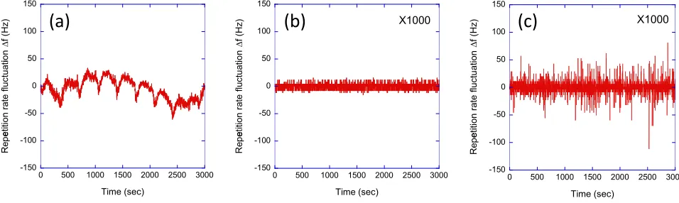
Fig. 5 Long-term stability of the laser repetition rate: (a) stabilization OFF, (b) stabilization ON with assist regulator, and (c) stabilization ON without assist regulator.
We also investigated long-term stability. Figure 5 shows the repetition rate shift from the target frequency (f = 86.34 MHz) as a function of operating time. With stabilization OFF (i.e., free-run condition), the repetition rate fluctuation was estimated to be∼80 Hz for 3000 s. We attribute this fluctuation mainly to background tempera-ture fluctuation and thermal expansion of the baseboard (with 80 Hz being equivalent to a ∼3-µm displacement for a 86.34-MHz repetition rate, which is equivalent to a ∼0.2◦C thermal fluctuation in the steel, which reasonably
matches our room temperature fluctuation). We confirmed that the stability of the repetition rate is improved by more than four order of magnitude. The long-term laser cavity fluctuation is also highly compensated for by installing this stabilization system. In particular, we confirmed improve-ment of long-term repetition rate stability by comparing operation with assist regulation and normal PLL operation (i.e., without an assist regulator). Under normal PLL oper-ation, the original control range of the repetition rate was increased from 170 to 900 Hz by increasing the buffer am-plifier gain and no assist regulator operation. We clearly observed improvement of the feedback loop stability by installation of a MCU-based assist regulator.
4. Summary
Acknowledgments
This work is partly supported by the Ministry of Edu-cation, Culture, Sports, Science and Technology of Japan (Nuclear Security Program).
[1] W.P. Leemanset al., Nature Physics2, 696 (2006). [2] K. Oguraet al., Opt. Lett.37, 2868 (2012).
[3] H. Ohgakiet al., Nucl. Instrum. Methods A455, 54 (2000). [4] S. Kashiwagiet al., J. Appl. Phys.98, 123302 (2005). [5] J. Pruetet al., J. Appl. Phys.99, 123102 (2006).
[6] K. Kawaseet al., Nucl. Instrum. Methods A637, S141 (2011).
[7] F. Albertet al., Phys. Plasmas19, 056701 (2012).
[8] W. Bretozzi and T. Gozani, Nucl. Instrum. Methods B241, 820 (2005).
[9] R. Hajima et al., Nucl. Instrum. Methods A 608, S57 (2009).
[10] T. Hayakawaet al., Nucl. Instrum. Methods A621, 695 (2010).
[11] T. Schreiberet al., Opt. Lett.30, 2754 (2005).
[12] A. Kosugeet al., 60th Spring Meeting of the Japan Society of Applied Physics, Kanagawa, Japan, Mar 2013.
[13] M.J.W. Rodwellet al., IEEE J. Quantum Electron.25, 817 (1989).