© Universiti Tun Hussein Onn Malaysia Publisher’s Office
IJIE
Journal homepage: http://penerbit.uthm.edu.my/ojs/index.php/ijie
The International
Journal of
Integrated
Engineering
Investigation of Multiwavelength Laser Performance
B
ased
on Temperature Variation of PMF and
D
ifferent SOAs
Abdul Hadi Sulaiman
1,2,*, Fairuz Abdullah
2, Aiman Ismail
2, Md Zaini
Jamaludin
2, Nelidya Md Yusoff
3, Mohd Adzir Mahdi
11 Wireless and Photonics Networks Research Center,
Faculty of Engineering, Universiti Putra Malaysia, 43400 Serdang, Selangor, MALAYSIA
2Institute of Power Engineering,
Universiti Tenaga Nasional, Jalan IKRAM-UNITEN, 43000 Kajang, Selangor, MALAYSIA
3Razak Faculty of Technology and Informatics, Universiti Teknologi Malaysia Kuala Lumpur,
Jalan Sultan Yahya Petra, 54100 Kuala Lumpur, MALAYSIA
*Corresponding Author
DOI: https://doi.org/10.30880/ijie.2018.10.07.022
Received 13 July 2018; Accepted 22 November 2018; Available online 30 November 2018
1. Introduction
MWFL has been the main attractions in the application of laser source for wavelength dense multiplexing, optical sensing and many other applications. Several type of comb filters was utilized to generate the multiwavelength laser such as cascaded fiber Bragg gratings [1], Sagnac loop mirror filter [2], Fabry-Perot filter [3], Lyot filter [4–6], Mach Zehnder interferometer [7] and array waveguide grating [8]. Multiwavelength generation based on Lyot filter is an attractive choice for multiple lasing channels due to its advantage of low optical loss and simple design. Some of the MWFL works were based on Lyot filter in conjunction with an erbium-doped fiber amplifier (EDFA) as the gain medium [9,10]. However, due to high mode competition in EDFA, the multiwavelength generation is only limited to a few number of lasing channels. Moreover, the lasing channels is not stable due to homogeneous characteristic in an erbium-doped fiber, unless an additional device is added into the laser cavity to decrease the mode competition, either piezo-electric transducer [11], highly nonlinear fiber [10], nonlinear optical loop mirror [12] or four wave mixing [13]. Even though one can make use of an inhomogeneous broadening gain in Raman amplifier, the pump power for the Raman amplifier must be high to ensure the laser can be finely operated. The multiwavelength generation based on SOA can produce a stable and flat
Abstract: We demonstrated a multiwavelength performance based on bidirectional Lyot filter at different temperature of polarization maintaining fiber (PMF) and semiconductor optical amplifiers (SOAs). The multiwavelength fiber laser (MWFL) based on bidirectional Lyot filter is not investigated thoroughly on its channel spacing tunability due to birefringence change. A channel spacing of this MWFL is tunable due to birefringence change of the PMF. The birefringence value of is changed by heating the PMF, that leads to narrower channel spacing. From the experimental data, the temperature coefficient based on PMF length of 53.2 m and 10.6 m is 0.49 ×10⁻³ nm/°C and 1.35 ×10⁻³ nm/°C, respectively, thus shorter PMF is more sensitive to temperature. We also investigated the multiwavelength performance at different SOAs. When the SOA from Qphotonics is changed to the SOA from Alphion, the extinction ratio is reduced from 15 dB to 8 dB. In terms of flatness value, the Qhotonics’s SOA has a flatter multiwavelength spectrum with only 1 dB of peak power difference from 1538 nm until 1541 nm as compared to 2.5 dB when using Alphion’s SOA.
multiwavelength spectrum [4,8,14,15] due low mode competition from its inhomogeneous gain broadening, even at low setting of SOA current.
Previously, the multiwavelength generation based on Lyot filter were operated solely in unidirectional configuration [4,9,10,14]. More advanced Lyot filter has been carried out based on bidirectional Lyot filter [6,15,16]. However, the investigation of temperature dependence and comparison on different SOAs based on a bidirectional Lyot filter is hardly realized. In this work, another aspect of spectrum variation is investigated which is temperature difference that affecting channel spacing in a bidirectional Lyot filter. The channel spacing of MWFL is inversely proportional to the temperature of PMF in the Lyot filter. Based on the same setup, the multiwavelength performance is also observed based on the use of different SOA.
2. Experimental setup
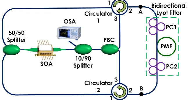
Figure 1 depicts the experimental structure of MWFL based on SOA. For the investigation of channel spacing tenability at different temperature of PMF, we used SOA manufactured from Qphotonics, model number Q1550. For the investigation of multiwavelength performance of three SOAs, the other two SOAs are manufactured from Alphion and Thorlabs, model number SAS26p and SOA1117p, respectively. The pigtail of SOA from Thorlabs is PMF and could jeopardized the performance of multiwavelength laser. The maximum bias current setting of the SOA from Qphotonics is 400 mA, while this SOA can cover wavelength range of 1500 to 1560 nm. In protecting the SOA, we have limited the current setting to 350 mA to evade any potential damage of the SOA facet. The SOA works as the gain medium and nonlinear provider. The combination of SOA with polarizer can induce a nonlinear polarization rotation (NPR) effect. Another important element in this laser structure is Lyot filter as to slice the amplified spontaneous emission (ASE) from SOA into a multiwavelength spectrum. In this work, we aligned the Lyot filter to be a bidirectional configuration of Lyot filter that is formed from a combination of a section of PMF and two polarization controllers (PCs). A 50/50 optical splitter is utilized to split the light before routing to optical circulators. These circulators are used to ensure the light is propagate only in one direction from 50/50 splitter to the bidirectional Lyot filter. Meanwhile, Port 2 of the circulators will ensure the bidirectional Lyot filter works finely. A polarization beam combiner (PBC) is used to combine both incoming lights from Port 3 of circulators. A 10/90 splitter is utilized to extract the laser output, with the remaining light propagates to the ring cavity to continue laser oscillation. The laser output is viewed by an optical spectrum analyzer (OSA) with a constant resolution and sampling data point of 0.02 nm and 10001, respectively.
Fig. 1. The multiwavelength laser structure based on SOA and bidirectional Lyot filter.
3. Operation principle
In our work, the NPR effect is obtained from SOA and its combination with a PBC. The NPR effect induces an intensity dependent loss (IDL) mechanism, subjected to a certain polarization state. The IDL mechanism is utilized as an amplitude equalizer to achieve a flat multiwavelength spectrum. At first, the ASE signal from SOA will split evenly through the 50/50 splitter before reaching the bidirectional Lyot filter through Circulator 1 and Circulator 2. The intensity of light at point A and B is approximately equal due to the same cavity length from the 50/50 coupler to the bidirectional Lyot filter. With this condition, the best flatness of multiwavelength spectrum is achieved.
In the Lyot filter, a constructive interference leads to multiwavelength generation which is based on the combination of two refracted lights at the same phase and amplitude in the PMF. The refracted lights were produced inside the birefringence medium of PMF when the polarization direction of the incoming light towards PMF is set to 45° in between the axes of PMF.
2 BL (1)
where B is the birefringence of PMF, L is PMF length and λ is the operating wavelength. In the meantime, the channel spacing is determined using
BL 2
(2)According to the equation as above, by changing the birefringence value, the channel spacing simply can be tuned. In our experimental work, we changed the birefringence value by heating up the PMF. The channel spacing was tuned due to temperature variation of PMF [17], in a temperature-controllable furnace. Equation (3) derived the other relationship of the temperature and channel spacing. From the equation [18], the channel spacing is reliant upon the difference of temperature and birefringence.
T T L B T B
Leff eff
~ (3)where Leff, ΔT and ΔB is the effective length of PMF, temperature variation and birefringence variation, respectively.
4. Results and discussions
4.1 The heating device
In this research work, a heating device is used to heat up the PMF in changing the birefringence value. The heating device is known as polarization and temperature controller (PTC) system which is manufactured by Alnair. The lowest and highest temperature settings of the PTC is 26°C and 55°C, respectively. The PTC reading is calibrated against thermocouple measurement (Proskit Digital Multimeter, MT-1860) since the PTC can be influenced by ambient temperature which will affect the displayed value. At first, we tested the PTC by inserting the thermocouple into the chamber to measure the chamber temperature. Figure 2 depicts the temperature reading showing 5°C temperature difference across the range between the set temperature and the chamber temperature. Therefore, the chamber temperature will be used as independent variable in this study. Subsequently, the PMF was inserted into the chamber after being wrapped using aluminum foil so that it will be heated evenly. Only two PMFs with different length were used; 53.2 m (PMF1) and 10.6 m (PMF2) as to study any change of temperature sensitivity in relation to the PMF length.
Fig. 2. The characterization of the chamber temperature of the PTC and its comparison with the displayed temperature.
4.2 Temperature effect of PMF to the channel spacing
45.5°C, respectively. From the channel spacing values, the temperature coefficient is 0.55 x 10⁻³ nm/°C. Meanwhile, in Figure 3(b), when shorter PMF length is used, the channel spacing is 0.506 nm, 0.502 nm and 0.474 nm as the temperature was increased in the same manner. Using this PMF2, the temperature coefficient is slightly higher at 1.46 x 10⁻³ nm/°C.
Fig. 3. The multiwavelength spectra at different channel spacing based on (a) 53.2 m and (b) 10.6 m of PMF.
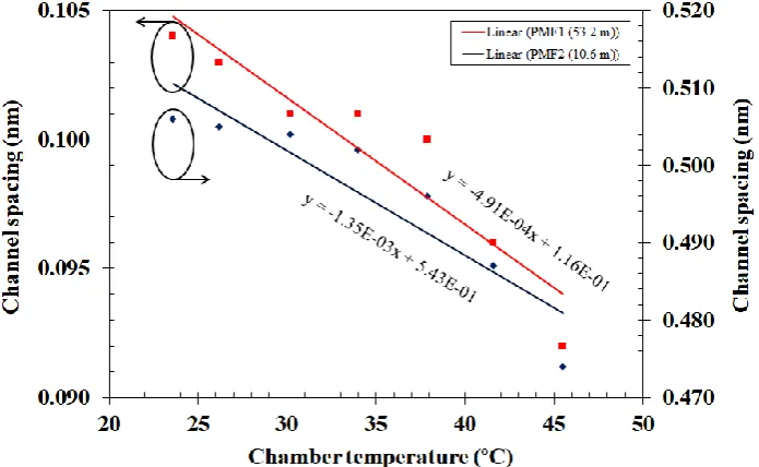
Figure 4 shows the variation of channel spacings at increased chamber temperature for PMF1 and PMF2. The figure clearly shows that the channel spacing is narrower with temperature increment. From the slope, the temperature coefficient for PMF1 is 0.49 ×10⁻³ nm/°C which nearly equal to the previous calculation as in Figure 3. Meanwhile, using shorter PMF in PMF2, the temperature coefficient from the slope is increased to 1.35×10⁻³ nm/°C. Note that the negative value is negligible since the difference value of channel spacing is always in positive value. From our observation, we found that PMF2 is more sensitive to temperature change due to higher temperature coefficient as compared to PMF1.
Fig. 4. The determination of temperature coefficient based on two different length of PMFs due to temperature increment nm/°C.
4.3 Multiwavelength performance at different SOAs
wavelength location of the lowest to the highest SOA gain according to the pattern of the ASE spectrum. We can also see that the ASE spectra have a parabolic shape and the bandwidth is quite large, which can allow flatter spectral profile with higher number of lines.
Fig. 5: ASE spectra of SOA1, SOA2 and SOA3 at their highest current setting.
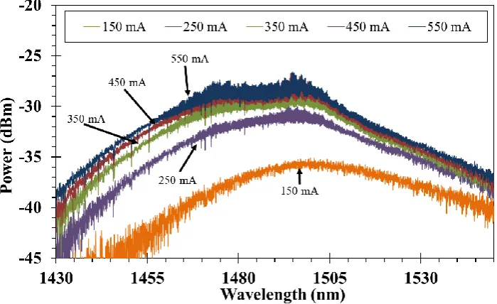
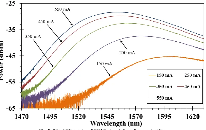
Figure 6 shows the ASE spectra of SOA2 that were taken at every 100 mA. From the figure, the peak wavelength is centered at 1490 nm and the bandwidth is wider than SOA1. Since ASE of SOA2 covers S-band region, different material is used as compared with SOA1. The highest peak power is -26 dBm, while the highest gain ripple is seen at 550 mA. The ASE spectra tend to shift to the shorter wavelength with the increment of SOA current. The shifting phenomenon occurs because the band is filled with injected electrons and holes.
Fig. 6: The ASE spectra of SOA2 at variation of current setting.
Fig. 7: The comparison of multiwavelength spectrum based on SOA1 and SOA2 at the highest current setting of 350 mA and 550 mA, respectively.
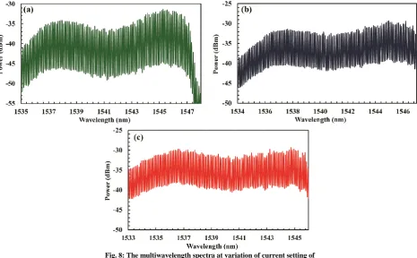
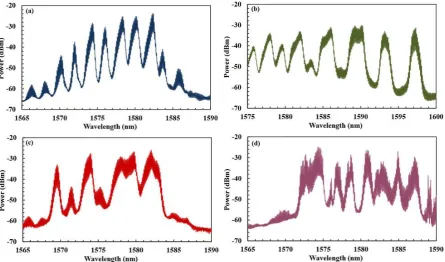
Figure 8 shows the multiwavelength spectrum using SOA2 at variation of current setting. The spectra are compared at the same wavelength span for the observation. The PCs are altered until the best spectrum is achieved. The center wavelength is at approximately 1540 nm, even though its ASE spectrum centered at 1490 nm. This is due to the fabrication and the material of SOA2 which is differ with SOA1, as well as polarization state influence to the lasing wavelengths. From the figure, the extinction ratio value is seen lower at higher SOA current. This is due to the broader bandwidth attained at higher SOA current. The gain at the higher intensity is fairly distributed among the lasing lines throughout the broader lasing bandwidth, thus leading to the lower extinction ratio value.
Fig. 8: The multiwavelength spectra at variation of current setting of (a) 150 mA, (b) 250 mA and (c) 350 mA when the SOA1 is replaced with SOA2.
at 121 and 8, respectively. The multiwavelength performances based on both SOAs are unequal due to the of different type of active material in each SOA.
Table 1: The comparison of multiwavelength performance based on SOA1 and SOA2.
SOA type Number of lines Wavelength bandwidth (nm) Extinction Ratio (dB)
SOA1 96 9.6 15
SOA2 121 12.1 8
Figure 9 shows the ASE spectra of SOA3 with variation of SOA current. From the figure, the peak wavelength is around 1550 nm and moved to shorter wavelength with the increment of SOA current. From the spectra, the SOA3 owns a benefit of wide coverage in signal amplification within the region of C-band and L-band. In the meantime, the highest peak power of ASE spectrum is at -27 dBm, which is approximately equal with SOA2. Furthermore, the ASE spectra are shown to have a smooth profile, meaning that the significant gain ripple is almost zero as compared with SOA1 and SOA2. The minimal gain ripple is due to low residual facet reflectivity within the active layer of the SOA. Hence, a flatter gain profile can be achieved due to the smooth gain profile.
Fig. 9: The ASE spectra of SOA3 at variation of current setting.
Figure 10 shows the multiwavelength spectrum when SOA1 is replaced with SOA3. The current setting is fixed to 550 mA, while the reference setting is maintained for the best comparison. It is observed that the multiwavelength spectrum is not flat over the wavelength region of L-band. From Figure 10(a), several large fringes are shown and spaced at 1.7 nm. The large fringes are due to the existence of second PMF segment at 3 m, which is the pigtail of the SOA3. There are small fringes inside the large fringes at channel spacing of 0.1 nm, which corresponds to the 53.2 m of PMF. The multiwavelength spectrum can be seen in Figure 10(b), which is the magnified view of Figure 10(a).
Fig. 10: The multiwavelength spectrum based on the SOA3. (a) The large fringes are shown to have spacing of 1.7 nm. (b) The zoom in version of (a) that clearly displays the 0.1 nm of channel spacing.
Based on the experimental setup that obtained the result of Figure 10, the PCs are then rotated to investigate the multiwavelength spectrum at polarization state dependence. The figure can be seen in Figure 11, where the spectrum change is observed with polarization state variation. Figure 11 observes the spectrum evolution from the best spectrum to the worst spectrum, starting from Figure 11(a) until Figure 11 (d). From the observation, the spacing of the large fringes is not uniform at other polarization states. The spectrum evolution shows peculiar and random spacing fringes at different PCs adjustment due to the presence of the second PMF, which is slightly farther from the 53.2 m of PMF.
From the experimental results based on SOA2 and SOA3, it is concluded that the multiwavelength performance is worse when using SOA2 or SOA3 compared with the use of SOA1. This is due to the different type of material in the active layer of the SOAs as well as the PMF pigtails as in SOA3. Overall, SOA1 has better performance in terms of multiwavelength flatness and extinction ratio value.
Fig. 11: The multiwavelength spectra at random variation of polarization states when using the SOA3.
4. Conclusion
Acknowledgement
This research was financially supported by Universiti Teknologi Malaysia under Research University Grant (Vot. No: 15H37) and by Ministry of Higher Education under Fundamental Research Grant Scheme (Vot. No: 4F936).
T
he authors extend their appreciation to the facility at Wireless and Photonics Networks Research Center, Faculty of Engineering, Universiti Putra Malaysia and UNITEN Internal Grant (UNIIG), Grant Number: J510050695.References
[1] Ahmad, H., Sulaiman, A. H., Shahi, S., & Harun, S. W. (2009). SOA-based multi-wavelength laser using fiber Bragg gratings. Laser Physics, 19, 1002–1005.
[2] Saleh, S., Cholan, N. A., Sulaiman, A. H., & Mahdi, M. A. (2018). Stable multiwavelength erbium-doped random fiber laser. IEEE Journal of Selected Topics in Quantum Electronics, 24, 1–6.
[3] Liu, T., Jia, D., Yang, T., Wang, Z., & Liu, Y. (2017). Stable L-band multi-wavelength SOA fiber laser based on polarization rotation. Applied Optics, 56, 2787–2791.
[4] Sulaiman, A. H., Zamzuri, A. K., Hitam, S., Abas, A. F., & Mahdi, M. A. (2013). Flatness investigation of multiwavelength SOA fiber laser based on intensity-dependent transmission mechanism. Optics
Communications, 291, 264–268.
[5] Sulaiman, A. H., Zamzuri, A. K., Yusoff, N. Md., Hitam, S., Abas, A. F., & Mahdi, M. A. (2011). Wavelength-spacing tunable S-band multi-wavelength fiber laser based on Lyot filter. IEEE 2nd International Conference on Photonics, 6–8.
[6] Sulaiman, A. H., Yusoff, N. Md., Cholan, N. A., & Mahdi, M. A. (2018). Multiwavelength fiber laser based on bidirectional Lyot filter in conjunction with intensity dependent loss mechanism. Indonesian Journal of Electrical Engineering and Computer Science, 10, 401–408.
[7] Chen, D., Fu, H., & Ou, H. (2008). Wavelength-spacing continuously tunable multi-wavelength SOA fiber ring laser based on Mach-Zehnder interferometer. Optics & Laser Technology, 40, 278–281.
[8] Ahmad, H., Thambiratnam, K., Sulaiman, A. H., Tamchek, N., & Harun, S. W. (2008). SOA-based quad-wavelength ring laser. Laser Physics Letters, 5, 726–729.
[9] Zhang, Z. X., Xu, K., Wu, J., Hong, X. B., & Lin, J. T. (2008). Two different operation regimes of fiber laser based on nonlinear polarization rotation : passive mode-locking and multiwavelength emission. IEEE Photonics Technology Letters, 20, 979–981.
[10] Zhang, Z., Zhan, L., Xu, K., Wu, J., Xia, Y., & Lin, J. (2008). Multiwavelength fiber laser with fine adjustment, based on nonlinear polarization rotation and birefringence fiber filter. Optics Letters, 33, 324–326.
[11] Luo, A. P., Luo, Z. C., & Xu, W. C. (2009). Channel-spacing switchable multi-wavelength fiber ring laser with one segment of polarization maintain fiber. Laser Physics Letters, 6, 598–601.
[12] Li, Y., Tian, J., Quan, M., & Yao, Y. (2017). Tunable multiwavelength fiber laser with a two-stage Lyot filter. IEEE Photonics Technology Letters. 29, 287–290.
[13] Luo, Y., Xia, L., Sun, Q., Li, W., Ran, Y., & Liu, D. (2015). Multi-wavelength fiber laser based on self-seed light amplification and wavelength-dependent gain. Optics Communications, 338, 336–339.
[14] Sulaiman, A. H., Yusoff, N. Md., Hitam, S., Abas, A. F., & Mahdi, M. A. (2013). Investigation of continuously adjustable extinction ratio in a multiwavelength SOA fiber laser based on intensity dependent transmission effect. IEEE 4th International Conference on Photonics, 151–153.
[15] Sulaiman, A. H., Yusoff, N. Md., Abu Bakar, M. H., Hitam, S., & Mahdi, M. A. (2015). Multiwavelength SOA fiber ring laser based on bidirectional Lyot filter. 1st International Conference on Telematics and Future Generation Networks, 1–4.
[16] Sulaiman, A. H., Abu Bakar, M. H., Zamzuri, A. K., Hitam, S., Abas, A. F., & Mahdi, M. A. (2013). Investigation of multiwavelength performance utilizing an advanced mechanism of bidirectional Lyot filter. IEEE Photonics Journal, 5,7101008(1-8).
[17] Kim, D. -H., & Kang, J. (2004). Sagnac loop interferometer based on polarization maintaining photonic crystal fiber with reduced temperature sensitivity. Optics Express, 12, 4490–4495.