http://www.sciencepublishinggroup.com/j/ajrs doi:10.11648/j.ajrs.20180602.11
ISSN: 2328-5788 (Print); ISSN: 2328-580X (Online)
Complex Environment Noise Barrage Jamming Eeffects on
Airborne Warning Radar
Wang Jundong
Avionics Institute of Chinese Flight Test Establishment, Xi'an, China
Email address:
To cite this article:
Wang Jundong. Complex Environment Noise Barrage Jamming Eeffects on Airborne Warning Radar. American Journal of Remote Sensing. Vol. 6, No. 2, 2018, pp. 59-63. doi: 10.11648/j.ajrs.20180602.11
Received: June 13, 2018; Accepted: July 9, 2018; Published: August 8, 2018
Abstract:
Modern warfare is carried out in a complex electromagnetic environment, where noise suppression interference directly affects the detection ability of airborne warning radar to target, in order to make airborne warning radar play its due role in battlefield. More and more requirements are put forward for radar combat capability in complex electromagnetic environment, that is, the requirement of radar anti-jamming ability in complex electromagnetic environment is becoming higher and higher. Suppression jamming is to cover or submerge useful signals with noise or similar jamming signals to prevent radar from detecting target signals. In order to evaluate the influence of suppression jamming on airborne warning radar, the influence of suppression jamming on the detection probability and detection distance of warning radar is analyzed. The variation of radar detection range and detection probability in complex electromagnetic environment compared with normal detection is given by flight test. It also provides a reference for evaluating the anti-jamming ability of airborne warning radar after being suppressed.Keywords:
Complex Eletromagnetic Environment, Oppressive Jam, Detection Probability, Detection Range1. Introduction
The work of radar in modern battlefield can not avoid the influence of complex electromagnetic environment, so the anti-jamming technology of radar in complex electromagnetic environment has become an important research topic in radar field. The electromagnetic environment of radar is becoming more and more complex, and the requirement of radar's anti-jamming capability is higher and higher. How to evaluate
the anti-jamming capability of radar in complex
electromagnetic environment has become a common concern of the radar design plant and the combat departments of the army.
In recent years, domestic radar scholars and engineers have done a lot of research on radar anti-jamming ability evaluation from theory to engineering application, and achieved good results [1-3]. However, due to the complexity of the evaluation of radar anti-jamming capability, so far, there has not been a unified method and accepted standards. In the papers [4-5] the authors simulate the noise interference and simulates the battlefield environment based on the computer simulation. The result is not high in practice. It is also difficult to account for the actual effect of use on the battlefield. In this paper, we
mainly study the electromagnetic environment formed by the target suppression jamming that the radar is facing in the future battlefield, and evaluate the anti-jamming performance of the airborne warning radar.
2. Suppression Jamming Characteristics
of Warning Radar in Complex
Electromagnetic Environment
The effectiveness of the warning radar will be weakened when it is interfered with by the enemy. Because of the multi-target detection and tracking, the jamming is mainly active suppression jamming, which directly affects the detection probability and detection distance, finally shortens the warning time and increases the threat level.
makes it impossible to detect or track the target. All kinds of jamming methods are designed to reduce the detection range of radar under the condition of prescribed detection probability and false alarm probability. In the case of simultaneous domain, same frequency domain and same space domain, radar anti-active suppression jamming is to reduce the jamming effect, that is, to reduce the drop degree of radar detection range [6-8].
Suppression jamming is to cover or submerge useful signals with noise or similar jamming signals to prevent radar from detecting target signals. Radar targets detection is based on a certain probability. If the target signal energy is compared with the noise energy, the detection threshold can be exceeded, the detection probability can be achieved under the condition of a certain false alarm probability, and the suppression jamming is to make the strong jamming power into the radar receiver [9]. The SNR is reduced as much as possible, which makes it difficult for radar to detect targets. The effect of suppression jamming is the degradation of combat performance caused by jamming of radar or combat system with radar.
3. Influence of Suppression Jamming on
Detection Probability of Warning
Radar
The detection performance of radar signal is described by its detection probability and false alarm probability. The greater the detection probability is, the greater the probability of finding the target is, and at the same time, it is hoped that the value of false alarm probability should not exceed the allowable value.
When the radar performance parameters are determined, the detection probability mainly depends on the radar environment characteristics. The suppression jamming to the warning radar is to suppress or flood the useful signal with the noise or similar jamming signal to prevent the radar from detecting the target information, which makes it difficult for the radar to detect the target. When SNR is reduced to a certain extent, radar will not be able to detect or correctly detect the target. Therefore, when the false alarm probability is determined, the detection probability of radar is an increasing function with SNR as independent variable, which changes with the change of SNR [10-11].
Generally, the jamming noise received by radar is wideband Gauss noise. The probability density function of interference received from the input of receiver is shown in equation 1:
(1)
Where
=Probability of wideband Gauss noise Voltage, = its variance.
The mean value of noise interference is zero. The voltage amplitude of the noise envelope is distributed as the function of Rayleigh, The probability density function is shown in
equation 2:
(2)
Where
r =Amplitude of noise Envelope, =Setting threshold Voltage,
= The false alarm probability when the noise envelope
voltage exceeds the threshold Voltage. It can be concluded that the relationship between false alarm probability and threshold
Voltage ( ) using equation 3:
(3)
Namely: (4)
As seen in equation 4, When the noise distribution function
( ) is fixed, the probability of false alarm ( ) depends
entirely on the threshold Voltage ( ).
The probability that the signal plus noise exceeds the
threshold is the discovery probability ( ), the signal
frequency is the center frequency of the intermediate frequency filter, and the probability density function of the output envelope of the envelope detector is shown in equation 5:
(5)
Where
=Envelope of signal plus noise, =Amplitude of signal,
is Zero order modified Bessel function with variable
,
∑
∞ 0 = 2 2 2 0)
!
(
•
2
=
)
(
n n nn
z
z
I
(6)The probability of a signal detected is the probability of
exceeding the predetermined threshold . So the probability
of discovery ( ) is shown in equation 7:
(7)
It reflects the relationship of between discovery probability
( ) and threshold Voltage ( ), also and sine wave
amplitude ( ). The relationship of between receiver signal voltage and power is shown in equation 8:
(8)
2
2
1
( ) exp( )
2 2 v P v πσ σ = − ( ) p v 2 σ 2 2 2
( ) exp( )
2
r r P r
σ σ
= − r≥0
T V fa P T V 2 2
2 2 2
( ) exp( ) exp( )
2 2 T T fa T V V r r
P V r dr
σ σ σ ∞ = ≤ ≤ ∞ =
∫
− = − 2 2 ln T faV = − σ P
( )
P r Pfa
T V d P 2 2 0
2 2 2
( ) exp( ) ( )
2 2
s
x x A xA
P x I
σ σ σ
+
= −
x
A
0( )
I z z x T V d P 2 2 0
2 2 2
( ) exp( ) ( )
2 2
T T
d s x
V V
x x A xA
P P x d I dx
σ σ σ
∞ ∞
+
=
∫
=∫
−d
P VT Pd
Using Equation 8, , From equation 4:
(9)
Taking SNR as variable and false alarm probability as parameter, the relationship of between detection probability and SNR can be obtained. The relation between detection probability and SNR is: when the false alarm probability is constant the greater the SNR is. The greater the discovery probability is, which means, when the threshold level is fixed, the discovery probability increases with the increasing of SNR. On the other hand, if the signal-to-noise ratio is constant, the probability of false alarm and the probability of discovery are smaller while the probability of false alarm is larger. When the
relative threshold increases, the false alarm
probability decreases, so does the discovery probability. It is usually hoped that the false alarm probability will increase when the probability of false alarm is fixed, and only by increasing the SNR can the false alarm probability be achieved. The effect of threshold level on detection probability and false alarm probability is consistent. The suppression jamming of warning radar in battle reduces the ratio of signal-to-noise of radar receiver and thus reduces the detection probability of warning radar.
4. Influence of Suppression Jamming on
Detection Range of Warning Radar
Radar detection range is based on certain detection probability, and the SNR of radar receiver changes with the distance between radar and target, so the detection probability of target is different in different range. The detection probability of general warning radar is 50%, which can be considered as the range of radar to detect target normally, that is, the detection distance of radar.
In the absence of interference, the power of the target echoes signal reaching the radar receiver is shown in equation 10:
(10)
Where
= Power of Radar transmitter, =Main lobe gain of Radar Antenna,
=The wavelength of electromagnetic waves emitted by radar,
=Distance between radar and target, =Radar cross section of target, =Radar system power loss factor.
In the absence of suppressing interference, the output noise of the radar receiver includes the external antenna noise and the internal noise generated when the receiver is in operation. The external antenna noise includes the radio noise reflected from the earth's surface, the earth's atmospheric radiation
radio noise and the cosmic background radiation noise. If the power of output noise in the receiver is , The signal-to-noise ratio (SNR) is shown in equation 11:
(11)
When the radar is subjected to active suppression jamming, the noise at the input end of the radar receiver is the thermal noise and the jamming signal transmitted by the electronic jammer. According to the jamming equation, the jamming signal power of the radar receiver is shown in equation 12:
(12)
Where
= Power of Jammer transmitting,
= Gain of Jammer,
= Gain of Radar Antenna in the Direction of jammer, =Bandwidth of Radar receiver,
= Bandwidth of Interference signal,
=Distance between jammer and radar.
With forms of self-defense interference,
。The jamming signal and the
target signal enter the radar receiver at the same time, therefore, the signal-to-noise ratio (signal-to-interference ratio) of the receiver's linear output can be approximately as:
(13)
At this time, the main lobe of the radar antenna is aligned to the jammer, in order to find a target in this case, it is required
the ratio of to be large enough to achieve the
minimum signal-to-noise ratio ( ) required for detection,
The corresponding operating distance is shown in equation 14:
(14)
is the Self-defense distance of Radar Anti-suppression jamming, When the target is larger than this distance, radar can not find the target, and the radar has corresponding defense ability when the distance is smaller.
5. Anti-suppression Jamming Test of a
Warning Radar
The anti-jamming performance of the radar should be characterized by a certain technical state of the jammer, which is characterized by the radar performance without interference and the difference of the maximum radar discovery distance when the jamming is exerted. The radar
2
1
/ ( / )
2
S N= A σ
2 2 1 ln 2 T fa V P σ =
(VT /σ)
2 2 3 4 (4 ) t t s P G P R L λ σ π = t P t G λ R σ L in P s in P S N =P
2
2
( )
(4 )
j j t r
J
j j
P G G B
P R B θ λ π = j P j G ( ) t G θ r B j B j R
, ( ) (0)
j t t t
R =R G θ =G =G
2
4 t t j s
J j j t
P G B P
S
J P P G R LB
σ π ≈ = / S J P P min SNR 2 min 4
t t j SJ
j j t
P G B R
P G LB SNR
σ π =
SJ
has a strong anti-jamming capability, and the value is small, and the value is large.
In view of the fact that the target airplane of radar detection performance test does not have jamming function, the target airplane does not changed in order to compare the influence of jamming on warning radar. The anti-suppression jamming test of alert radar is completed by means of close formation of jammers and target airplane. During the anti-jamming test of the alert radar in the complex electromagnetic environment, the performance test of the waring radar to the specific target airplane has been completed. At the same time, the radar working parameters and working profile of the anti-jamming test are consistent with the performance test of the specific target aircraft in the anti-jamming test, only the jammer is added for the anti-jamming test, and the warning radar is checked after the jamming is suppressed using detection range and probabilistic variation of warning radar to target aircraft. In the test, the target aircraft followed the jammer, and the seperation distance of the two planes was less than 5 km. In order to make the noise suppression jamming enter main lobe of the radar in self-defense mode with the team, the radar carrier aircraft was set to enter head-on relative to the target aircraft and the jammer. The jamming mode of the jammer is narrow band suppression interference, and the equivalent interference power spectral density is set to remain unchanged, the equivalent interference power spectral density is shown in equation 15:
EIPSD (15)
Where
=Output power of the transmitter of the jammer,
= Gain of jamming antenna,
= Bandwidth of jammer output signal,
= loss of jamming system.
A schematic diagram of the position of the radar carrier, the jammer, and the target is shown in Figure 1.
Figure 1. . . . Relative position of radar, jammer and target.
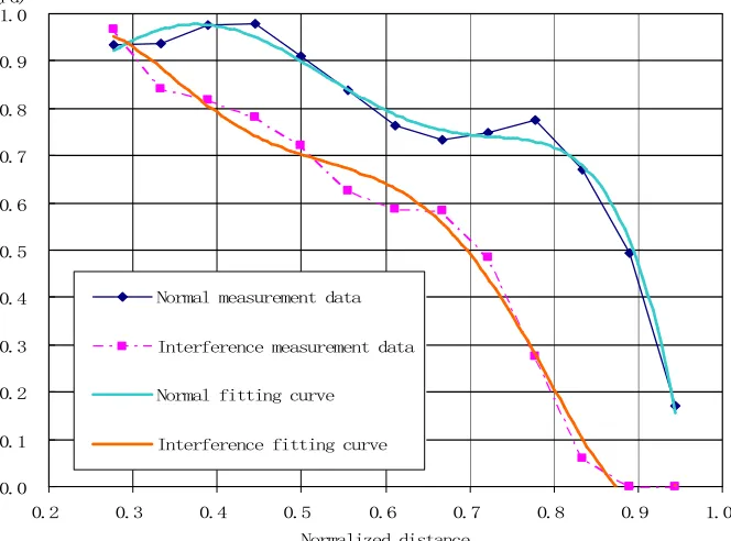
The experimental results show that the detection range of the warning radar decreases obviously when the detection probability varies with the detection range in the case of with or without suppression jamming. In Figure 2, the curves of probability and detection range are plotted in the condition of constant false alarm probability with the range of warning radar normalized.
Assuming that the entry distance between the radar and the
target is , with some interference power spectral density of
the detection range of non-jamming state warning radar is 0.86 , when the detection probability is 50%, while of the
number in jamming state is 0.67 , the detection range drops
by about 20%.
Figure 2. Relationship curve between and .
j j
j
P G
B L
× =
×
j
P
j
G
j
B
L
0
R
0
R
0
R
(Pd)
0.0 0.1 0.2 0.3 0.4 0.5 0.6 0.7 0.8 0.9 1.0
0.2 0.3 0.4 0.5 0.6 0.7 0.8 0.9 1.0
Normalized distance Normal measurement data
Interference measurement data
Normal fitting curve
Interference fitting curve
6. Conlusion
From the flight test results, it is found that with the presence of the strong electromagnetic interference environment, the operational capability of the warning radar shows a significant decline, that is, the existence of the complex electromagnetic environment on the battlefield, which hinders the display of radar operational capability. The electromagnetic environment of radar countermeasure will be more and more complex in the future battlefield. Therefore, only by fully recognizing the electromagnetic environment of radar work, grasping its
influence on radar combat capability, and taking
corresponding countermeasures, and reducing the adverse effects of the complex electromagnetic environment can the radar combat capability in the complex electromagnetic environment be better brought into operation. The evaluation of radar anti-jamming capability needs to be put forward a reasonable method according to the specific requirements to meet the operational requirements, so that it can play its due combat effect on the future battlefield.
References
[1] Guo Xinmin, Wang Xu, Wei Guohua. Evaluation method for anti-jamming performance of shore-based warning radar [J]. Systems Engineering and Electronic Technology, 2018, 40 (04): 768-775.
[2] Guo Shuxia, Zhang Lei, Dong Wenhua, Gao Ying. Characterization of dynamic characteristics of Regional electromagnetic Environment [J]. Journal of Northwest Polytechnic University. 2016, 34 (04): 703-707.
[3] Hao Xiaojun. Study on the influence Mechanism of strong electromagnetic Environment on Frequency equipment [J]. Aerospace Electronic Warfare. 2016, 32(06): 21-24.
[4] Wu Shaopeng. Research on Radar Anti-jamming Detection capability system and Technology Development [J]. Radar and Warfare, 2018, 38 (01): 1-3+17.
[5] He Zhiqiang, Zhao Feng, Zhao Bangxu, Liu Zhong, Wang Xuesong. Research on Computation Model of Radar Target Detection Probability with Noise Interference [J]. Modern Deffence Technology. 2012, 40 (1):119-123.
[6] Chen Yi, Wang Ning, Meng Jinli, Zhu Huan. Study on the system of Cognitive Radar Warfare [J]. Modern radar, 2017, 39 (09): 81-85.
[7] Li Shuhua, Huang Xiaogang, Liu Ping. A Study on Radar Anti-jamming Technology Under Complex Electro-magnetic Environment [J]. Modern Radar 2013, 35(4):1-5.
[8] Guo Shuxia, Wang Yafeng, Shan Xiongjun. Exploratory Analysis of Radar Detection Effectiveness under Complex Electromagnetic Environment [J]. Journal of Northwestern Polytechnical University 2015, 33(5):837-842.
[9] Wang Xin, Zhang Fulong, Sun Xidong, Chen feireview on Complex Electromagnetic Environmental Effects Adaptability Test and Evaluation Technology of Missile Weapon [J]. Modern Deffence Technology 2015, 43 (4). 7-11.
[10] Cui Chao, Ma Liang, Su Qi, et al. Combat Effectiveness Evaluation Method of Radar Based on Complex Electromagnetic Environment [J]. Journal of Sichuan Ordnance. 2015, 36 (7): 51-55.