R E S E A R C H
Open Access
Real-time virtual view synthesis using light
field
Li Yao
*, Yunjian Liu and Weixin Xu
Abstract
Virtual view synthesis technique renders a virtual view image from several pre-collected viewpoint images. The hotspot on virtual view synthesis area is depth image-based rendering (DIBR), which has low one-time imaging quality. To achieve high imaging quality artifacts, the holes must be inpainted after image warping which means high computational complexity. This paper proposed a real-time virtual view synthesis method from light field. Then the light field is transformed into frequency domain. The light field is parameterized and reconstructed from image array. The virtual view is rendered by resampling the light field in frequency domain. After resampling the image by performing Fourier slice, the virtual view image is obtained by inverse Fourier transform. Experiments show that our method can get high one-time imaging quality in real time.
Keywords:Light field, Virtual view synthesis, Real time, Light field imaging
1 Introduction
For many modern applications including special effects on films, TVs, and surveillance as well as virtual reality and other applications, it is often desirable to generate a high-quality virtual view image of a 3D scene from a viewpoint for which no direct information is available. The virtual view is synthesized from information from a number of known reference views (RV). Depth image-based rendering (DIBR) technique is the hotspot in virtual view synthesis field. Each pixel in RV has corre-sponding depth information. The core of DIBR is 3D image warping theory proposed by McMillan [1]. The virtual view is synthesized by re-projection of every pixel of referenced images in space.
The main drawback of DIBR technology is a low one-time image quality. The holes [2, 3], artifacts [4, 5], deformation [6], and abnormal edge [7] will appear after image warping; repair works for these issues, such as inpainting, have high computational complexity. Al-though there are a lot of recent work on improving im-aging quality in real time [8], Ho [9] and Xiao [10] reduced the computational complexity and improved operational efficiency in their work but still cannot
achieve real-time performance. Mori [11] and Zinger [12] enhanced imaging quality in their work but further increased computational complexity.
Levoy [13], the proposer of light field rendering theory, called light field the“next generation display technology” and introduced light field into computer graphics. Stud-ies on light field have gotten good results in many re-search areas, such as microscopic imaging [14], light field camera [15], complex scene 3D reconstruction [16], and accurate depth estimation [17]. Light field has shown great potential in these research works.
For the first time, this paper applies the light field the-ory to virtual view synthesis. Our method can synthesize high-quality virtual view from the light field in real time.
2 Parameterization and collection of light field Traditional cameras capture a 2D digital image, in which each pixel is the energy integration of all rays that reach the point in scene; the direction of these rays are not distinguished. The image is a projection of 3D scene, which makes the direction and position of rays lost. Light field retains the directions and positions of rays in scene.
2.1 Parameterization
In 1991, Adelson [18] proposed the concept plenoptic function, which is expressed as L= plenoptic (Vx,Vy,Vz, * Correspondence:[email protected];[email protected];
College of Computer Science and Engineering, Southeast University, Nanjing, Jiangsu Province, China
θ, ∅, λ, t). Plenoptic function is a seven dimensional function. (Vx,Vy,Vz) is the spatial position of the obser-vation point, (θ, ∅) is the light pitch angle and azimuth angle, λ is the wavelength of light, andtis the observa-tion light recording time. Taking the propagaobserva-tion of light in 3D space into account, the wavelength λ (color) gen-erally does not change. Then the plenoptic function can be reduced to five-dimensional, which is L= plenoptic (Vx,Vy,Vz,θ,∅). In most real-world scenarios, the light that imaging system collected are propagating in a lim-ited light path. Thus, light field can be represented using two reciprocal parallel planar, called light field [13] or lumigraph [19], which is expressed as L(u, v, s, t), wherein (u,v) are coordinates of the camera focal plane and (s, t) are coordinates of the image plane, as shown in Fig. 1. Light field can be understood as a certain in-tensity of light passing through the point (u,v) and (s,t) on the two planes. In this representation, a ray is repre-sented by two points in (u,v) and (s,t), so the direction and position can be determined, meanwhile the characterization of light down to four-dimensional, moreover light field can be limited into the effective area of the two planes. In practical, color information λ rep-resented by RGB channel and different frames can ex-press time information t. Therefore, light field could only focus on direction and position.
2.2 Light field collection based on camera array
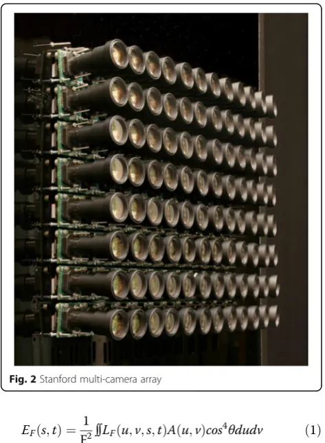
The camera array is a basic model of light field acquisi-tion equipment, which has a number of digital cameras accurately aligned in the same plane with fixed spacing. Figure 2 is the Stanford multi-camera array [20].
Equation (1) interprets the parametric form of light field. The (u,v) plane is the main lens plane and (s,t) is the image plane. LF(u,v, s, t) represents the radiation of light, while F is the distance between (u, v) and (s, t). The amount of received radiation on the image plane can be expressed asEF(s, t).θis the angle between light LF(u,v,s,t) and the (u,v) plane.A(u,v) is the pupil func-tion, which describes the impact of light coming in through the imaging system. Taking amplitude and phase of the light will change in the imaging system for instance.
EFð Þ ¼s;t
1
F2∬LFðu;v;s;tÞA uð ;vÞcos
4θdudv ð1Þ
In practical, lights are not in pupilL(u,v,s, t) = 0, Eq. (1) can be reduced to Eq. (2), which is the classical im-aging equation (imim-aging equation [21]).
EFð Þ ¼s;t
1
F2∬LFðu;v;s;tÞcos
4θdudv ð2Þ
Then by the paraxial approximation, Eq. (2) is reduced to Eq. (3); finally, an approximate digital image is calcu-lated using numerical integration.
EFð Þ ¼s;t
1
F2∬LFðu;v;s;tÞdudv ð3Þ
3 Method
In this paper, we propose a real-time virtual view synthe-sis method based on light field; the algorithm flow chart is shown in Fig. 3. First, light field is reconstructed ac-cording to the image array captured by camera array. Then, a virtual view image is synthesized by resampling the reconstructed light field, and this process is real time when light field is reconstructed.
3.1 Light field reconstruction
The photosensitive device inside camera captures im-ages. Each position on these photosensitive devices cap-tures all the light irradiation on it. Figure 4a describes
Fig. 1Parameterization of light field
how a pixel on a camera sensor is formed, whereinuplane is the plane of the main lens of the camera andsplane is the image plane of the camera; the thin lines represent the light converged on a pixel in the imaging plane through the main lens. Figure 4b describes a pixel which is formed in thesplane by overlaying a series of light pass through the main lens in theuplane. The box in Fig. 4b represents that all the light pass through the main lens and image on thesplane. The linear inside box intersects with axissat point (a, 0) means a series of light pass through the u plane forms pixel (a, 0), which is the pixel in Fig. 4a. Here,
for convenience of explanation, this example uses only one dimension each of plane (s, t) and plane (u, v). In practical, the imaging process also includes the vertical dimensionvandtof light.
In the conventional imaging process, light is projected on the image plane which makes the position informa-tion of light on thesplane recorded but does not record the location information on the u plane. However, in a camera array, the imaging process, the resultant is a multiple image array of the same scene. This is equiva-lent to placing lots of main lens on theuplane in Fig. 4, which means the position information of light on the u plane is recorded. Therefore, using camera spatial rela-tionship and imaging Eq. (3), a light field is captured.
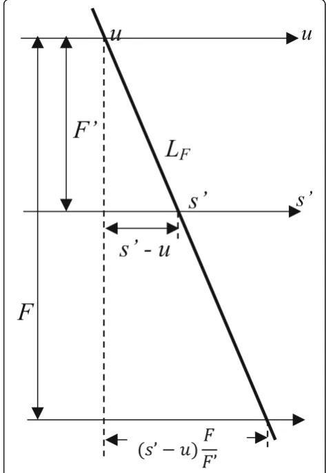
As shown in Fig. 5, the focus in different distances from the plane s'and s, in Eq. (3)F is different; the re-sult is equivalent to cutting the propagation of light in a track, different facets obtained. When camera is focused on the new plane s, F' changes into F, then expressed LF(u,s) withLF(u,s'); thus, a new image is synthesized.
As shown in Fig. 5,LFdescribed by (u, s') also can be described by (u,s). Thus, letα= F '/F, by the similar tri-angles, and then extending two-dimensional to
four-Fig. 3Framework of light field-based virtual view synthesis
Fig. 4(a) describes how a pixel on camera sensor is formed, (b) describes a pixel which is formed in s plane by overlaying a series of
Fig. 6The relationship between photographs and light fields is integral projection in the spatial domain (middle row) and slicing in the Fourier domain (bottom row)
dimensional case, the following equation can be obtained:
LF0ðu;v;s0;t0Þ ¼LF u;v;uþ
s0−u α ;vþ
t0−v α
: ð4Þ
Ng [22] have used Eq. (4) to achieve a light-field image refocusing work. In this paper, a pixel of slices of light field is calculated by Eqs. (3) and (4). Thus, any virtual view in light field is given by Eq. (5):
EðαFÞðs0;t0Þ ¼
1
α2F2∬LF u;v;uþ s0−u
α ;vþ t0−v
α
:
ð5Þ
The formula expressed that image can be taken as a slice of 4D light field project on a 2D plane. There-fore, each image in image array can be taken as a slice of the light field of a certain scene project on a 2D plane.
3.2 Resampling in frequency domain
Although the spatial relationship between the image and the light field can be visually described in space domain, but the description itself is an integral projection process, algorithm of this process usually have high computational complexity O(n4). In contrast, the rela-tionship between images and light field in frequency do-main can be simply express as an image is a 2D slice of 4D light field in Fourier domain. This conclusion stems from the fundamental theory Fourier slice theorem by Ron Bracewell [23] proposed in 1956. The classical the-ory has a great contribution later in the field of medical imaging, computed tomography scanning, and positron imaging technology.
Classic Fourier slice theorem performs a 1D projection in a 2D function; this theorem can be extended to 4D [22]. Figure 6 is a graphical illustration of the relation-ship between light fields and photographs, in both the
spatial and Fourier domains. The middle row shows that photographs focused at different depths correspond to slices at different trajectories through the ray-space in the spatial domain. The bottom row illustrates the Fourier-domain slices that provide the values of the pho-tograph’s Fourier transform. The slices pass through the origin. The slice trajectory is horizontal for focusing on the optical focal plane, and as the chosen virtual film plane deviates from this focus, the slicing trajectory tilts away from horizontal.
We use Fourier slice theorem to synthesize virtual view images based on image array. Figure 6 shows this theory in our application. Figure 7a is a synthetic virtual view. Figure 7b shows the relationship of rays between two planes, which is a number of rays through plane u will converge to a point in planes. Figure 7c shows the Fourier slice in frequency domain, which coincides with ksaxis.
The two planes parameterize light field are finite actu-ally, and the size is constrained by camera array size and other parameters. Therefore, when it comes to frequency domain, the slice is not a line but a line segment, and when it comes to space domain, it is a tangent plane which is not perpendicular to plane (u,v) and plane (s, t). As shown in Fig. 8, if the tangent is out of blue range, such as the yellow tangent, the resolution of virtual view image is deleted; if the tangent is in the blue region, such as the red tangent, the resolution of virtual view image is not deleted. Therefore, when resampling in frequency domain, in order to get a full-resolution image, the focal
Fig. 8Full resolution in finite frequency domain Fig. 9Complexity in space and frequency domain
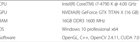
Table 1The software and hardware environment
CPU Intel(R) Core(TM) i7-4790 K @ 4.00 GHz
GPU NVIDIA(R) GeForce GTX TITAN X (16 GB)
RAM 16GB DDR3 1600 MHz
OS Windows 10 professional x64
length should be shorter than the distance between plane (u,v) and (s,t).
The process of virtual view synthesis can be trans-formed from space domain to frequency equivalently.
First, transforming light field into frequency domain, the transformation formula is:
GFðfu;fv;fs;ft;Þ ¼ g4fLFðu;v;s;tÞg: ð6Þ
Second, performing Fourier slice, the formula is:
GF‘ðfs;ftÞ ¼ 1
F2GF Ba−T½fu;fv;fs;ftT
: ð7Þ
Finally, the virtual view 2D image obtained by inverse Fourier transform, the formula is:
EFð Þ ¼s;t g2 GF0 fx;ft
: ð8Þ
Equations (6) to (8) are the resampling imaging process in frequency domain, in whichfu,fv,fs, andftare the projection of the Fourier domain.
This process reduces the computational complexity of virtual view synthesis, thereby contributing to the real-time performance of virtual view synthesis. Figure 9 is a schematic view of the complexity of algorithms in spatial and frequency domain [22]. The frequency domain light
field data can get from the collecting device, meanwhile the context of real time in this paper is after the recon-struction of light field. Therefore, computational com-plexity of operation in the frequency domain is O(n2logn) +O(n2) =O(n2logn), which is reduced a lot compared toO(n4) when operating in space domain.
4 Results and discussion
4.1 Experiment environment
The experiment environment is listed in Table 1.
4.2 Experiment 1: open dataset
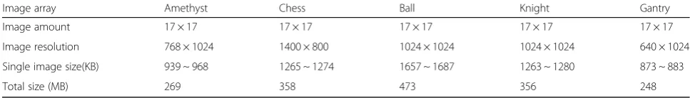
In section, the algorithm proposed in this paper will be tested and analyzed based on public light field data col-lection Stanford multi-camera array [20]. The selected data sets are“amethyst,” “chess,” “tarot cards and crystal ball” (referred to as“ball”),“knight,” and “gantry”image data arrays. Image arrays’ information is shown in Table 2.
4.2.1 Real-time performance experiment
In this section, the real-time performance is evaluated by frames per second (fps). The more frames rendered per second, the better real-time performance is.
The experimental design is as follows:
1) The viewpoint is moving along the red path in Fig.10. 2) This process lasts 18 s. From start to end, fps is
calculated each second. Thus, average fps and one-time imaging time can be obtained. Table 2Image array information
Image array Amethyst Chess Ball Knight Gantry
Image amount 17 × 17 17 × 17 17 × 17 17 × 17 17 × 17
Image resolution 768 × 1024 1400 × 800 1024 × 1024 1024 × 1024 640 × 1024
Single image size(KB) 939 ~ 968 1265 ~ 1274 1657 ~ 1687 1263 ~ 1280 873 ~ 883
Total size (MB) 269 358 473 356 248
Figure 10 is a visualization of plane (u, v) in a pa-rameterized light field. The dark square is the light field we constructed. Each dark point in dark square represents the center of a camera in camera array. The white point upper left is where the viewpoint starts. The black point lower left is where the view-point ends. The red broken line is the path which viewpoint moves along. The blue point upper left means the viewpoint is closer to that camera. The viewpoint is moving along the red path. The view-point movement trajectory covers all camera view-points, from start to end.
The results are shown in Fig. 11. Frame rate is be-tween 28 and 32 fps, which means we can render around 30 images per second.
4.2.2 Vision effect experiment
The virtual view synthesis results are shown in Fig. 12. The left column in Fig. 12 is a real view, while the right is a synthesized image in the same position.
As shown in Fig. 12, virtual view images of amethyst and chess are similar with real images. Synthesized image in ball blurs obviously.
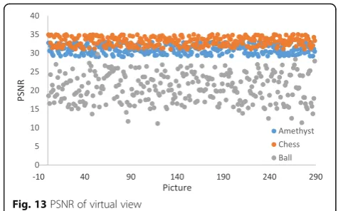
When evaluating the quality of synthesized images, we usually compare the real view image and the synthesized image. The more similar they are the better vision effect there is. PSNR is a common objective evaluation stand-ard of image quality, the unit is dB, and the greater the value, the better synthesis quality is.
Figure 13 is a PSNR distribution on amethyst, chess, and ball. The average PSNR of amethyst and chess is 31 and 32.9, which meet the basic synthetic quality virtual view requirement [24]. Ball’s average PSNR is 21.2, which is consistent with visual effects.
The reasons why we did not get good result in data set Ball are as follows:
1) This data set is a close-up image array, compared with amethyst and chess with the same space between cameras; the rays captured in ball have
Fig. 12(a) shows real and synthesized images of Amethyst, (b) shows real and synthesized images of Chess, (c) shows real and synthesized images of Ball
larger angle of incidence, which results in the attenuation effect of the incident light [25]. 2) The scene contains a relatively large transparent
object [26], which has negative influence on resampling. This is a current problem in this area, our algorithm provides no special treatment with this case, which lowers the imaging effect.
4.3 Experiment 2: simulated dataset
In this experiment, we compare the real-time perform-ance and imaging quality of our algorithm with a DIBR-based virtual view synthesis algorithm. Limited by
current studies, the data used in two virtual view synthe-sis methods do not support mutual-use. Therefore, simulation scenario is used in this experiment.
In simulation scene (Fig. 14), we use a 4 × 4 camera array with a 10-cm spacing. For DIBR algorithm, we choose cam-eras at row 2 and column 1 and column 2, the virtual view is between them. Images’resolution is 1024 × 768.
Most of studies based on DIBR in recent years is some improvements based on the framework proposed Do [24], for example, depth image preprocessing [27], improved hole-filling algorithm [28], allocation of re-sources [9], and parallelization acceleration. So in this
experiment, we selected a DIBR synthesis algorithm pro-posed by Do [24].
4.3.1 Real-time performance experiment
As shown in the 2 row of Table 3, Do’s algorithm still cannot synthesize one image within 100 ms after 128 × 128 thread CUDA acceleration. In Do’s work, one image is synthesized in 25,000~30,000 ms when implementa-tion on CPU (Do 1). Implementaimplementa-tion on GPU with 128 × 128 threads block (Do 2) reduces the time to 2300 ms; the main reason is that the latter part of the image restoration process is a complicated algorithm. The imaging time of a single image is 33 ms in our algo-rithm, which is consistent with earlier experiments and means our algorithm can achieve better real-time performance.
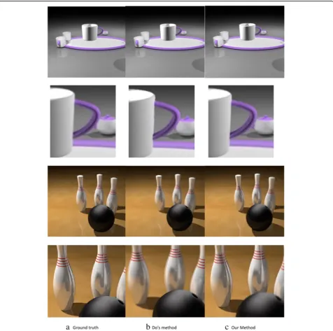
4.3.2 Vision effect comparison
As shown in Fig. 14, column (a) lists real image and the details in virtual view position, column (b) lists images synthesized by Do’s algorithm, and column (c) lists im-ages synthesized by our algorithm. In the cups scene, we can see that our result is much more similar to the ground truth at the right edge of the cup (the first and second rows in Fig. 14). In the bowling scene, there are ghost edges and blurring on the bowling pins because of the specular surface, and our result is good.
Objective evaluation results are as shown in Table 3 from 3 to 5 rows. The PSNR, MSE, and SSIM differ-ences between our method and Do’s method were small, but our algorithm has better visual result in real-time performance.
4.4 Experiment 3: light field compression
The large amount of data is a challenge to our virtual view synthesis method. This problem can be solved by taking a compression algorithm. In this experiment, we choose a light field compression algorithm proposed by Magnor [26]. Table 4 shows the size of light field and compressed light field. The bandwidth problem caused by large amount of data can be solved by using light field compression algorithm.
5 Conclusions
Traditional DIBR based virtual view synthesis method has low one-time imaging quality, and it is
time-consuming to deal with artifacts, holes, and other issues. Our light field based virtual view synthesis method pro-vides a better one-time imaging quality, and no repair work is needed after first-time imaging, which means lower computational complexity; thus, high-quality and real-time virtual view synthesis is performed in this paper. Experiments show that the virtual view synthetic methods proposed in this paper provides good perform-ance in real time and objective image quality using light field. But with transparent objects in the scene, the im-aging quality is not high enough. Tao [25] in their study has made some attempt for this issue, which is also the direction of our next study. Moreover, our method is currently only performed on image array. The amount of data will be larger when it comes to videos. Our next work is to compress light field.
Acknowledgements
This work is supported by the National High-tech R&D Program of China (863 Program) (Grant No. 2015AA015904), China Postdoctoral Science Foundation funded project (2015 M571640), Special grade of China Postdoctoral Science Foundation funded project (2016 T90408), CCF-Tencent Open Fund
(RAGR20150120), and Special Program for Applied Research on Super Computation of the NSFC-Guangdong Joint Fund (the second phase).
Authors’contributions
LY implemented the core algorithm and drafted the manuscript. WX participated in light field reconstruction and helped to draft the manuscript. YL participated in the light field compression. All authors read and approved the final manuscript.
Competing interests
The authors declare that they have no competing interest.
Received: 30 June 2016 Accepted: 6 September 2016
References
1. L Mcmillan,An Image-Based Approach to Three-Dimensional Computer Graphics(University of North Carolina, Chapel Hill, 1997)
2. Oh, K. J., Yea, S., & Ho, Y. S. (2009). Hole filling method using depth based in-painting for view synthesis in free viewpoint television and 3-D video. Picture Coding Symposium (pp.1-4).
3. S Horst, Q Matthias, B Jörg, G Karsten, M Peter, Inter-view consistent hole filling in view extrapolation for multi-view image generation. IEEE Int Conf Image Process22, 426 (2015)
4. Muller, K., Smolic, A., Dix, K., & Kauff, P. (2008). Reliability-based generation and view synthesis in layered depth video. Multimedia Signal Processing, 2008 IEEE, Workshop on (Vol.24, pp.409-427). IEEE.
5. Smolic A, Mueller K, Merkle P, et al. Multi-view video plus depth (MVD) format for advanced 3D video systems. ISO/IEC JTC1/SC29/WG11 and ITU-T SG16 Q, 2007, 6: 2127.
6. Gaurav, C., Olga, S., & George, D. (2011). Silhouette-aware warping for image-based rendering. Eurographics Conference on Rendering (Vol.30, pp. 1223–1232). Eurographics Association
Table 3Comparison between DIBR and light field
Experiment Our algorithm Do 1 (CPU) Do 2 (CUDA)
ms/Pic 33 ms 3506 ms 890 ms
PSNR 25.7 27.2
MSE 175.0 123.9
SSIM 0.89 0.9
Table 4Light field compression result
Image array Amethyst Chess Ball Knights Gantry
Original light Field (GB) 1.3 2.2 1.9 1.7 1.4
Compressed light field (MB) 87.5 65.3 100.3 73.2 84.7
7. P Merkle, Y Morvan, A Smolic, D Farin, K Müller, PHND With et al., The effects of multiview depth video compression on multiview rendering. Signal Process Image Commun24(1–2), 73–88 (2009)
8. M Sharma, S Chaudhury, B Lall, MS Venkatesh, A flexible architecture for multi-view 3dtv based on uncalibrated cameras. J. Vis. Commun. Image Represent.25(4), 599–621 (2014)
9. TY Ho, DN Yang, W Liao, Efficient resource allocation of mobile multi-view 3d videos with depth image-based rendering. IEEE Trans Mob Comput 14(2), 344–357 (2015)
10. J Xiao, MM Hannuksela, T Tillo, M Gabbouj, Scalable bit allocation between texture and depth views for 3-d video streaming over heterogeneous networks. IEEE Trans. Circuits Syst. Video Technol.25(1), 139–152 (2015) 11. Y Mori, N Fukushima, T Yendo, T Fujii, M Tanimoto, View generation with 3d
warping using depth information for ftv. Signal Process Image Commun 24(1–2), 65–72 (2009)
12. Zinger, S., Do, L., & With, P. H. N. D. (2010). Free-viewpoint depth image based rendering. Journal of Visual Communication & Image Representation, 21(s 5–6), 533–541.
13. Levoy, M. (1996). Light field rendering. Conference on Computer Graphics and Interactive Techniques (Vol.2, pp.II-64 - II-71). ACM..
14. M Levoy, R Ng, A Adams, M Footer, M Horowitz, Light field microscopy. ACM Trans Graph25(3), 924–934 (2006)
15. Ren, N., Levoy, M., Bredif, M., Duval, G., Horowitz, M., & Hanrahan, P. (2005). Light field photography with a hand-held plenoptic camera
16. C Kim, H Zimmer, Y Pritch, A Sorkine-Hornung, M Gross, Scene reconstruction from high spatio-angular resolution light fields. ACM Trans Graph32(4), 96–96 (2013)
17. Tao, M. W., Srinivasan, P. P., Malik, J., Rusinkiewicz, S., & Ramamoorthi, R. (2015). Depth from shading, defocus, and correspondence using light-field angular coherence. IEEE Conference on Computer Vision and Pattern Recognition (pp.1940-1948). IEEE Computer Society.
18. Adelson, Edward H., and James R. Bergen. The plenoptic function and the elements of early vision. Vision and Modeling Group, Media Laboratory, Massachusetts Institute of Technology, 1991
19. R Szeliski, S Gortler, R Grzeszczuk, MF Cohen,The lumigraph. Proceedings of Siggraph, 2001, pp. 43–54
20. B Wilburn, N Joshi, V Vaish, EV Talvala, E Antunez, A Barth et al., High performance imaging using large camera arrays. ACM Trans. Graph.24(3), 765–776 (2010)
21. Stroebel, & Leslie, D..Basic photographic materials and processes /. Focal Press..
22. Ng, R. (2006). Digital light field photography. (Vol.115, pp.38-39). Stanford University.
23. Bracewell, R. N.. The Fourier Transform & Its Applications. The Fourier transform and its applications /. WCB/McGraw Hill.
24. Do, L., Zinger, S., & With, P. H. N. D. (2009). Quality improving techniques for free-viewpoint dibr. Proceedings of SPIE - The International Society for Optical Engineering, 7524, 1–4.
25. Tao, M. W., Wang, T. C., Malik, J., & Ramamoorthi, R. (2014). Depth Estimation for Glossy Surfaces with Light-Field Cameras. Computer Vision - ECCV 2014 Workshops. Springer International Publishing
26. Magnor, M., & Girod, B. (2000). 3D TV: Data compression for light-field rendering. (Vol.10, pp.338-343).
27. Y Cho, K Seo, KS Park, Enhancing depth accuracy on the region of interest in a scene for depth image based rendering. Ksii Trans Internet Inf Systs 8(7), 2434–2448 (2014)
28. B Kim, M Hong, An adaptive interpolation algorithm for hole-filling in free viewpoint video. J Meas Sci Instrume8681(4), 343–345 (2013)
Submit your manuscript to a
journal and benefi t from:
7Convenient online submission
7Rigorous peer review
7Immediate publication on acceptance
7Open access: articles freely available online
7High visibility within the fi eld
7Retaining the copyright to your article