Abstract— Chemical mechanical polishing/planarization (CMP) process is a primary wafer and thin film planarization process for semiconductor fabrication. In CMP process, a diamond dresser with well-distributed diamond grits is usually applied to regenerate the surface topography of polishing pad for maintaining the wafer material removal rate (MMR). This paper aims to develop a model of reaction force on quasi-orthogonal machining by a pyramid single-diamond tool on a soft elastomer pad. Forces have been analyzed under two dressing conditions which are face dressing direction (FDD) and edge dressing direction (EDD). The reaction force model for the pad has been investigated considering geometry of diamond grit and contact areas between the diamond grit and the pad surface. The reaction force profile obtained by experiment agrees with a simulation of normal reaction forces. Results of this study can be applied to predict diamond wear rate for diamond dressing process. Furthermore it can be extended to design diamond dresser for optimum pad cutting rate (PCR) during dressing process for semiconductor fabrication.
Index Term— Force analysis, Pad dressing, Diamond quasi-orthogonal machining, CMP
NOMENCLATURE
Fn Normal force
Ft Lateral force
S Scratching force W Down force
h Groove depth on the pad
hp Height of plow up of pad material
Angle between centerline to face of the diamond grit
Angle between centerline to ridge of the diamond grit
Angle of ridge-to-ridge of the diamond grit
Angle between the projected line in a normal direction and the scratching direction
I. INTRODUCTION
Diamond dressing process plays a key role in generating the pad surface topography before and after chemical mechanical planarization (CMP) process [1-3]. The diamond dressing process involves a dresser with well diamond grits that can break up the glazed areas, remove debris and regenerate the
roughness of pad surface. The diamond dressing process can be considered equivalent to a fixed-load surface grinding process of the soft and ductile or elastomer material. During diamond dressing, the diamond grits indent into the soft pad surface by the fixed-load and move continually on the pad. Individual diamond grit can be seen as a diamond-cutting tool in the machining process. Therefore, the interaction between individual diamond grit and the pad needs to be investigated in detail. Chen and Pham [4, 5] have investigated the effect of cutting locus of diamond grit in diamond dressing process. Results show that motions of diamond grit are not only sliding on cutting path but also rotating around grit's center axis. Motions of diamond grit on cutting locus while pad dressing are illustrated in Fig. 1. The change of cutting direction can cause the change of interaction forces and contact areas between the pad surface and individual diamond grit. This can cause non-uniformity in wear mechanism of diamond grits which results in a reduction of pad dressing coefficient. For grinding process, many researchers have developed grinding force modeling [6-9] and experimentally investigated wear mechanism of diamond grit by machining force [10-12]. Some researchers [13-15] have investigated scratching by diamond indentation to analyze the relationship between indentation force and indented depth. Cui [16] has reviewed and discussed the nano-indentation on mono-crystalline, polycrystalline and amorphous materials to provide overview for relevance of tool geometry and nano-deformation mechanisms. However, most of previous studies focus on investigation of brittle material. The investigation of forces on soft elastomer pad has not been discussed in detail yet. During dressing process, down force from the polishing tool acts on the diamond grit and is then transferred to the polishing pad. This force can be separated into many parts. Damping absorbs one part of force and deformation of the pad and another cuts the pad and reacts again the diamond grit faces.
In this paper, a geometrical model of diamond grit is firstly illustrated on the basis of the actual diamond tool. Contact areas between diamond grit and the polishing pad are
Force Analysis Model for Elastomer CMP Pad
by Diamond Tool
Quoc-Phong Pham#,1, Thi Tran Anh Tuan2, Chao-Chang A. Chen3, and Ajay Gupta3
1 School of Engineering and Technology, Tra Vinh University, Vietnam 2 School of Basic Science, Tra Vinh University, Vietnam
3 Department of Mechanical Engineering, National Taiwan University of Science and Technology, Taiwan
investigated from the scratches on the pad surface. Next, the normal reaction force on diamond grit has been analyzed and simulated based on diamond dressing by face dressing direction (FDD) and edge dressing direction (EDD). Finally, the experiment of quasi-orthogonal diamond dressing has done at different levels of load. The force profiles obtained from experiment have been analyzed and compared with simulation from the model. Both simulation result and experimental data are in good agreement.
Fig. 1. Illustration of the changes of scratching angle of diamond grit
II. THEORETICALANALYSIS
A. Pyramid geometry of diamond grit
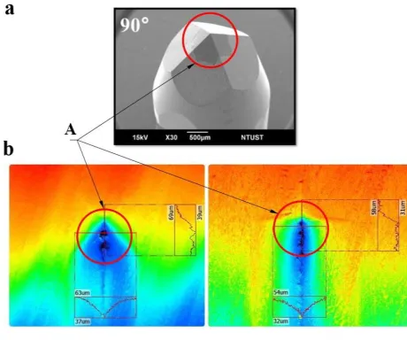
In order to develop the force model, realistic shape modeling of diamond grit is done in accordance with actual shape of the diamond tool. Then two scratches on the blank pad surface have been done by EDD and FDD. Fig. 2 presents SEM images of the single diamond tool and the scratches on the K-pad surface. In Fig. 2a, the diamond grit is a rectangular pyramid with double-couple symmetric faces. The geometry of the diamond grit is normally simplified as three main sections which includes a regular pyramid, a spherical crown at the cup of the tip, and the intersection of the spherical crown with the sides of the pyramid [17]. The spherical tip and the intersection are very small in comparison with the regular pyramid shape. Thus, the diamond grit shape in this study can be simplified as an ideal rectangular pyramid. In Fig. 2b, it is evident that the groove of EDD is deeper and larger than that of FDD. Two red circles in front of the grooves denote contact regions of the pad with diamond grit. It can be seen that while scratching the pad by EDD, the front edge of diamond grit cuts the pad and two front lateral faces of diamond grit contact the pad. In another way, while scratching the pad by FDD, a front face of
diamond grit deforms the pad material, two side edges cut the pad and two side faces of diamond grit just contacts the pad surface. As analyzed form Fig. 2, the conditions of the force model can be assumed follows as:
- The diamond grit shape is an ideal rectangular pyramid.
- In case of EDD, two faces of diamond grit contact with the pad. Hence, contact area and reaction forces could be analyzed on lateral faces of diamond grit.
- In case of FDD, three faces of diamond grit contact with the pad. Therefore, contact area and reaction forces could be considered on three faces of diamond grit.
- Diamond machining mechanism of the pad can be assumed as ideal conditions.
Fig. 2. Diamond tool and scratching on pad surface
a. SEM image of single-diamond tool; b. Confocal images of scratching on pad surface by single-diamond tool under conditions of
EDD (left) and FDD (right); A. is contact region of the pad with diamond tool
The geometric model of the diamond grit is illustrated in Fig. 3, where the base of grit is rectangle BCDE and the apex of the regular pyramid is A. There are three types of angles diamond grit angles which are , and . Because the diamond grit is assumed as a square pyramid, included scratching angle is considered as 0o and 45o for EDD and
FDD respectively. The forces acting on the diamond grit include down force due to load set-up from the machine and reaction forces due to reaction forces from the pad surface. The machined forces include down force W, scratching force S. The reaction forces include normal forces and lateral forces. Normal forces include Fnb, Fnc, Fnd, and Fne. Lateral
Fig. 3. The schematic of machining direction and forces distribution on the pyramid diamond grit
B. Analysis of contact area
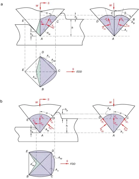
To analyze contact areas and reaction forces on diamond grit faces in detail, 2D-CAD model is developed and shown as Fig. 4. In which, vertical and horizontal projected areas of diamond grit surfaces such as Atb, Atc and Anb, Anc of ABC
and ACD, respectively. Fig. 4a and Fig. 4b depict the dressing condition as per EDD and FDD respectively. The assumption of such cases has been presented in Section II.A. The reaction force on the contact face ABC is Fnb that is
vertical to the contact face ABC. Lateral force components Ftb1 and Ftb2 lie on face ABC. Ftb1 is parallel to the base edge
BC, and Ftb2 is perpendicular to BC. However, Ftb1 equals to
zero due to its vertical orientation. Hence, Ftb1 can be ignored.
The forces on other contact surfaces of diamond grit are analyzed similarly. From Fig. 4, it can be seen that the elastic recovery and plowing of the pad during the scratching may influence the contact area. It is assumed that the elastic recovery of the material is instantly completed after the scratching and influences the size of the contact area for ductile material. Actually, the contact areas between pad and diamond grit include a groove and plow up areas of the pad. Hence, hp denotes the height of plow up of pad material and h
denotes the groove depth on the pad. The total height of diamond grit contacts pad surface can be expressed as Eq.(1)
p
h h h (1)
Due to elastic recovery of the pad, amount of pad material can recover and contact diamond grit. The contact area for elastic recovery is depicted in green regions, as shown in Fig. 5. In which, it is the height of material recovery. Hence, vertical projected area AT and horizontal
projected area AN can be obtained as follows:
T t tp te
N n np ne
A A A A
A A A A
(2)
where At, Atp and Ate are ideal, plowing, and elastic recovery
of the projected lateral contact areas; An, Anp and Ane are
ideal, plowing, and elastic recovery of the projected normal contact areas. Substituting , he and rake angles , into Eq.
(2), the contact areas of diamond grit on the pad surface can be obtained in cases of EDD and FDD as follows:
2 2 2 2 2 tan cos 2 2 tan EDD EDD e T N e hh A hA h hh
(3)
2 2 2 2 2 tan cos 2 tan 2 FDD FDD e T N e hh A hA h hh
(4)
C. Reaction forces in diamond dressing
To remove the amount of material from the pad, the diamond grit must experience sufficient energy. Such energy must be high enough to overcome the energies utilized by pad which includes frictional energy, plowing component energy dissipation and hysteresis lost energy. During scratching the pad surface, diamond grit is impacted by reaction forces from the pad surface. According to diamond grit shape, reaction forces on faces of diamond grit include lateral force FT and
normal force FN as expressed in Eq. (5) N T
FF F (5)
Normal reaction force on the diamond grit can be expressed as
N T
T N
F pA
F F
(6)
where p is the local pressure at the contact which is equal to the hardness of the pad material [13]. Lateral reaction force can be estimated by multiply of friction coefficient and normal force [18, 19]. The friction coefficient is considered for an adhesion a, a plowing p and the motion friction is
due to plowing up of the soft surface. Hence the friction coefficient may be written as Eq (7)
o T a p N A p A
(7)
Briscoe et al.[20] have experimental investigation and proposed the ratio of (τ0/p) for polymer is around 0.75. is
the shear stress at the moving contact area, the value by experimental investigation for solid polymers such as Poly methyl methacrylate, PMMA, = (0.08~0.6). The plowing coefficient of friction, µp, depends on the resistance against
plastic deformation on the horizontally and vertically projected contact area. To simplify the model, plowing coefficient of friction can be approximated to the ratio of the projected area in lateral contact surface and the projected area in the normal direction [14, 21-23]. The lateral force components can be analyzed for individual face of the diamond grit. For face ABC, the normal reaction force is Fnb,
which is vertical to the face ABC. Lateral force Ftb can be
dis-parted to two components where Ftb1 is on the face ABC and
edge BC. The angle b is the included angle between lateral
force component Ftb1 and Ftb. Normal reaction force on the
face ABC can be expressed as Eq. (8)
nb tb
F pA (8)
1 2 cos sintb nb b
tb nb b
F F F F
(9)
where b is the included angle between component of Ftb1 and
Ftb. In order to investigate the effects of forces on the face
ABC, the force components can be converted to the forces along the down force direction, W, and scratching direction, S. Hence, normal reaction force and lateral reaction force on ABC can be expressed as Eq.(10)
2
1
2
sin cos
cos cos cos sin cos
Nb nb tb
Tb nb tb tb
F F F
F F F F
(10)
The forces on the face ACD are analyzed similarly to the case of face ABC. Normal reaction force on the face ABC can be expressed as Eq.(11)
nc tc
F pA (11)
Lateral force can be divided into two components as
1 2 cos sintc nc c
tc nc c
F F F F
(12)
where c is the included angle between component of Ftc1 and
Ftc. Similar to the case of face ABC, the force components are
converted to the forces along the load direction W and scratching direction S. Hence, normal reaction force and lateral reaction force on the face ACD can be expressed as
2
1
2
sin cos
cos cos cos sin cos
Nc nc tc
Tc nc tc tc
F F F
F F F F
(13)
Total normal and lateral forces on diamond grit for both cases can be expressed as follows:
In case of EDD, =0, angles b=c=45o, as presented in
Fig. 4a. In this case, the normal and tangential forces on both faces ABC and ACD of the diamond grit of diamond grit can be expressed as Eq.(14)
EDD EDD
N Nb Nc
T Tb Tc
F F F
F F F
(14)
In case of FDD, =45o, reaction forces can act on three
surfaces of grit including ABC, ACD, and ADE, (as presented in Fig. 4b). Because the face ADE is symmetric the face ABC, the included angle between lateral force components on ADE is same that on ABC. The included angle between lateral force components on ACD, c= 90o.
Reaction forces on diamond grit can be expressed: 2
2
FDD FDD
N Nb NC
T Tb NC
F F F
F F F
(15)
Normal reaction force FN in Eq. (14) for case of EDD
and Eq. (15) for FDD are used in simulation via MATLAB to establish the relationship between depth of groove and normal force.
III. EXPERIMENT
A. Material preparation
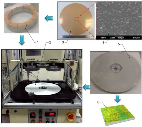
In order to implement an experiment, a solid polyurethane polymer pad (K-Pad) has been used. K-pad with dimension of 380mm × 2.19mm, is a commercial polishing pad provided by KURARAY Company, Japan. Before testing, initial roughness on K-pad surface has been removed and calibrated by truing process with diamond lapping films. The truing K-pad surface has been implemented on M15PC-Lapping machine under 02 steps with 40min for each step. Two types of diamond lapping film type 661X, 8" discs of 3MTM with diamond grit size 30µm and 15µm are used for
pad truing. The illustration of pad truing process is shown in Fig. 5. After truing, the pad sample has been cut into sectors by laser cutting. Four types of single-point diamond tools including 90-EDD, 90-FDD, 120-EDD, and 120-FDD have been used. The diamond tools are provided by EBARA Inc., Japan. To measure the normal reaction force, a force sensor typed transducer TI-702 is fixed on top of the diamond tool. To observe the deformation and plow up of material during diamond dressing, a high-speed camera Mejiro Genossen TOF-10, Nippon Hamamatsu Co., Ltd., is used.
Fig. 5. Reparation of K-pad truing process
1. Conditioning ring; 2. Platen; 3. Diamond lapping film; 4. SEM image of film surface; 5. K-pad; 6. Image of pad surface roughness after truing
B. Experimental set up
test is repeated for three times in all cases. During diamond dressing, the transducer force sensor measures the changes of the normal reaction force. Measurement data of force is collected then graphed to the force profiles by MATLAB software. The scratching surfaces of pad sample after diamond dressing have been measured by CCI Taylor machine (3D Optical Profiler).
Table I
Experimental conditions and parameters for diamond dressing
Tool/parameters Characteristic/value
Polishing Machine
Diamond grit
Polishing Pad
Downforce measurement
Roughness measurement
HAMAI HS-720C (JAPAN)
90o- EDD; 90o- FDD
120o- EDD; 120o- FDD
Solid K-type
Transducer TI-702
CCI Taylor-3D Optical Profiler
Fig. 6. Experiment set up for diamond dressing on HAMAI machine
a. Configuration of tools on HAMAI machine; b. Large scale of setting force sensor on the diamond tool set; c. Software interface for record force profile (left) and images captured by TOF-10 (right); d. Illustration of scratching direction on K-Pad; e. Illustration of force sensor set-up; f. Reaction force on diamond tool; 1. Wafer header; 2. Light source intensity adjustment; 3. Holder frame; 4. Platen; 5. Adjustment screw on y-direction; 6. Adjustment screw on z-direction; 7. Pad sample (K-pad); 8. Diamond grit holder; 9. Force sensor TI-702; 10. High speed camera (TOF-10); 11. Block screw; 12. Micro-scale ruler; 13. Plow up of pad material in front of grit; 14. Force profile
IV. RESULTS AND DISCUSSION
To investigate normal reaction force in different test conditions, profiles of reaction forces on diamond grit 90o are
shown in Fig. 7 in which Fig.7a and Fig.7b represents EDD and FDD respectively. In Fig. 7, the value of reaction force while machining increases nearly two times than that of initial setup. The profiles of reaction force have almost similar trends. Base on the variation of force value, the force profile can be divided into five main segments/steps which includes (1) remaining, (2) deformation, (3) cutting, (4) out of the cutting, and (5) sensitive force sensor. There is increase in normal reaction force on diamond grit due to deformation and clogs up of material in front of diamond grit during step two [15]. Maximum values of reaction force of tests has been selected to compare with model.
Fig. 7. Normal reaction force profiles during diamond dressing; a. for 90-EDD and b. for 90-FDD
location of the scratches to measure the depth of groove. Based on configuration of this study of low down force for elastomer pad, the diamond grits of 120o show a low
coefficient of dressing. Therefore, the pad samples having scratches by 90-EDD and 90-FDD are chosen to measure the machined depth, and then such measurement data is compared with the theoretical prediction. Measurement result of the machined depth is compared with the theoretical prediction. Measurement results of normal reaction force and groove depth of EDD and FDD are shown in Table 2. Non-uniformity of machined depth can be expressed as:
% 100%NU
(16)
NU is calculated for each level of load. From Table 2, there is the difference from NU on machined depth, the load at 400g is most suitable for both cases of EDD and FDD because of lowest NU, 5.2% for EDD and 3.48% for FDD.
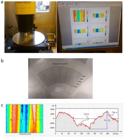
Fig. 8. Measurement of K-pad sample after diamond dressing
a. Set up on CCI machine (left) and software interface (right); b. Measurement positions on pad sample; c. CCI image of the scratch
by diamond grit 90EDD-400gam (left) and surface profile (right)
Table II
Measurement results of machined depth
Fig. 9 combines the normal reaction force obtained by theoretical prediction and experiment data as represented from Table 2. In this figure, the x-axis presents normal reaction force on diamond grit and the y-axis denotes machined depth on pad surface. Solid blue and red curves present simulation results by 90-EDD and 90-FDD respectively. Dash blue curve with right-triangle and dash red curve with left-triangle denote measurement results of normal reaction forces on grits. The depth of groove obtained by simulation is higher than that of experiment results because pad material is assumed as ideal. But in actual machining process, there is energy consumption due to material damping and machine vibration [24, 25]. From Fig. 9, it can be seen that:
- Normal force on diamond grit during cutting is two times higher than that of initial set up.
- For diamond grits at an angle of 90o, in range of
100, 200, 300, 400, and 500g of load down setup, setting at 400grams can obtain stable normal force for both case of EDD and FDD.
- EDD creates a deeper groove, less plow up, and undergoes more reaction force than FDD. Based on requirement of CMP process, polishing pad surface needs more asperity to keep slurry, but fewer grooves to increase bearing ratio. Therefore, FDD regenerate the better pad surface topography than EDD does.
Fig. 9. Comparison of reaction force between theoretical prediction and experiment under 90-EDD and 90-FDD
V. CONCLUSION
This paper has investigated an indented marks and groove depth in the diamond dressing by the single-point diamond tool to develop the model of reaction forces on diamond grit. The geometric model which considers diamond grit shape has been built and analyzed. Contact areas and reaction forces on diamond surfaces have been illustrated. The relation between reaction force and indented depth has been described for face dressing direction and edge dressing
Initial setup (g)
100 200 300 400 500
Measured force (g)
EDD 280 420 560 800 950
FDD 230 420 560 750 900
Machined depth (μm)
EDD 6.47 7.94 9.12 9.96 10.42
FDD 5.09 7.08 7.77 8.08 8.42
NU(%) EDD 11.3 7.1 7.3 5.2 6.3
direction. Normal reaction forces obtained by simulation on diamond grit face for FDD and EDD have been verified by experiment. The reason for vibration of the dresser during pad dressing and non-uniformity of pad surface after dressing has been explained. Furthermore, the analysis results can be applied to predict diamond wear rate in diamond dressing process.
REFERENCES
[1] Lawing, A. S., and Juras, C., “Pad surface analysis and conditioning effects: implications on process design, break-in response and next generation pad and conditioning platforms,” in International Conference on Planarization/CMP Technology, Dresden, Germany, 2007.
[2] Lee, H., et al., “Investigation of pad staining and its effect on removal rate in copper chemical mechanical planarization,” Thin Solid Films, Vol. 519, No. 1, pp. 259-264, 2010.
[3] Eusner, T., Saka, N., and Chun, J. H., “Breaking-in a pad for scratch-free, Cu chemical-mechanical polishing,” Journal of the Electrochemical Society, Vol. 158, No. 4, pp. 379-389, 2011.
[4] Chen, C.-C.A., and Pham, Q.-P., “Study on diamond dressing for non-uniformity of pad surface topography in CMP process,” International Journal of Advanced Manufacturing Technology, Vol. 91 Nos. 9-12, pp. 3573-3582, 2017.
[5] Pham, Q.-P., and Chen, C.-C.A., “Study on pad cutting rate and surface roughness in diamond dressing process,” International Journal of Precision Engineering and Manufacturing, Vol. 18, No. 12, pp. 1683-1691, 2017.
[6] Li, H. N., et al., “Detailed modeling of cutting forces in grinding process considering variable stages of grain-workpiece micro interactions,” International Journal of Mechanical Sciences, Vol. 126, Supplement C, pp. 319-339, 2017.
[7] Perveen, A., Rahman, M., and Wong, Y. S., “Modeling and simulation of cutting forces generated during vertical micro-grinding,” The International Journal of Advanced Manufacturing Technology, Vol. 71, No. 9, pp. 1539-1548, 2014.
[8] Sun, J. L., et al., “A predictive model of grinding force in silicon wafer self-rotating grinding,” International Journal of Machine Tools & Manufacture, Vol. 109, pp. 74-86, 2016.
[9] Zhang, Y., et al., “Analysis of grinding mechanics and improved predictive force model based on material-removal and plastic-stacking mechanisms,” International Journal of Machine Tools and Manufacture, Vol. 122, pp. 81-97, 2017.
[10] Cheng, K., et al., “Modeling and simulation of the tool wear in nanometric cutting,” Wear, Vol. 255, No. 7, pp. 1427-1432, 2003. [11] Masahiko, Y., Satoshi, N., and Motoki, T., “Tool wear of a single-crystal
diamond tool in nano-groove machining of a quartz glass plate,” Surface Topography: Metrology and Properties, Vol. 3, No. 4, pp. 044007, 2015. [12] Ramesh, S., et al., “Experimental study on machining of titanium alloy (Ti64) by CVD and PVD coated carbide inserts,” International Journal of Manufacturing Technology and Management, Vol. 17, No. 4, pp. 373-385, 2009.
[13] Zhang, F. H., et al., “Study on the machined depth when nanoscratching on 6H-SiC using Berkovich indenter: Modelling and experimental study,” Applied Surface Science, Vol. 368, pp. 449-455, 2016. [14] Chamani, H. R., and Ayatollahi, M. R., “Equivalent cone apex angle of
Berkovich indenter in face-forward and edge-forward nanoscratch,” Wear, Nos. 356-357, pp. 53-65, 2016.
[15] Jeswiet, J., et al., “Single point and asymmetric incremental forming,” Advances in Manufacturing, Vol. 3, No. 4, pp. 253-262, 2015.
[16] Cui, D.-D., and Zhang, L.-C., “Nano-machining of materials: understanding the process through molecular dynamics simulation,” Advances in Manufacturing, Vol. 5, No. 1, pp. 20-34, 2017.
[17] Patnaik Durgumahanti, U. S., Singh, V., and Venkateswara Rao, P., “A new model for grinding force prediction and analysis,” International Journal of Machine Tools and Manufacture, Vol. 50, No. 3, pp. 231-240, 2010.
[18] Arvanitaki, A., et al., “The friction and lubrication of elastomers,” Tribology Series, Vol. 30, pp. 503-511, 1995.
[19] Friedrich, K., Lu, Z., and Hager, A. M., “Overview on polymer composites for friction and wear application,” Theoretical and Applied Fracture Mechanics, Vol. 19, No. 1. pp. 1-11, 1993.
[20] Briscoe, B.J., et al., “Scratching maps for polymers,” Wear, Vol. 200, Nos. 1-2, pp. 137-147, 1996.
[21] Lafaye, S., Gauthier, C., and Schirrer, R., “Analysis of the apparent friction of polymeric surfaces,” Journal of Materials Science, Vol. 41, No. 19, pp. 6441-6452, 2006.
[22] Chen, C.-C.A., et al. “Study on quasi-orthogonal machining of elastomer pad by single-point diamond tool.” The International Journal of Advanced Manufacturing Technology 95 (2018): 2555-2565.
[23] Zhang, F., et al., “Friction behavior in nanoscratching of reaction bonded silicon carbide ceramic with Berkovich and sphere indenters,” Tribology International, Vol. 97, pp. 21-30, 2016.
[24] Zhou, L.R., et al., “Energy consumption model and energy efficiency of machine tools: a comprehensive literature review,” Journal of Cleaner Production, Vol. 112, No. 5, pp. 3721-3734, 2016.