Abstract—This work presents an analysis of fluctuating input voltages of the DC source of voltage three-phase inverter at three levels. Indeed, the two voltages have an imbalance between it. We obtain an output voltage of the inverter at three levels asymmetric and whose non-zero means value. To minimize this imbalance we propose a solution that involves inserting the terminals of each capacitor, a bridge balancing said bridge clamping. The simulation results are quite satisfactory
Index Terms—Neutral-Point-Clamped-(NPC), three level inverter, Pulse-Width-Modulation (PWM), clamping bridge, three level rectifiers.
I. INTRODUCTION
The field of application of asynchronous machines is today important changes. They are due to the development of new structures involving machines and static converters. Indeed these structures is required in applications necessitate high dynamic performance. The induction machine is usually fed by inverters at two levels. For applications of high voltage and high power, the inverter voltage three-level NPC structure is becoming increasingly used [1] -[2]-[3]. Nevertheless, the two voltages delivered by the three-phase rectifier at three levels, have an imbalance, thus obtained, the output of the inverter, an unbalanced system voltage. To remedy this problem, we propose to use a balancing bridge called bridge clamping. For this we first present the modelling and control of converters PWM three-level NPC structure, next we discuss the modelling of the induction machine in d-q reference park, its simulation empty and loaded and see the behaviour of the machine through the deferent’s parameters namely speed and electromagnetic torque. At the end we finish by showing the role of bridge clamping in stabilizing voltages delivered by the rectifier at three levels.
II. MODELING AND CONTROL
A. Rectifier Three Level [1], [4], [5], [6].
Fig.1 shows the structure of the NPC rectifier current three levels.
Manuscript received January 11, 2012, revised February 28, 2012. M. S. Djebbar and H. Benalla are with the Electrical Engineering Department, University of Constantine, Algeria (e-mail: [email protected]; [email protected])
Fig. 1. Structure of the NPC rectifier three levels
Three orders are possible for this rectifier. The most optimal is given by the relationship (1)
2 3 4 1 K K k K
B
B
B
B
=
=
(1) .With BKS control of the base of the transistor TKS.
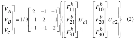
In command mode, the voltages for the rectifier expressed to the functions of half-arm connections, depending on the system (2)
⎪
⎪
⎭
⎪
⎪
⎬
⎫
⎪
⎪
⎩
⎪
⎪
⎨
⎧
⎥
⎥
⎥
⎥
⎦
⎤
⎢
⎢
⎢
⎢
⎣
⎡
⎥
⎥
⎥
⎥
⎦
⎤
⎢
⎢
⎢
⎢
⎣
⎡
⎥
⎥
⎦
⎤
⎢
⎢
⎣
⎡
⎥
⎥
⎥
⎦
⎤
⎢
⎢
⎢
⎣
⎡
− − − − − − −= . 2
30 20 10 1 . 31 21 11 . 2 1 1 1 2 1 1 1 2 3 /
1 Uc
b F b F b F c U b F b F b F c V B V A V (2)
The output currents, Ired1, Ired2 and Ired0 the rectifier at
three levels using the connect function switches are given by the following system (3).
(3)
B. Inverter Three Level [5],[6],[7]
The structure of the NPC inverter phase voltage at three levels is shown in Fig. 2. To ensure continuous operation of the inverter, it must be completely controllable. [6]
M. S. Djebbar and H. Benalla
Study of Voltage Stability Continuous Multilevel Inverter
Voltage Applied to the Induction Machine
Fig. 2. Structure of the NPC voltage inverter at three levels.
Modeling the three-phase inverter voltage at three levels is described by the following system of equations (4).
⎪ ⎪ ⎭ ⎪⎪ ⎬ ⎫ ⎪ ⎪ ⎩ ⎪⎪ ⎨ ⎧ ⎥ ⎥ ⎥ ⎦ ⎤ ⎢ ⎢ ⎢ ⎣ ⎡ − ⎥ ⎥ ⎥ ⎦ ⎤ ⎢ ⎢ ⎢ ⎣ ⎡ ⎥ ⎥ ⎥ ⎦ ⎤ ⎢ ⎢ ⎢ ⎣ ⎡ − − − − − − = ⎥ ⎥ ⎥ ⎦ ⎤ ⎢ ⎢ ⎢ ⎣ ⎡ 2 30 20 10 1 31 21 11 . . . 2 1 1 1 2 1 1 1 2 3 / 1 c b b b c b b b CM BM AM U F F F U F F F V V V (4)
C. Strategies of Command PWM
The rectifier and inverter are controlled by the same strategy PWM triangular-sinusoidal natural sampling two carriers triangular bipolar. [1],[7],[8]
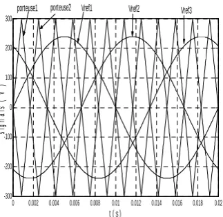
Fig. 3. Different signals the strategy triangular-sinusoidal two carriers Triangular bipolar (m = 6, r = 0.8).
The general principle is to compare a reference voltage to a triangular carrier. This strategy is characterized by two parameters:
The modulation index (m ) is defined as the ratio of the modulation frequency (fp ) of the carrier at the frequency ( f ) of the reference voltage
f
fp
m
=
(5)
The degree of modulation ( r) is he ratio of the amplitude (Vm) of the reference voltage (Vp ) to the amplitude of the carrier
Vp
Vm
r
=
(6)Triangular carriers are given by the following equations (7).
Tp t 2 Tp 3) Tp t * 4 (-Vpm Vp1(t) 2 Tp t 0 1) -Tp t * (4 Vpm ) ( Vp1 ≤ ≤ + = ≤ ≤ = t
(7) ) 2 ( 1 ) (
2 t Vp t Tp
Vp = +
Fig. 4. The pulse control of the an arm of the three-phase rectifier at three levels (m = 6, r = 0.8))
D. Machine à Induction [2]
The general equations describing the operation of cage induction machine in a referential park d-q are defined by the following system (8).
rd
dt
rq
d
I
R
V
rq
dt
rd
d
I
R
V
sd
dt
sq
d
I
R
V
sq
dt
sd
d
I
R
V
r rq r rq r rd r rd S sq S sq S sd S sdΦ
+
Φ
+
=
Φ
−
Φ
+
=
Φ
+
Φ
+
=
Φ
−
Φ
+
=
ω
ω
ω
ω
(8)The machine rotor cage is closed on itself (shorted), we take Vrd and Vrq egal zero.
By rewriting the equations in a referential precedents stationary d-q (ωS = 0), we obtain the model of the electric
part of the induction machine.
rd r rq rq r rq rq r rd rd r rd sq sq s sq sd sd s sd
dt
d
I
R
V
dt
d
I
R
V
dt
d
I
R
V
dt
d
I
R
V
Φ
+
Φ
+
=
Φ
−
Φ
+
=
Φ
+
=
Φ
+
=
ω
ω
(9)The flow equations coupled stator and rotor are obtained from own inductors Ls, Lr and mutual Msr
0 0.002 0.004 0.006 0.008 0.01 0.012 0.014 0.016 0.018 0.02 -300 -200 -100 0 100 200 300
t ( s )
s ign al s ( V )
porteuse1 porteuse2 Vref1 Vref2 Vref3
0 0.005 0.01 0.015 0.02 -0.5 0 0.5 1 1.5 B 1 1
0 0.005 0.01 0.015 0.02 -0.5
0 0.5 1 1.5
t ( s )
B 1
sq sr rq r rq
sd r s rd r rd
rq sr sq s sq
rd sr sd s sd
I
M
I
L
I
M
I
L
I
M
I
L
I
M
I
L
+
=
Φ
+
=
Φ
+
=
Φ
+
=
Φ
(10)
The equation of the electromagnetic torque of the machine is:
(
sd sq sq sd)
em
p
I
I
T
=
Φ
−
Φ
2
3
(11)
The equation of motion connecting the electrical and mechanical parts is written as follows:
r em
T
T
dt
d
J
Ω
=
−
(12)
Knowing that the rotor angular velocity ω is connected with pulsations ωs stator and ωr rotor as follows (13).
Ω
=
−
=
p
s r
'
'
ω
ω
ω
ω
p: number of pole pairs (13)
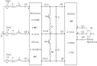
III. CASCADE RECTIFIER NPC A THREE LEVELS -NPC INVERTER A THREE LEVELS-THREE PHASE INDUCTION
MOTOR
The input bridge of this cascade consists of a rectifier at three levels associated with the three-phase voltage inverter at three levels, the two converters are controlled by the same strategy with two PWM carrier triangular (m = 36, r = 0.8). The structure of this cascade is shown in Fig.5.The cascade powers a three-phase motor considered a balanced three-phase load leading a load imposed a resistive torque Tr.
A. Application and Simulation Results
The following figures show the simulation results of the cascade shown in Fig.5.
Fig. 5. Cascade rectifier current three level- inverter voltage three-level - three phase asynchronous motor.
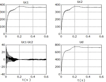
Fig. 6. Tensions intermediate the filter and their differences the rectified voltage Ured
Fig. 7. Ired1, Ired2, Ired0 the three-level three-phase rectifier
Fig. 9. Speed Ω and torque Te couple of the machine was empty and loaded
Fig. 10. The stator currents Is and Ir of rotor phase a, empty and loaded
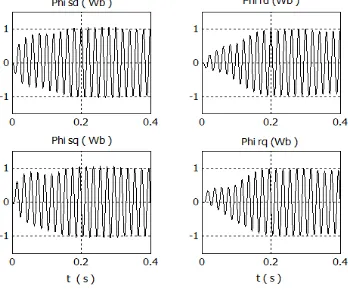
Fig. 11. Rotor and stator flux in the d-q repere
Fig. 12. Van simple voltage at the entrance of the rectifier and the inverter output
Fig. 13. Voltage and current source and THDI the current absorbed by the rectifier at three levels
Fig. 14. Voltage and current source and THDI the current absorbed by two rectifiers in series at two levels
Fig. 15. Voltage and current source and THDI the current absorbed by rectifier at two levels
B. Interpretation
The voltages UC1 and UC2 illustrated in Fig. 6 are very
close and the voltage difference (UC1 - UC2) oscillates around
the values small compared to that of UC1 and UC2. This
difference is larger for low capacity value, which causes instability of the input voltage to the inverter, and this affects the power of the machine. The decrease in the voltage difference (UC1 - UC2) is possible by increasing the carrying
It can be seen from Fig.9 the evolution of speed and the electromagnetic torque is empty and loaded. Speed attains a value very similar synchronism (157rad / s, sliding almost zero), with an almost linear increase.
Torque is highly pulsating regime transitoir hang on, it has at the time of starting of major beats, but it vanishes at steady state.The stator and rotor currents are stabilizing a necessary constant in the Magnetization of the empty machine at a nominal voltage. A perturbation torque Te = 50 Nm applied to the shaft of the machine at time t = 0.3s. Joined the electromagnetic torque value to offset this oxilllation with virtually instantaneous response, before stabilizing at the nominal value resistant torque. It can be seen in the same figure the decrease in rotor speed Ω with augmentation load resulting in slippage, which very obvious. Note it after-grading of the Fig.10, which the stator and rotor currents change depending on the load applied to the machine. The values of the stator flux and rotor Фsd, Фrd evolve proportionally to empty and loaded, but still a difference between the two flows is due to failure of the rotor relative to the stator (Fig.11)
We see the three voltage levels, 2Ured/3, Ured/2, Ured/3, presented let be the input of the rectifier to the inverter output, thus validating the simulation results well (Fig.12). It can be seen from Fig.13. That the use of three levels rectifier improves the THD much more network-side current around 4.11%. Harmonics that exist are very small in magnitude compared to the harmonic spectrum to two rectifier bridges in series at two levels (Fig. 14, THDI = 9.86), or a single bridge rectifier two levels (Fig. 15, THDI = 28.27). These results strongly justify the choice of the rectifier at three levels to generate the DC voltages to the inverter.
IV. REGULATION OF SOURCE CONTINUOUS INVERTER We observed that during the simulation of the cascade that previous input voltages of the DC source (UC1 and UC2) are
unstable and different values and the difference UC1 - UC2 is
considerable (see Fig. 6).
To minimize the imbalance between the two input voltages of the continuous source of three-level inverter is proposed to insert a bridge balancing, said clamping bridge, consisting of a transistor and a resistor the terminals of each capacitor
The transistors are controlled in such a way to maintain equal tensions UC1 and UC2. [9], [10]. Thus the new
intermediate filter between the rectifier and the inverter voltage is shown in Fig. 16.
Fig. 16. Structure of the cascade rectifier at three levels - clamping bridge - three-level inverter - induction machine
A. Modeling of the Bridge Clamping – Filter
The structure of intermediate filter is as follows
Fig. 17. Bridge structure of clamping
The model of these filters is defined by the system following (14).
2 2 2
2
1 1 1 1
1
Ir
-Ired
-Id
Ic
dt
dUc2
C2
Ir
-Id
-Ired
Ic
dt
dUc
C1
=
=
=
=
(14)
With
p 2 2
p 1 1
R
Uc
Ir
R
Uc
Ir
=
=
(15) The control algorithm of the transistors is defined as follows:
0
B
et
1
B
0
Ir
et
0
Ir
0
U
1
B
et
0
B
0
Ir
et
0
Ir
0
U
2 1
2 1
12
2 1
2 1
12
=
=
⇒
=
≠
⇒
<
Δ
=
=
⇒
≠
=
⇒
>
Δ
(16)
With: BK the control commands of the two transistors
2 1
12
Uc
-
Uc
U
=
Δ
(17)B. Application and Simulation Results
Fig. 18. Forms of continuing voltage and bridge differences without
clamping
To improve the tensions UC1 and UC2 minimizing the
simulate the same cascade but this time we use a clamping bridge.
Fig. 19. Forms of continuing voltage and bridge differences with clamping
C. Interprétation
Figure 19 shows the shapes of the voltages supplied by balancing the bridge with a value of RP = 30Ω and
capacitance values C1 = C2 = 20mF.
As we can see the difference between the input voltages of the inverter at three levels dropped considerably and reaches zero at steady state. And the voltages become equal. The results obtained are very promising for the use of this cascade in the fields of high power.
V. CONCLUSION
In this work we presented the modeling and control of PWM converters for three-levelcontrol of the induction machine. The latter has been modeled mathematically in referential Park d-q and controlled avid and in charge. The results obtained in the simulation are very satisfactory side machine or side converters.
We presented as a contribution to the study of the stability of input voltages of the inverter at three levels which allows the proper functioning of all rectifier at three levels - voltage inverter at three levels-machine induction.
We showed that these strains have an imbalance between them. This gives us a system of unstable voltage at the terminals of the machine. While the insertion of a clamping bridge across each capacitor decreases considerably the fluctuation of the input voltages of the inverter at three levels. The results were satisfactory using the filter capacitor values high enough. To reduce the value of these capacitors, while maintaining system stability, the enslavement of the voltages at the input of the inverter is recommended.
REFERENCES
[1] E. Berkouk, “Contribution to drive machines and single-phase asynchronous three-phase converters powered by direct and indirect. Application to dimmers and inverters multilevel”, Ph.D. Thesis, C.N.A.M, Paris 1995.
[2] JP Caron, JP Hautier, modeling and control of the machine asynchronous Edition Technip 1995.
[3] A. Talha, E. Berkouk , M. S. Boucherit, G. Manesse, “Study and control of two levels PWM rectifier seven levels NPC voltage source inverter cascade. Application to PMSM speed control”, UPEC, 2002, Stafford, United King Dom 2002.
[4] L. Dariusz Czarkowski, Y. Liu, P. Pillay , “ MLultivel selective harmonic elimination PWM technique in serie connected voltage inverters ”, in IEEE transactions on intustry. Application, volume 36 N°1, January/February 2000 pp 160-169.
[5] M. S, Djebbar and H. Benalla , Rectifiers comparative study between two levels and multilevel PWM order , International Journal of Electrical and Power Engineering 2(6).pp365-376, 2008
[6] E. M.Berkouk, G. Manasse, “Multi level PWM rectifier-multilevel inverter cascade. Application to the speed control of the PMSM”, IEEE proceeding, international conference on control application, Trieste,
Italy 1-4 September 1998.
[7] P. Palanivel Subhransu SekherDash, “Phase Shifted Carrier P ulse Width Modulation for Three Phase Multilevel Inverter to Minimize THD and Enhance Output Voltage Performance”, Power Electronics Laboratory, SRM University, Chennai, Tamilnadu, India - JES 2010. [8] Guedouani. R, “control of a multilevel voltage inverter. Application to
the conduct of the permanent magnet synchronous machine. ”Thesis master, ENP, Algiers, Algeria May 1998.
[9] F. Bouchafaa, E. Berkouk, M.S. Boucherit, “Analysis and simulation of a cascade of two rectifier-inverter PWM multilevel NPC. Application to conduct a MSAP”. 3rd Conférence on Electrical Engineering - Octobre 2004-Batna.
[10] R. Gue Douani, E. M.Berkouk, B. Fiali, M. S. Boucherit ,“ Analysis of the cascade rectifier-three-level voltage inverter with five levels. Application to the conduct of the permanent magnet synchronous machine” 3rd Conférence on Electrical Engineering -Octobre
2004-Batna.
Djebbar. Mohamed Salah was born in Constantine,
Algeria, 1966. Received a license electrical engineering from the University of Annaba / Algeria in 1989; Professor in Electrical engineering from 1989 to 2009 the technical school of Constantine, Algeria. A master degree in electrical machines control, 2005. Teacher in the department of electrical engineering at the University of Tebessa, Algeria. Prepare doctoral degree in electrical engineering, University of Constantine / Algeria. The research work in the field of static converters dedicated to the qualityof electric power.