ISSN (Print) : 2320 – 3765 ISSN (Online): 2278 – 8875
I
nternational
J
ournal of
A
dvanced
R
esearch in
E
lectrical,
E
lectronics and
I
nstrumentation
E
ngineering
(An ISO 3297: 2007 Certified Organization)
Website: www.ijareeie.com
Vol. 6, Issue 7, July 2017
Study and Comparison of Various Multilevel
Inverter Topologies Using Fundamental PWM
Technique
Harish Kumar K S¹, T N Raghavendra²
M. E Student [PE], Dept. of EEE, University Visvesvaraya College of Engineering, Bangalore, Karnataka, India¹
Assistant Professor, Dept. of EEE, University Visvesvaraya College of Engineering, Bangalore, Karnataka, India²
ABSTRACT: Multilevel inverters are preferred over conventional inverters as the quality of the voltage improves with the number of voltage steps at the output. A new cascaded multilevel inverter topology incorporating a new basic unit is proposed in this paper. The proposed topology utilizes fewer power electronic components to generate a specific number of output voltage levels in comparison with the classical cascaded multilevel inverters and multilevel Dc link inverters resulting in compact and cost effective design. However in comparison with cascaded multilevel inverter and multilevel dc link inverter and proposed inverter structure. As the number of voltage level ‘m’ grows the number of active switches increases according to 2*(m-1) for the cascaded H-bridge multilevel inverter and (m+3) for the multilevel dc link inverter. For the purpose of increasing the number of voltage levels with fewer number of power electronic components, hence the structure of the proposed inverter is extended.
The effectiveness of the cascaded multilevel inverter and multilevel dc link inverter and proposed inverter validated by mat lab Simulink software, results ensured the feasibility of the proposed configuration.
KEYWORDS: Cascaded Multilevel Inverters (CHBI), Multilevel Dc Link Inverters (MLDCLI), Total Harmonic Distortion (THD), and Comparison.
I. INTRODUCTION
MLI concept was first introduced in 1975. It is a power conversion device which produces an AC output voltage by using dc power sources. Multilevel inverters can produce a waveform of desired single or three phase voltage. Multilevel voltage source inverter reduces the THD of the output voltage and does not require transformers. With the increasing number of voltage levels, the power handling capability increases. Also the output waveform of staircase shape approaches to sinusoidal wave with minimum voltage stress. For increase in every level, the number of semiconductor power switches is increased.
The main function of the inverters is to convert DC input voltage to an AC output voltage of the desired magnitude. The output voltage waveforms of the inverters should be sinusoidal, however the waveform of the practical inverters are non sinusoidal and contains different harmonics. By using high speed power semi conductor devices and by using different switching techniques we can reduce the harmonic content in output voltage.
Therefore multilevel inverter (MLI) has been introduced for working with higher voltage levels due to better harmonic spectrum and high power capability. Renewable energy sources such as photovoltaic, wind and fuel cells can be utilized in MLI system for high power application. Square wave or quasi-square-wave voltages are acceptable only for low and medium power applications, but for high power applications low distorted sinusoidal waveforms are required.
II. LITERATURE SURVEY
ISSN (Print) : 2320 – 3765 ISSN (Online): 2278 – 8875
I
nternational
J
ournal of
A
dvanced
R
esearch in
E
lectrical,
E
lectronics and
I
nstrumentation
E
ngineering
(An ISO 3297: 2007 Certified Organization)
Website: www.ijareeie.com
Vol. 6, Issue 7, July 2017
inverter produces positive and negative polarity to generate an AC voltage. To reduce switching losses and device stresses, soft switching techniques can be employed. With the increase in voltage levels, MLDCL topology reduces the number of switches and gate drivers. For m number of voltage levels, the conventional multilevel inverters require 2*(m-1) switches but MLDCL inverter uses (m+3) switches. This configuration finds application in motor drives, distributed power generation involving fuel cells and photovoltaic cells.
Conventional inverter as the quality of the output voltage improves with the number of voltage steps at the output. A new single phase cascaded multilevel inverter topology incorporating a new basic unit is proposed. The proposed topology utilizes fewer power electronic components to generate a specific number of output voltage levels in comparison with the cascaded multilevel inverters resulting in compact and cost effective design.
III. SCOPE OF THE RESEARCH
MLI topologies with less number of switches reduce the initial cost and complexity. With increase in number of levels, the number of switches used is very less compared to the other MLI topology. Since switching losses reduces the efficiency of the system, fuel cell based multilevel converter with reduced switches is proposed. The main aim of this topology is to minimize the number of switches, gate driver circuits, capacitors and THD
SWITCHES REQUIRED FOR VARIOUS LEVELS
TYPE OF MLI 9LEVEL 15LEVEL 21LEVEL
Cascaded MLI 16 28 40
DC link MLI 12 18 24
Proposed MLI 9 12 15
Table 1 Switches Required For Various Levels
Compared to cascaded H-bridge MLI, MLDCL inverter reduces roughly half of the switches and gate drivers. This leads to smaller size and volume. Even though volt-ampere rating of the switches is higher, MLDCL inverters are less expensive due to the reduced number of components. The objective is to use reduced switches in MLI topology is to increase number of levels with less number of switches and sources. This topology reduces the total harmonic distortion, lowers the electromagnetic interference and produces high voltage.
IV. METHODOLOGY OF A CHB, MLDCL&PROPOSED MLI
A) CASCADED H-BRIDGE (CHB) INVERTER
In this topology, the H-bridge (single phase full bridge) inverters are connected in series. The desired output voltage is obtained by MLI from isolated dc source connected to each H-bridge. Sources are batteries and renewable energy sources such as photovoltaic and fuel cells. Number of H-bridge inverter increases as the number of level increases. Number of H-bridge inverters to be used for m level is given by the relation: Number of H-bridge to be used=( )
ISSN (Print) : 2320 – 3765 ISSN (Online): 2278 – 8875
I
nternational
J
ournal of
A
dvanced
R
esearch in
E
lectrical,
E
lectronics and
I
nstrumentation
E
ngineering
(An ISO 3297: 2007 Certified Organization)
Website: www.ijareeie.com
Vol. 6, Issue 7, July 2017
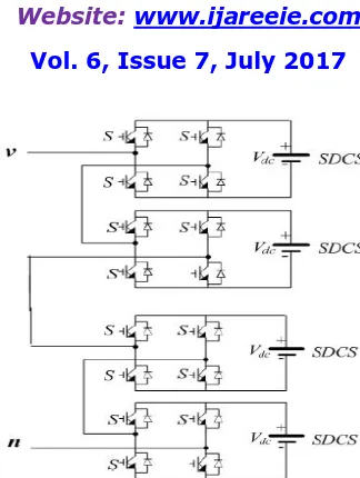
Fig 1 circuit diagram of cascaded MLI
OUTPUT
VOLTAGE S1 S2 S3 S4 S5 S6 S7 S8 S9 S10 S11 S12 S13 S14 S15 S16
0 0 0 0 0 0 0 0 0 0 0 0 0 0 0 0 0
+Vdc 1 0 0 1 0 0 1 1 0 0 1 1 0 0 1 1
+2Vdc 1 0 0 1 1 0 0 1 0 0 1 1 0 0 1 1
+3Vdc 1 0 0 1 1 0 0 1 1 0 0 1 0 0 1 1
+4Vdc 1 0 0 1 1 0 0 1 1 0 0 1 1 0 0 1
-Vdc 0 1 1 0 0 0 1 1 0 0 1 1 0 0 1 1
-2Vdc 0 1 1 0 0 1 1 0 0 0 1 1 0 0 1 1
-3Vdc 0 1 1 0 0 1 1 0 0 1 1 0 0 0 1 1
-4Vdc 0 1 1 0 0 1 1 0 0 1 1 0 0 1 1 0
Table 2 Switching Sequence for Single Phase Nine Level CHB Inverter
B) MULTILEVEL DC LINK INVERTER
Multilevel dc link (MLDCL) a H-bridge (single phase full bridge) inverter, MLDCL inverter consists of level generation cells with each cell having separate dc sources. Level generation cells produce dc voltage of staircase shape to the H-bridge inverter which in turn produces positive and negative polarity to generate an AC voltage. Compared with cascaded H-bridge MLI, MLDCL inverter reduces the number of switches and gate drivers as the level increases. (m+3) active switches are required for m number of voltage levels.
PRINCIPLE OF OPERATION: The single phase multilevel dc link (MLDCL) inverter topology, consisting of level generation cells to produce dc bus voltage of staircase shape and H-bridge inverter consists of four switches to produce positive and negative polarity to generate an AC voltage. The number of level generation cells in series generates dc source to H-bridge inverter. If m is the number of level, the number of level generation cells in the inverter is given by: Number of level generation cells =( )
ISSN (Print) : 2320 – 3765 ISSN (Online): 2278 – 8875
I
nternational
J
ournal of
A
dvanced
R
esearch in
E
lectrical,
E
lectronics and
I
nstrumentation
E
ngineering
(An ISO 3297: 2007 Certified Organization)
Website: www.ijareeie.com
Vol. 6, Issue 7, July 2017
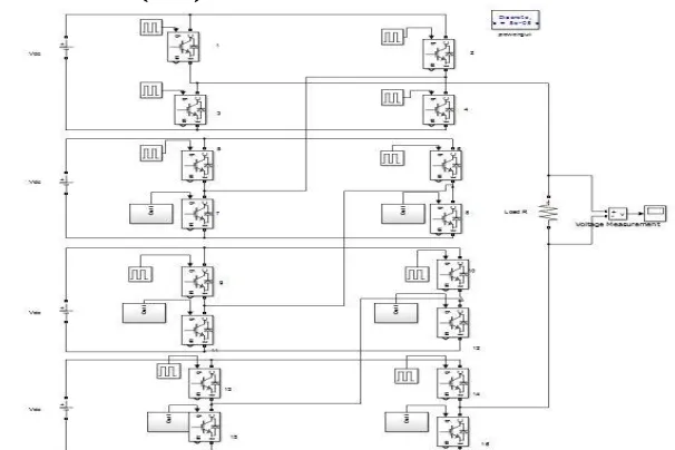
Fig 2 circuit diagram of a DC link MLI
OUTPUT
VOLTAGE S1 S2 S3 S4 S5 S6 S7 S8 S9 S10 S11 S12
0 1 0 1 0 1 0 1 0 1 0 0 1
+Vdc 0 1 1 0 1 0 1 0 1 0 0 1
+2Vdc 0 1 0 1 1 0 1 0 1 0 0 1
+3Vdc 0 1 0 1 0 1 1 0 1 0 0 1
+4Vdc 0 1 0 1 0 1 0 1 1 0 0 1
-Vdc 0 1 1 0 1 0 1 0 0 1 1 0
-2Vdc 0 1 0 1 1 0 1 0 0 1 1 0
-3Vdc 0 1 0 1 0 1 1 0 0 1 1 0
-4Vdc 0 1 0 1 0 1 0 1 0 1 1 0
Table 3 Switching Sequence for Single Phase Nine Level MLDCL Inverter
C) PROPOSED MULTI LEVEL INVERTER
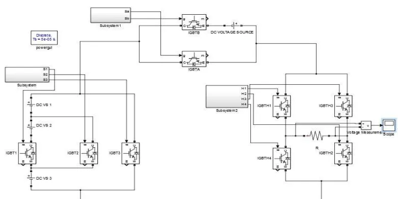
The proposed topology is depicted in Figure 3. The basic unit has three unidirectional switches (S1, S2 and S3) and three dc sources (V1, V2 and V3). Switch S1 is connected in series with the source V2 and switch S2 is connected across the source-switch assembly. Care must be taken that both the series and the parallel switch are not turned on simultaneously. The remaining sources V1 and V 3 are connected in series on either side of the source-switch assembly.
PRINCIPLE OF OPERATION: The basic unit can generate two distinct voltage levels besides zero. It can also be noted that only one of these three switches is turned on at any point in time to avoid short circuiting of the dc sources. As the lowest voltage that is generated by the basic unit is V1+V3 (2Vdc , if V1 =V3 =Vdc), an auxiliary unit is required to generate lowest step (Vdc). The basic unit together with the auxiliary unit can generate all positive the voltage steps. To generate the negative voltage steps, a polarity generator circuit (H-bridge) is connected with this basic-auxiliary unit assembly. The auxiliary unit has a dc voltage source whose magnitude is equal to the lowest voltage step (Vdc) to be generated. In addition, two unidirectional switches (Sa and Sb) are provided to include or exclude the dc source from the rest of the circuit.
ISSN (Print) : 2320 – 3765 ISSN (Online): 2278 – 8875
I
nternational
J
ournal of
A
dvanced
R
esearch in
E
lectrical,
E
lectronics and
I
nstrumentation
E
ngineering
(An ISO 3297: 2007 Certified Organization)
Website: www.ijareeie.com
Vol. 6, Issue 7, July 2017
Fig 3 circuit diagram of proposed inverter
OUTPUT
VOLTAGE S1 S2 S3 SA SB H1 H2 H3 H4
0 0 0 1 1 0 1 0 1 0
+Vdc 0 0 1 0 1 1 1 0 0
+2Vdc 0 1 0 1 0 1 1 0 0
+3Vdc 0 1 0 0 1 1 1 0 0
+4Vdc 1 0 0 0 1 1 1 0 0
-Vdc 0 0 1 0 1 0 0 1 1
-2Vdc 0 1 0 1 0 0 0 1 1
-3Vdc 0 1 0 0 1 0 0 1 1
-4Vdc 1 0 0 0 1 0 0 1 1
Table 4 Switching Sequence for Single Phase Nine Level Proposed Inverter
V. SIMULATION RESULTS
A) CASCADED H-BRIDGE (CHB) INVERTER
ISSN (Print) : 2320 – 3765 ISSN (Online): 2278 – 8875
I
nternational
J
ournal of
A
dvanced
R
esearch in
E
lectrical,
E
lectronics and
I
nstrumentation
E
ngineering
(An ISO 3297: 2007 Certified Organization)
Website: www.ijareeie.com
Vol. 6, Issue 7, July 2017
In fig 5,When each source of 5volts feeding the circuit, Output waveform of a 9level cascaded multilevel inverter insteps of 5v with an fundamental PWM switching technique using Mat lab simulink.
Fig 5 Simulated waveform of a 9level cascaded MLI
In Fig 6, when an output waveform is analyzed using FFT analysis in Mat lab simulink, Total harmonic distortion can be obtained. Here THD is about 23.65%.
Fig 6 Harmonic Spectrum of 9level cascaded MLI
B) MULTILEVEL DC LINK INVERTER
ISSN (Print) : 2320 – 3765 ISSN (Online): 2278 – 8875
I
nternational
J
ournal of
A
dvanced
R
esearch in
E
lectrical,
E
lectronics and
I
nstrumentation
E
ngineering
(An ISO 3297: 2007 Certified Organization)
Website: www.ijareeie.com
Vol. 6, Issue 7, July 2017
In Fig 8, When each source of 5volts feeding the circuit, Output waveform of a 9level DC link multilevel inverter insteps of 5v with an fundamental PWM switching technique using Mat lab simulink.
Fig 8 Simulated waveform of a 9level DC link MLI
In Fig 9, when an output waveform is analyzed using FFT analysis in Mat lab simulink, Total harmonic distortion can be obtained. Here THD is about 23.36%
Fig 9 Harmonic Spectrum of 9level Dc link MLI
C) PROPOSED MULTI LEVEL INVERTER
ISSN (Print) : 2320 – 3765 ISSN (Online): 2278 – 8875
I
nternational
J
ournal of
A
dvanced
R
esearch in
E
lectrical,
E
lectronics and
I
nstrumentation
E
ngineering
(An ISO 3297: 2007 Certified Organization)
Website: www.ijareeie.com
Vol. 6, Issue 7, July 2017
In Fig 11, When each source of 5volts feeding the circuit, Output waveform of a 9level Proposed multilevel inverter insteps of 5v with an fundamental PWM switching technique using Mat lab simulink.
Fig 11 Simulated waveform of a 9level Proposed MLI
In Fig 12, when an output waveform is analyzed using FFT analysis in Mat lab simulink, Total harmonic distortion can be obtained. Here THD is about 15.61%
Fig 12 Harmonic Spectrum of 9level Proposed MLI
VI CONCLUSIONS
The inverter implemented now can produce nine level voltages but with the modification to the inverter we can achieve more levels with which the THD at the output is further reduced. There is further scope to reduce the switch count and also number of carrier signals in modulation technique used. Advanced modulation techniques can be applied.
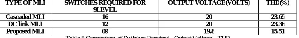
TYPE OF MLI SWITCHES REQUIRED FOR 9LEVEL
OUTPUT VOLTAGE(VOLTS) THD(%)
Cascaded MLI 16 20 23.65
DC link MLI 12 20 23.36
Proposed MLI 09 19.8 15.51
Table 5 Comparison of Switches Required - Output Voltage – THD
ISSN (Print) : 2320 – 3765 ISSN (Online): 2278 – 8875
I
nternational
J
ournal of
A
dvanced
R
esearch in
E
lectrical,
E
lectronics and
I
nstrumentation
E
ngineering
(An ISO 3297: 2007 Certified Organization)
Website: www.ijareeie.com
Vol. 6, Issue 7, July 2017
REFERENCES
[1] S.Malathy, R.Ramaprabha “A New Single Phase Multilevel Inverter Topology with Reduced Number of Switches” Department of Electrical and
Electronics Engineering, SSN College of Engineering, Rajiv Gandhi Salai, Kalavakkam, Chennai, India.2016
[2] Nagaraja Rao, Ashok Kumar and Ch.Sai Babu, “New Multilevel Inverter Topology with Reduced Number of Switches Using Advanced
Modulation Strategies,” International Conference on Power, Energy and Control (ICPEC), pp.693-699, 2013.
[3] Ammar Masaoud, Hew Wooi Ping “New Three-Phase Multilevel Inverter With Reduced Number of Power Electronic Components”, Ammar
Masaoud, Hew Wooi Ping, Member, IEEE, Saad Mekhilef, Senior Member, IEEE.
[4] G. Madhu Sagarbabu, Mr. G. Durga Prasad and Dr. V. Jagathesan, “Multilevel DC-link Inverter Topology with Less Number of Switches,”
Advances in Electronics and Electrical Engineering, vol.4, no.1, pp.67-72, 2014
[5] A.Venkadesan, Priyatosh Panda, Priti Agrawal and Varun Puli, “Cascaded H-Bridge Multilevel Inverter for Induction Motor Drives,” IJRET:
International Journal of Research in Engineering and Technology, vol.3, issue.5, May-2014
[6] Rashid. M.H, “Power Electronics circuits devices and applications”, PHI 3rdedition, 2004 edition, New Delhi
[7] P.S.Bhimbhra "Power Electronics" Khanna Publishers, New Delhi, 2003. 4th Edition