232 | P a g e
OPTIMIZATION OF PROCESS PARAMETER FOR
MULTISPINDLE DRILLING MACHINE BY USING
TAGUCHI METHOD
Mr.K.K.Powar
1, Prof. (Dr) V.R.Naik
2, Prof.G.S.Joshi
31
Research Student,
2Prof. & H.O.D.
3Prof. (T.P.O.)
Mechanical Dept., DKTE’s Textile and Engineering Institute, Ichalkaranji (India)
ABSTRACT
This paper Investigates effects of Process parameter on various drill diameter by input parameters speed, feed
and checking effects on response parameter torque, Thrust and Surface finish. The Response parameters are
checked on calibrated Dynamometer (Torque, thrust). By using Taguchi Method Investigation is done. The
Methodology for above experimentation is presented in this paper along with result and experimental setup.
Keywords: Taguchi method, Dynamometer Thrust, Torque, Surface finish.
I.
INTRODUCTION
Drilling creates cylindrical hole in solid material, mention above multispindle systems[1].The Multispindle
drilling Head are in different orientation[2]. The Special Purpose Machine (SPM)is machine that is useful to
specific component. Number of machining processes can do on single machine which is made for only that
component[3]. Productivity depends upon many factors, one of the major factors being manufacturing efficiency
with which the operation activities are carried out. Productivity can be improved by reducing the total
machining time, combining the operations[4]. The purpose of this paper is to study the effect of process
parameters such as spindle speed and feed, on thrust force and torque generated during drilling of Aluminum
Alloy material of grade AlSi9MnMg using high speed steel (HSS) drill bit. Feed of drilling depends on torque
and thrust[5]. Higher value of feed damage works whereas lower one affects cycle time. Drill diameter is the
main contributing factor.
II.
MATERIAL
AND
COMPONENT
Component under investigation and design of Multispindle drilling head is having the following material
specifications[4],
Table I: Material Composition of The ALSI9mnmg
Si% Fe% Cu% Mn% Mg% Zn% Pb% Ni% P% Ti% S% Sr% Al%
233 | P a g e
Fig.1: Sample Components Developed For Torque Measurement
III.
METHODOLOGY
Experimentation is carried out using VMC (VICTOR make) which enables high precision machining specimen
was rigidly held by the fixture which is attached to the dynamometer mounted on the machine table. The thrust
force generated during cutting was measured with the help of INTELLECTUAL make dynamometer
(Specification:-Drill Diameter Ø 12mm, Torque 20 kgf-m, Thrust200kgf). The data collected was transferred to
a computer. After studying literature it can be concluded that, controllable factors are spindle speed and feed for
drilling operation[2]. The selection of cutting parameters and their levels (table II) have been made based on
literature review, as it is widely used under common machining conditions. After studying factor, Taguchi
method is used for parameter optimization and L9 orthogonal array is used (table III).
During Experimentation following steps were followed
Fig.1: Dynamometer Setup Fig .2 Surface tester
1. Sutable fixture was design for connecting dynamometer for testing purpose.
2. A clamp was designed to fit on table.
3. Two holes of M6 are provided on dynamometer to fit testing component
4. The set for experimentation is shown in fig.1
5. A flange 2 is designed for mounting the component 3 to be tested on the dynamometer1 As shown in fig.1
6. The drill from SPM created necessary torque and thrust was measured with help of dynamometer1
7. The results were obtained as seen on the DPM (Digital Panel meter).
234 | P a g e
IV.
EXPERIMENTATION
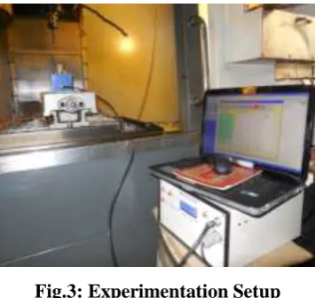
Fig.3: Experimentation Setup
Experimentation is carried out using Dynamometer .The setup is shown in fig.3, which show that
electromechanical dynamometer with software interfacing[5]
4.1 Taguchi Method
Taguchi defines the quality of a product in terms of the loss imparted by the product to the society from the time
products are shipped to the customer. Some of these losses occur due to the deviation of the products’ functional
characteristics from its desired value and these are called losses due to functional variation. Uncontrollable
factors, which cause the functional characteristics of a product to deviate from their target values, are known as
noise factors. Taguchi recommends analysing the means and S/N ratio using conceptual approach which
involves graphing the effects and identifying the factors visually that appear to be significant without using
ANOVA, which makes the analysis simple. The characteristics of the S/N ratio are given by the following
equations.
Larger the better Characteristic:
Nominal is the better characteristic: 10log
Smaller is the better Characteristic:
Taguchi-based optimization technique has produced a unique and powerful optimization discipline that differs
from traditional practices[1]. This approach can economically satisfy the needs of problem solving and design
optimization with minimum number of experiments. The proposed method is employed to determine the optimal
values of cutting speed (Vc), feed (Fr), for a given drill diameter (d) to optimize cycle time, hole size and
surface finish. For present work, a characteristic of the S/N ratio smaller is better taken is considered.
4.2 Factors and levels
Table II:
Factors and levels
Code Factor
Levels
1 2 3
A Spindle speed rpm(N) 934 1324 2504
235 | P a g e
In this experimentation there are two factors and each having three levels, so L9 array are selected.
For L9 orthogonal array the levels of input parameters are in tabulated form as follows as taking three response
parameter torque thrust surface finish there is three L9 response array
Table III: L9 Orthogonal array
Trial No. A B
1 1 1
2 1 2
3 1 3
4 2 1
5 2 2
6 2 3
7 3 1
8 3 2
9 3 3
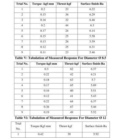
The measured response in tabular form as follows:
Table IV: Tabulation of Measured Response For Drill Diagram Ø 5.5
Trial No. Torque -kgf-mm Thrust-kgf Surface finish-Ra
1 0.2 23 6.22
2 0.15 36 6.29
3 0.16 32 6.46
4 0.2 44 6.3
5 0.17 24 6.14
6 0.15 25 5.58
7 0.13 26 5.59
8 0.12 25 6.31
9 0.11 23 5.46
Table V: Tabulation of Measured Response For Diameter Ø 8.5
Trial No. Torque-kgf-mm Thrust-kgf Surface finish-Ra
1 0.3 62 6.37
2 0.22 42 6.21
3 0.18 63 5.7
4 0.17 65 5.69
5 0.16 60 5.51
6 0.12 41 5.43
7 0.22 64 6.37
8 0.36 67 5.46
9 0.19 49 5.52
Table Vi: Tabulation of Measured Response For Diameter Ø 12
Trial
No. Torque-Kgf-mm Thrust-kgf Surface finish-Ra
236 | P a g e
2 0.27 36 6.72
3 0.23 31 5.44
4 0.28 47 6.38
5 0.31 37 6.53
6 0.27 35 5.6
7 0.31 32 6.73
8 0.35 35 5.66
9 0.38 37 5.94
V.
RESULT
AND
DISCUSSION
By using Minitab software the results are as follows
For drill 5.5
2504 1324 934 0.17 0.16 0.15 0.14 0.13 0.12 0.100 0.075 0.050 speed M e a n o f M e a n s feed
Main Effects Plot for Means for torque for drill dia 5.5mm
Data Means 2504 1324 934 32 30 28 26 24 22 0.100 0.075 0.050 speed M e a n o f M e a n s feed
Main Effects Plot for Means for thrust for drill dia 5.5
Data Means 2504 1324 934 6.3 6.2 6.1 6.0 5.9 5.8 5.7 0.100 0.075 0.050 speed M e a n o f M e a n s feed
Main Effects Plot for Means forsurface finish for drill dia5.5
Data Means
Fig.4: Main Effect Plot For Means For Torque, Thrust and Surface Finish For Drillø5.5mm
5.1 Main Effect Plot For Drill Dia 5.5 The Effect Of Torque, Thrust And Surface Finish On
Speed and Feed
[3]Characteristics for signal to noise ratio for feed time is smaller is better, for hole size is also smaller is better
because in the component drawing the positional accuracy for the holes is given at maximum material condition
and the material is maximum when hole size is small. From fig. 4, signal to noise ratio for cycle time is less for
spindle speed (N=2504rpm) and feed (Fr=0.1mm/rev).
For drill 8.5
2504 1324 934 0.250 0.225 0.200 0.175 0.150 0.100 0.075 0.050 speed M e a n o f M e a n s feed Main Effects Plot for Means for torque for drill dia 8.5
Data Means 2504 1324 934 64 62 60 58 56 54 52 50 0.100 0.075 0.050 speed M e a n o f M e a n s feed Main Effects Plot for Means for thrust for drill dia 8.5
Data Means 2504 1324 934 6.2 6.1 6.0 5.9 5.8 5.7 5.6 5.5 0.100 0.075 0.050 speed M e a n o f M e a n s feed
Main Effects Plot for Means for surface finish for drill 8.5
Data Means 2504 1324 934 6.2 6.1 6.0 5.9 5.8 5.7 5.6 5.5 0.100 0.075 0.050 speed M e a n o f M e a n s feed Main Effects Plot for Means for surface finish for drill 8.5
Data Means
237 | P a g e
5.2 Main Effect Plot For Drill Dia 8.5 The Effect of Torque, Thrust and Surface Finish On
Speed And Feed
Characteristics for signal to noise ratio for feed time is smaller is better, for hole size is also smaller is better
because in the component drawing the positional accuracy for the holes is given at maximum material condition
and the material is maximum when hole size is small. From fig. no. 5signal to noise ratio for hole size is less
for spindle speed (N=1324 rpm) and feed (Fr=0.1mm/rev). From above it is clear that the optimize parameters
are spindle speed (N) 1324 rpm and feed (Fr) is 0.1mm/rev.
The data sequences have smaller is better characteristics. From above graphs it is clear that the optimize
parameters is feed (Fr) is 0.1mm/rev.
For drill 12
2504 1324 934 0.350 0.325 0.300 0.275 0.250 0.100 0.075 0.050 speed M e a n o f M e a n s feed Main Effects Plot for Means for torque for drill 12
Data Means 2504 1324 934 40 35 30 25 0.100 0.075 0.050 speed M e a n o f M e a n s feed Main Effects Plot for Means for thrust for drill dia12
Data Means 2504 1324 934 6.3 6.2 6.1 6.0 5.9 5.8 5.7 5.6 5.5 5.4 0.100 0.075 0.050 speed M e a n o f M e a n s feed Main Effects Plot for Means for srface finish for drill dia12
Data Means
Fig.6: Main Effect Plot For Means For Torque, Thrust and Surface Finish For Drillø12mm
5.3 Main Effect Plot For Drill Dia 12 The Effect of Torque, Thrust and Surface Finish On Speed
and Feed
Characteristics for signal to noise ratio for feed time is smaller is better, for hole size is also smaller is better
because in the component drawing the positional accuracy for the holes is given at maximum material condition
and the material is maximum when hole size is small. From fig. 6 signal to noise ratio for hole size is less for
spindle speed (N=934 rpm) and feed (Fr=0.1mm/rev). From above it is clear that the optimize parameters are
spindle speed (N) 934 rpm and feed (Fr) is 0.1mm/rev.
The data sequences have smaller is better characteristics. From above graphs it is clear that the optimize
parameters is feed (Fr) is 0.1mm/rev.
VI.
CONCLUSIONS
From experimental investigation it was observed that,
1. Drill diameter of 5.5 with Feed is 0.1 mm/rev and speed 2504rpm offered optimum torque0.111kgf-m (111
N-mm), thrust 23.3kgf (233N)and surface finish Ra 5.46.
2. Drill diameter of 8.5 with Feed is 0.1 mm/rev and speed 1324rpm offered optimum torque0.120kgf-m (120
N-mm), thrust 41kgf (410N)and surface finish Ra 5.43.
3. Drill diameter of 12 with Feed is 0.1 mm/rev and speed 934rpm offered optimum torque0.23kgf-m (230
N-mm), thrust 31kgf (310N)and surface finish Ra 5.44.
Hence, while working on AlSi9 alloy by using HSS drills, higher spindle speed are recommended for process
parameter range under consideration. Cutting torque is significantly influenced by drill diameter. Higher the
238 | P a g e
REFERENCES
[1]. V.N. Gaitonde, S.R. Karnik, B.T. Achyutha, B. Siddeswarappa–“Taguchi optimization in drilling of AISI
316L stainless steel to minimize burr size using multi-performance objective based on membership function”.
Journal of Materials Processing Technology. 202 (2008), PP374–379.
[2]. Masakazu Soshi, Haruki Ishiguro, Kazuo Yamazaki –“A study on the development of a multi-purpose
spindle system for quality productive machining”. CIRP Annals- Manufacturing Technology 58 (2009),PP
327–330.
[3]. T. Lakshmi Narayanan, S. Madhavan, AnkurSinha– “Investigation of Thrust, Torque and Dclamination on
drilling of Glass fabric/Polypropylene matrix composite”. 2010 International Conference on Mechanical &
Electrical Technology (ICMET 2010),PP99-103
[4]. L.N. Lo´pezdeLacalle, A.Ferna´ndez, D.Olvera, A.Lamikiz, D.Olvera,C. Rodrı´guez, A. Elias-“Monitoring
deep twist drilling for a rapid manufacturing of light high-strength parts”.Elesvier Science Direct Mechanical
Systems and Signal Processing 25 (2011)2745-2752.
[5]. Murthy B.R.N., Lewlyn L.R. Rodrigues and AnjaiahDevineni- “Process Parameters Optimization in GFRP
Drilling through Integration of Taguchi and Response Surface Methodology”.Research Journal of Recent