©2016 JNAS Journal-2016-5-4/133-138 ISSN 2322-5149 ©2016 JNAS
Simultaneous Implementation of STATCOM and
SVC to Control the Reactive Power of Hybrid
Wind Turbines
Abbas Khorshidi
Electrical Engineering Department of Abadan Oil Refining Co.Iran
Corresponding author: Abbas Khorshidi
ABSTRACT: The use of the isolated hybrid power systems is being popular due to thecontinuous increasing gap between demand and supply of conventional energy sources and intermittent nature of non- conventional energy sources. Normally, the non-conventional energy source such as wind have induction generator to generate electricity but induction generators require reactive power for its operation and this demand is continuously changing by the variation of load and wind power. The synchronous generator used in hybrid system for generating power through diesel system is supplying reactive power to the system partially; therefore, another source of reactive power is required to fulfill this demand. In this paper, the static VAR compensator (SVC) and static synchronous compensator (STATCOM) using a proportional- integral controller (PI) are used as reactive power compensator. The dynamic performance of SVC and STATCOM are investigated for wind-diesel and wind -diesel-microhydro power systems ate constant slip operation of induction generators. The results show that the STATCOM is a better option than that of SVC for reactive power control of the hybrid system.
Keywords: hybrid wind power system; energy sources;renewable energy sources; synchronous generator; SVC and STATCOM.
INTRODUCTION
134
terminal voltage in discrete steps. Large values of capacitors and reactors are required in SVC scheme [13]. STATCOM [14] - [16] employs a voltage source inverter (VSC) that internally generates inductive/capacitive reactive power which has the advantages over the SVC scheme [17].This paper presents dynamic stability study of wind-diesel and wind-diesel-microhydro systems with realistic load power disturbance. The realistic comprises 1% step increase plus band limited white noise signal. SVC and STATCOM are used for control of reactive power in the system. The gains of the controllers with SVC and STATCOM have been optimized and optimum transient responses are shown.
Dynamic model of the System
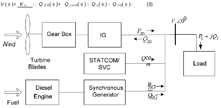
The wind-diesel power system in general comprises induction generator, synchronous generator, electrical loads and reactive power compensator (SVC or STATCOM) and a control mechanism. A single line diagram of the system is shown in Figure 1. The active power demand of the load is fulfilled by the synchronous generator and the induction generator. The reactive
Power required for the operation of induction generator and load is provided by synchronous generator and SVC/STATCOM and equations for the system shown in Figureure1 is given by,
PIG P S G PL (1) Q S
G + Q c o m = Q
L + QIG (2)
Due to disturbance in load reactive power Q L, the system voltage may change which
results incremental change in reactive power of other components. The net reactive power surplus is QS G+Qc o m−QL−QIG and it will change the system voltage which will
govern by the following transfer function equation.
V ( s )= K v Q S G( s )+ Q c o m( s ) - Q L( s ) - Q I G( s (3)
Figure 1. Single line diagram of awind diesel power system
The incremental change in reactive power of the synchronous generator Q S Gin equation
(3) depends
upon Eq′and V . The corresponding transfer equation is given by,
Q S G( s )= K 1
′ ( s ) +K2 V ( s )
(4)
135
The transfer function equation for the state variable Eq′( s)is obtained from the fluxlinkage equation of the synchronous generator along with the excitation system (IEEE type-I) as given in reference [11]. The induction generator requires reactive power under constant slip
condition and the incremental change in reactive power of induction
generator, QIGdepends
upon V . The corresponding transfer function equation is given by,
Q IG( s )= K 3 V ( s ) (5)
The two simulink models separately using reactive power compensators SVC and STATCOM are designed. The proportional-integral (PI) controller scheme is used for control mechanism in both the compensators. For SVC, the incremental change in reactive power
depends upon V ,
B S V
C
while for STATCOM, the incremental change in reactive power
depends upon V,
α . The corresponding transfer equation of the SVC is given
below
Q S V C =K A 4
B S V
C +K A 5 V ( s ) (6)
The STATCOM transfer equation is given by
Q S T A T C O
M = K B 4 α +K
B5 V ( s ) (7)
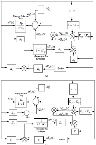
The transfer function block diagrams of the isolated wind-diesel power system conFigureurations for reactive power control at constant slip operation of the induction generator is shown in Figure 2. The details of all constants in equation (3) to (7) are given in the Appendix. The constant K3 is replaced by K3 1 , and K3 2 in the case of
136
Figure 2. Transfer function block diagrams for (a) isolated wind-diesel power system (b) wind-diesel-micro-hydro- power systemat constant slip operation (A: SVC, B: STATCOM)
Simulation Results
The wind-diesel system and wind-diesel-microhydro system has been simulated by using the system data as given in the Appendix. The gains KP and KI of the PI controllers of SVC and STATCOM have been optimized using
integral square error (ISE) criterion. The optimum values obtained for the wind-diesel system are KP = 233, KI =10312
for SVC controller and K P=35,KI=5238 for STATCOM controller and the values for the wind-diesel-microhydroare KP
= 250 and KI = 9642 for SVC controller and KP = 40 and KI = 5972 for STATCOM controller. The gains have been
137
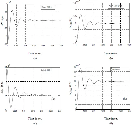
voltage. But the reactive power required by the load is suppliedby the SVC under steady state conditions as shown in Figure 3 (d). It has been observed that the oscillations following the disturbance settle down in approximately 0.0225 seconds. Similarly, the transient responses for realistic disturbance in reactive power load for wind-diesel system with STATCOM are shown in Figure 4. Again it has been observed that the increase in reactive power load is supplied by the STATCOM under steady state conditions. Comparing Figure 3 and Figure 4, it has been observed that peak deviations in the system voltage are less in case of STATCOM than that of SVC. It has also been observed that the settling time of oscillations following the disturbance is approximately 0.01 seconds which is considerably less that of SVC.Figure 3. Simulation results: Transient responses of the wind-diesel system with SVC for realistic disturbances in reactive power load showing time vs. (a) ΔV , (b) IG ΔQ , (c) SG ΔQ , and (d) com
CONCLUSION
138
ACKNOWLEDGEMENTThis work was significantly supported by the of Abadan Oil Refining Co.Iran. The authors are really indebted to the technical section manager of this Co. for his supportive character and patient.
REFERENCES
[1] Ray Hunter, George Elliot, ‘Wind-Diesel Systems, A Guide to the Technology and its Implementation,’ (Cambridge University Press, 1994).
[2] H. Nacfaire, ‘Wind-Diesel and Wind Autonomous Energy Systems’, in (ed.), (Elsevier Applied Science, London, 1989).
[3] N. G. Hingorani , L. Gyugyi, ‘Understanding FACTs: Concepts and technology of Flexible AC Transmission Systems’, (IEEE
Power Eng. Soc., New York, 2000).
[4] A. A. F. A1-Ademi, ‘Load-Frequency Control of Stand-Alone Hybrid Power Systems Based on Renewable Energy Sources’, Ph. D Thesis, Centre for Energy Studies, Indian Institute of Technology, Delhi (India), July 1996.
[5] R. C. Bansal, T. S. Bhatti, and D. P. Kothari, ‘A bibliographical survey on induction generators for application of non-conventional energy systems’, IEEE Trans. Energy Convers., 18(2003)3, pp. 433–439.
[6] K. Tandon, S. S Murthy, and G. J. Berg, ‘Steady State Analysis of Capacitors Excited Induction Generators’, IEEE Transactions on Power Apparatus and Systems, 103 (1984)3.
[7] S. S. Murthy, O. P. Malik, and A. K. Tandon, ‘Analysis of Self-Excited Induction Generator’, IEE Proceedings, 129 (1982)6.
[8] B. T. Ooi, R. A. David, “Induction Generator/Synchronous Condenser System for Wind Turbine Power”, Proceeding of IEE,
Vol. 126. No. 1, January 1979.
[9] M. A. Elsharkawic, S. S. Venkata, T. J. Williams, and N. G. Butlar, “An adaptive power factor controller for Three Phase Induction Generator”, IEEE Transaction on Power Apparatus and Systems, Vol. PAS-104, No. 7, July 1985.
[10] S. E. Haque, N. H. Malik, and W. Shepherd, “Operation of a Fixed Capacitor Thyristor Controlled Reactor (FC-TCR) Power
Factor Compensator”, IEEE Transaction on Power Apparatus and Systems, Vol. PAS-104, No. 6, July 1985.
[11] E. Hammad, “Analysis of Power System Stability enhancement by Static VAR Compensators”, IEEE Transactions on Power
System, Vol. PWRS-1, No. 4, November 1986.
[12] R. C. Bansal, “Automatic Reactive Power Control of Autonomous Hybrid Power System”, Ph.D. Thesis, Centre for Energy Studies, Indian Institute of Technology, Delhi, December 2002.
[13] Bhim Singh, S. S. Murthy, and Sushma Gupta, “Analysis and Design of STATCOMbased voltage regulator for self-excited induction generators,” IEEE Transactions On Energy Conversion, Vol. 19, No.4, 2004, pp.783-790.
[14] B. Singh, and L. B. Shilpakar, “Analysis of a novel solid state voltage regulator for a selfexcited induction generator,” Proc. Inst. Elect. Eng.,Gen., Transm. Dist. Vol. 145, No.6, pp. 647-655, 1998.
[15] E.G. Marra, and J. A. Pomilio, “Self-excited induction generator controlled by a VSPWM converter providing high power-factor current to a single-phase grid,” Proc. Industrial Electronics Society Conf, pp. 703-708, 1998.
[16] S. C. Kuo, and L. Wang, “Analysis of voltage control for a self-excited induction generator using a current-controlled voltage source inverter (CC-VSI),” Proc. Inst. Elect Eng., Gen., Transm. Distrib, Vol.148, No.5, pp. 431–438, 2001.
[17] E. Larsen, N. Miller, S. Nilsson, and S. Lindgren, “Benefits of GTO-based compensation systems for electric utility applications,” IEEE Trans. Power Delivery, Vol.7, 1992; pp.2056–2063.