University of New Hampshire
University of New Hampshire Scholars' Repository
Applied Engineering and Sciences Scholarship Applied Engineering and Sciences
8-22-1985
A Supersonic Fan Equipped Variable Cycle Engine
for a Mach 2.7 Supersonic Transport
Theodore S. Tavares
University of New Hampshire, Manchester, [email protected]
Follow this and additional works at:https://scholars.unh.edu/unhmcis_facpub
Recommended Citation
^4/>*>?/
GAS TURBINE LABORATORY
DEPARTMENT OF AERONAUTICS AND ASTRONAUTICS MASSACHUSETTS INSTITUTE OF TECHNOLOGY
CAMBRIDGE, MA 02139
A FINAL REPORT ON
NASA GRANT NAG-3-697
entitled
A SUPERSONIC FAN EQUIPPED VARIABLE CYCLE ENGINE FOR A MACH 2.7 SUPERSONIC TRANSPORT
by
T. S. Tavares
prepared for
NASA Lewis Research Center Cleveland, OH 44135
( N A S A - C B - 1 7 7 1 4 1 ) A S D P E B S C N I C F A N E Q U I P P E D N 8 6 - 2 8 9 4 6 V A R I A B L E CYCLE E N G I N E . J O B A M A C H 2 . ?
SDPEESONIC T B A N S P O B T Final R e p o r t
(Massachusetts Inst. of T e c h . ) 107 p Unclas CSCL 21E G3/07 43461
August 22, 1985
A SUPERSONIC FAN EQUIPPED VARIABLE CYCLE ENGINE FOR A HACK 2.7 SUPERSONIC TRANSPORT
by
A SUPERSONIC FAN EQUIPPED VARIABLE CYCLE ENGINE FOR A MACH 2.7 SUPERSONIC TRANSPORT
by
THEODORE SEAN TAVARES
ABSTRACT
A design stud/ was carried out to evaluate the concept of a variable cycle turbofan engine with an axially supersonic fan stage as powerplant for a Mach 2.7 supersonic transport. The study comprises two parts; a propulsion system study and a design of blade cascades for'the fan stage.
In performing the system study, quantitative cycle analysis was used to assess the effects of the fan inlet and blading efficiencies on engine performance. Thrust levels predicted by cycle analysis are shown to match the thrust requirements of a representative aircraft. Fan inlet geometry is discussed and it is shown that a fixed geometry conical spike will provide sufficient airflow throughout the operating regime.
The supersonic fan considered in this study consists of a single stage comprising a rotor and stator. The concept is similar in principle to a supersonic compressor, but differs by having a stator which removes swirl from the flow without producing a net rise in static pressure.
In the chapter on blading design, operating conditions peculiar to the axially supersonic fan are discussed. Geometry of rotor and stator cascades are presented which utilize a supersonic vortex flow distribution. Results of a 2-D CFD flow analysis of these cascades are presented. A sinple estimate of passage losses was made using empirical methods.
TABLE OF IXUl'tNTS
Abstract. 3
Table of Contents 4
Lost of Figures and Tables 6
1. Introduction. 8
1.1 Background 8
1.2 Description of Concept 10
2. Propulsion System Study 11
2.1 Mission Profile and Airframe Thrust Requirements 16
2.1.1 Mission Profile .... 16
2.1.2 Airframe Thrust Requirements 18
2.2 Cycle Analysis 20
2.2.1 Effect of Diffuser Pressure Ratio on Specific
Impulse at Design Point 21
2.2.2 Improvement in Specific Impulse Offered by
Increase in Diffuser Pressure Recovery in Supersonic Fan for Various Core Pressure Recoveries. 24
2.2.3 Sizing Engines for 650,000 Ib. TOGW SST and Comparison with Conventional Power Plants 27
2.2.4 Optimizing Bypass Ratio for Best Specific Impulse at
Mach 2.7 Cruise 30
2.2.5 Effect of Fan Efficiency on Specific Impulse at Mach 2.7 Cruise 32
2.2.6 Effect of Core Conpressor Efficiency on Specific Impulse at Mach 2.7 33
2.2.7 Matching of Superflow Engine to Thrust Requirements
3.1 Background 50 3.2 Description of Concept and. Candidate Fan Design 52 3.3 Approach to Design and Design Goals 58 3.4 Fan Aerodynamics 60 3.4.1 Discussion of Steady Flow at the Entrance of a
Cascade for Supersonic Axial Velocity 60 3.4.2 Flow Angle Restrictions on an Axially Supersonic
Cascade with Thickness 65 3.4.3 The Importance of Wave Interaction in Blades with
Large Turning 70 3.4.4 The Supersonic Vortex Blade 72 3.5 Design Tools 78 3.5.1 Analytical Design Program for Supersonic Vortex
Blades .78 3.5.2 2-D Euler Flow Analysis Code ..79 3.6 Discussion of Fan Cascades • 80 3.6.1 Fan Cascades at Design Point 80 3.6.2 Estimation of Passage Losses 86 3.6.3 Fan Rotor Cascade with Flow Misalignment 90 3.6.4 Variation of Mach Number at Rotor Design
Flow Angle 95 3.7 Summary of Work on Blading Design and Recommendations
for Future Work ...' • 99 4. Conclusion. 101 References 102
/
LIST OF FIGURES
Figure 1.1 Schematic Drawing of Variable Bypass Supersonic
Throughflow Turbo fan. 11
Figure 2.1 Mach Number - Altitude Profile of Baseline Mach 2.7 SST Mission 17
Figure 2.2 Thrust Requirements for Baseline Mach 2.7 SST 19
Figure 2.3 Variation of Specific Inpulse with Diffuser
Pressure Ratio for Conventional Bypass Engine...23
Figure 2.4 Variation of Specific Inpulse of Supersonic Fan Engine and Conventional Turtofan with Diffuser Pressure
Ratio 25
Figure 2.5 Approximate Size Comparison Between Superflow
Turbofan and a Conventional Turbojet 28
Figure 2.6 Effect of Bypass Ratio on Specific Inpulse of
Supersonic Fan Engine 31
Figure 2.7 Effect of Fan Polytropic Efficiency on Specific
Inpulse at Mach 2.7 Cruise 34
Figure 2.8 Effect of Core Ccnpressor Polytropic Efficiency
on Specific Inpulse at Mach 2.7 Cruise 34
Figure 2.9 Thrust of Superflow Engine Ccnpared to Thrust
Requirement for Baseline Mach 2.7 SST 37
Figure 2.10 Dimensions of 16 Degree Conical Spike Inlet 41
Figure 2.11 Capture Schedule of 16 Degree Conical Spike Inlet Ccnpared to Capture Schedule Required to Meet Thrust Constraint 42
Figure 2.12 Variation of Spike Shock Angle with Flight Mach
Nunber 43
Figure 3.1 Development of Velocity Diagram for a Rotor-stator
Fan Stage 48
Figure 3.2 Cascade Notation 49
Figure 3.3 Velocity Diagram at Mid-blade Radial Station
Figure 3.6 Flow in Axially Supersonic Cascade with Straight
Straight Entrance Region 66 Figure 3.7 Geometry of Supersonic Vortex Type Blade
Sections 73 Figure 3.8 Surface Mach Number Variation for Typical Blade
Section at Design Point 74 Figure 3.9 Characteristic Network Within Blade Passage at
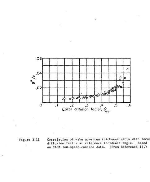
Design Point 76 Figure 3.10 Flow Through Fan Cascades at Design Point 82 Figure 3.11 Correlation of Wake Momentum Thickness Ratio
with Local Diffusion Factor at Reference
Incidence Angle 88 Figure 3.12 Effect of Incidence Angle on Flow in Rotor
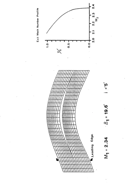
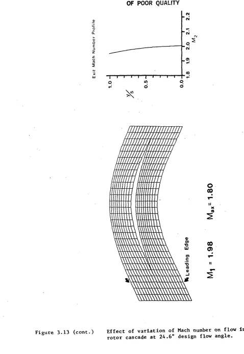
Cascade with Axial Mach Number 2.2 91 Figure 3.13 Effect of Variation of Mach Number on Flow in
Rotor Cascade at 24.6 Degree Design Flow Angle 96
TABLES
Table 1 Characteristics of the Standard Atmosphere at
Selected Altitudes in the Mission Profile 17 Table 2 Schedule of Fan and Compressor Pressure Ratios,
Bypass Ratio, and Turbine Inlet Temperature for Superflow Engine During Acceleration and
1. INTRODUCTION
A design study was performed on the concept of a turbofan engine for a Mach 2.7 Supersonic Transport which eitploys a fan stage designed to operate with a supersonic axial component of the flow at the fan face. The study conprises two parts. Chapter 2 reports results of a system study, the nain objective of which was to assess the effects of efficiency of the fan stage and its inlet on engine cycle performance and to identify characteristics of a suitable fan inlet. Chapter 3 presents candidate fan geometries, discusses operating conditions unique to such a fan, and presents results of a computational flow analysis of the blading.
1.1 BACKGROUND
Since 1972 NASA has sponsored studies to identify propulsion concepts suitable for long range supersonic cruise aircraft. These studies considered a number of conventional and variable cycle concepts. One alternative, the variable cycle engine with supersonic throughflow fan was proposed by Dr. Antonio Ferri and studied by Advanced Technology laboratories (Ref. 1). Further work on the concept was carried out by investigators at NASA-Lewis (Ref. 2). The results of these studies showed that these so-called superflow engines could provide substantial improvement in the mission capabilities of aircraft with long range supersonic cruise requirements.
engines more conventional in concept, the range capability of a baseline supersonic transport was increased by about 20 percent or 1000 nautical miles when powered by the superflow engine. The specific fuel consunption of the superflow engines were judged to be on the order of 12 percent lower. This was due in large part to lower inlet and nacelle losses for the superflow engine and more versatility in cycle variations.
Estimates of weight suggest a 30 percent reduction in installed weight for the superflow engine. For the more conventional concept engines, the inlet, nozzles, and nacelle make up about 50 percent of the propulsion system weight. The inlet systems for the superflow engines were estimated to be about 50 percent lighter than that of more conventional turbofans and additional weight savings result in that the superflow engine uses a single stage fan while the reference turbofan requires three stages.
Very little work has been performed on supersonic compressors or fans with supersonic axial velocity. The analysis of supersonic fan blading performed by Trucco in Reference 1 addresses the unique operational differences between the axially supersonic fan and older supersonic compressor concepts and predicts high efficiency for a supersonic fan. Some experimental work on an axially supersonic rotor was performed by Breugelmans
1.2 DESCRIPTION OF CONCEPT
The supersonic fan discussed in this report is variously referred to as a supersonic throughflow or super flow fan. It is designed to be operated with the axial component of the flow at the fan face supersonic, and supersonic flow is naintained throughout the rotor and stator. At flight conditions where supersonic flow cannot be naintained at the fan face, the flow at this location is choked. Thus this stage always operates with the axial component of the flow at least sonic.
This type of fan is distinguished from others which may have supersonic relative flow over part of the fan, such as the transonic fans which operate with subsonic axial Mach numbers throughout, but in which the flow relative to the blades at the outer radii is supersonic. Other rotors referred to as being supersonic, throughout, but in which the axial component of the flow is subsonic should not be confused with that referred to in this study.
The variable bypass engine is shown schematically in Figure 1.1. Since the fan can accept axially supersonic flow, a simple spike inlet, providing only minimal diffusion can be used. The flow leaving the fan stage is split into tvo streams, one of which enters the core of the engine. The other stream enters the fan nozzle. The flow leaving the fan is always supersonic, and variable bypass features can be attained by movement of the flow splitter lip.
Figure 1.1 Schematic Drawing of Variable Bypass Supersonic Throughflow Turbofan
the flow to subsonic conditions, as required by the conventional (i.e. subsonic) gas generator. The fan exhaust nozzle has variable geometry to permit optimum expansion throughout the flight envelope.
The superflow fan selected for the present study has a design airflow of 1520 Ib/sec at sea level static conditions. Its inlet is a conical spike, with a half angle of 16 degrees, and the system study performed herein suggests that it may be of fixed geometry and still provide adequate airflow throughout the flight envelope. Only slight diffusion of the bypass flow is carried out, from a free stream Mach number of 2.7 to Mach 2.2 at the fan face.
The supersonic fan is a single stage rotor-stater combination which generates thrust by increasing the velocity of the incoming flow without a static pressure rise across the stage. This implies that the Mach number at the fan exit is always higher than at the entrance, and hence always supersonic. This feature eliminates the need for a convergent-divergent section in the fan nozzle duct. The area of the fan nozzle is variable to permit expansion to ambient pressure.
range supersonic aircraft. A tJ*o spool turbine is utilised allowing some degree of independence between fan and core compressor to facilitate variable cycle features. The core flow exhaust nozzle has variable exit area for optiixum expansion ureter a variety of operating conditions.
2. PROPULSION SYSTEM STUDY
One of the primary goals of the project was to work on the aerodynamic design of an axially supersonic fan stage. However, before proceeding with this task, it was felt prudent to perform a system study and compare expected engine performance with the requirements of a representative air frame. This would give some perspective as to the operational requirements of the fan.
The system study consists of two parts. A quantative cycle analysis was performed in which emphasis was placed on the effects of fan, diffuser, and core compressor efficiencies on engine performance. The fan inlet geometry was studied. The capture schedule of a conical spike inlet was compared to the capture schedule needed to meet airframe thrust constraints.
7T«| Pressure ratio in diffusing from free stream to core compressor
fid Pressure ratio in diffusing from free stream to fan face
flfc Pressure ratio across burner
fo Pressure ratio across fan nozzle
TTn Pressure ratio across core nozzle
T£b Burner efficiency
6C Polytropic efficiency in. compression of core flow from
diffuser exit to compressor exit
£c Polytropic efficiency of fan
€t Polytropic efficiency of turbine
f£ Compression ratio of core flew
T£ Compression ratio of fan flew
"Ifcij Turbine inlet temperature
OL> Bypass ratio
F Thrust
Deo Ambient pressure
Xs Specific impulse
Flight Mach number
.Flow area at fan face
Swept area of fan cowl
Inlet capture streamtube area
2.1 MISSION PROFILE AND AIRFRAME THRUST REQUIREMENTS
2.1.1 MISSION PROFILE
The nominal mission studied was a Mach 2.7 cruise at 65,000
ft. A U.S. Standard Atmosphere was assumed. The cliirb and
acceleration path used in this study is shown in terms of
Altitude and Mach number in Figure 2.1. The relevant atmospheric
70
60
50
-A l t i t u d e 40 (thous. f t . )
30
20
10
-0.0
Altitude vs. Mach Number
s.s. cruise
1.0
2.0 3.0Figure 2.1
Flight Mach Number, M^
Mach Number-Altitude Profile of Baseline Mach 2.7 SST Mission
Flight Mach No. 0.00-0.30 0.60 0.95 1.60 2.20 2.70 Altitude (ft) 0 10,000 30,000 40,000 50,000 65,000 Pressure
(lb/ft2)
2116.2 1455.1 627.9 334.8 243.2 118.7 Temp (°R) 518.4 479.2 411.4 392.4 392.4 392.4 Speed of Sound (ft/sec) 1116.2 1077.1 994.3 ' 971.2 971.2 971.2
Table 1. Characteristics of the Standard Atmosphere at Selected Altitudes in the Mission Profile
2.1.2 AIRFRAME THRUST REQUIREMENTS
The Baseline Aircraft is a 650,000 Ib. TOO* SST fitted with four engines. Briefly the Airplane's Thrust requirements are as follows:
1. Minimum ratio of Thrust/T.O.G.W. 0.28 at Mach 0.30
2. Thrust Margin during Accereration: Thrust/Drag >1.2 at all points during climb and acceleration.
The numerical values of these constraints for the baseline
150
120
-
906 0
30
-A i r c r a f t Thrust Requirement for Baseline Mach 2.7 S.S.T.
.S. Cruise Requirement
Acceleration Requirement
Thrust
TOGW C o n s t r a i n t
OT-T
0.0 0.5 1.0 1.5 2.0 2.5 3.0
Flight Mach Number, M<
Figure 2.2 Thrust Requirement for Baseline Mach 2.7 SST _
2.2 CYCXZ ANALYSIS
The quantitative or non-ideal cycle analysis was carried out according to standard methods outlined in References 3 and 4. A FORTRAN program was developed to carry out the numerical conputation. A sunrnary of the methods used and a listing of the computer program are presented in Appendix A.
2.2.1 EFFECT OF DIFFUSER PRESSURE RATIO ON SPECIFIC IMPULSE AT
DESIQJ POINT
It is very inportant to extract maximum efficiency from the fan diffuser if a bypass engine is to be used. For engines which operate at Mach numbers substantially greater than 1, diffuser total pressure losses due to shocks can be quite significant. For example, at Mach 2.7, a normal shock produces a pressure recovery of 0.42. Since the total pressure rise across a fan stage is significantly lower than that across a fan stage is significantly lower than that across the core compressor, it is to be expected that performance of a bypass engine can be severly impaired by poor diffuser performance.
A study was therefore performed to assess the effects of diffuser performance on the specific impulse of a bypass engine which uses the same diffuser for both core and bypass flow. (i.e. this might represent a turbofan with conventional axially subsonic fan. )
This was carried out for bypass ratios of 0, 1, and 2. The gas generator efficiencies and pressure ratios was the same for all bypass ratios, as were fan stage component ef f ieiencies . The flight condition modeled was cruise at Mach 2.7.
Particulars are as follows:
Engine Parameters: T£*/i6 .1^-1.6
/Ib/sec/lb)
38
36
34
3 2
-
3028
26
2 4
-Variation of Specific Impulse with
Diffuser Pressure Recovery
22
.65 .70 .75
—i 1 1 T
—T-.80 .85 .90 .95 1.00
Figure 2.3 Variation of Specific Inpulse with Diffuser Pressure Ratio for Conventional Bypass Engine
2.2.2 IMPROVEMENT IN SPECIFIC IMPULSE OFFERED BY INCREASE IN
DIFFUSER PRESSURE RECOVERY IN SUPERSONIC FAN FOR VARIOUS
CORE PRESSURE RECOVERIES.
As shown in the previous section, the total pressure ratio in the diffuser can have a significant effect on engine performance. If instead of a conventional subsonic turbofan, the engine is fitted with a fan which can accept supersonic axial Mach numbers, less diffusion is required for the bypass flow. Presumably, this would reduce diffuser losses and lead to an improvement in specific impulse.
For this analysis, it is assumed that only a small amount of diffusion will take place in front of the fan and that the pressure recovery factor is 0.97. This figure is consistent with the inlet geometry discussed in Section 2.3.
Specific Impulse vs. Total Pressure Recovery of Core Inlet
(lb/sec/lb)
37
3 6
35
3 4
33
32
31
-
302 9
-28
TTd =.97
'= rr
d.65 .70 .75 .80 .85 .90 .95 1.00
Core Dlffuser Pressure Recovery, 7T,j
Figure 2.4 Variation of Specific Inpulse of Supersonic Fan Engine and Conventional Turbofan with Diffuser Pressure Ratio
2.2.3 SIZING ENGINES FOR 650,000 Ib. TOGW SST AND COMPARISON WITH CONVENTIONAL POWER PLANTS
In sizing the engine, the two chief constraints considered were providing sufficient airflow at the Mach 2.7 supersonic cruise design point to provide sufficient thrust at the operating point giving best SFC, and capturing enough mass flow in the takeoff configuration to meet the thrust to weight ratio of 0.28. For the superflow engine with the specified fan pressure ratio, core compressor pressure ratio, bypass ratio, and turbine inlet temperature, the overriding constraint is the thrust to weight ratio at Mach 0.30. The superflow engine sized to meet this has a total weight flow of 1520 Ibs./sec. at sea level static conditions. The static thrust per engine is 58,400 Ibs. This engine exceeds by a fair margin the required thrust during supersonic acceleration and at Mach 2.7 cruise closely matches the thrust requirement. By comparison, a conventional turbofan with the same bypass and pressure ratios would require 702 Ib/sec at Mach 2.7 as compared to 687 Ib/sec for the superflow engine. These figures represent total airflow. A second comparison may be made with a conventional turbojet with compressor pressure ratio optimized for best S.F.C. at Mach 2.7 cruise. With a
/
compressor pressure ratio of 24.0, the turbo jet would have, a significantly larger gas generator than the fan engines with an airflow of about 670 Ib/sec.
c
.2 "o
X)
o
0) a D (0
0)
'o .a
ro c o
"c
<D
> C
o O
2.2.4 OPTIMIZING BYPASS RATIO FOR BEST SPECIFIC IMPULSE AT MACH 2.7 CRUISE
For a gas generator with given characteristics of component efficiencies, conpressor pressure ratio, turbine inlet temperature and a fan of given efficiency and pressure ratio, the bypass ratio can be varied to find the optimum bypass ratio at any flight condition. This was carried out at the Mach 2.7 cruise condition for an engine with the following characteristics :
Core: T^ = 0.87 1£- IU 1 = 3*00°*
Fan: 7&-Q.17 1£- Z.B 0.05"
The specific inpulse is plotted as a function of bypass ratio in Figure 2.6. The specific thrust and specific impulse are maximized at a bypass ratio of 1.16. The specific thrust is 1.287 per unit of core airflow and 0.592 per unit of total airflow. The value of the specific impulse is 3540 (Ib/sec/lb).
Specific Impulse vs. Bypass Ratio
'sp
(lb/sec/lb)
3550-
3500-
3450-
3400-
3350-3300 -H
3250 I I I I I i I i I I i i
0.0 0.4 0.8 1.2 1.6 2.0 2.4
Bypass Ratio.
Figure 2.6 Effect of Bypass Ratio on Specific Inpulse of Supersonic Fan Engine
2.2.5 EFFECT OF FAN EFFICIENCY ON SPECIFIC IMPULSE AT MACH 2.7
CRUISE
The effect of fan efficiency on specific impulse of the superflow engine at Mach 2.7 was carried out by variation of the polytropic exponent for the fan stage. As a comparison, the variation in performance is compared in Figure 2.7 with the performance of a turbojet using the same gas generator. The component efficiencies for these engines are as follows:
Turbojet: ft«0.87lC-/U -"ft,*3lOO°R ^=0.98 ft«0 11
ec-o.85* £
t
-o.io K^
Supersonic Fan:
fid = 0.87 1C-/U JZti'3100?*.- lfcO.^8 ft,- 0.11
ec-o.65" et- 0.10 K^
The principal result of this calculation is that if the fan polytropic efficiency falls below .68 or so, the advantage of a bypass fan is outweighed by the reduced efficiency of the rotor.
2.2.6 EFFECT OF CORE COMPRESSOR EFFICIENCY ON SPECIFIC IMPULSE AT MACH 2.7
The effect of core conpressor efficiency on the specific inpulse of the superflow engine at Mach 2.7 cruise was carried out by variation of the polytropic exponent for the conpressor. The effect of this value on specific inpulse at the design point is plotted in Figure 2.8. The conponent efficiencies of the engine are as follows:
111- 0.87 T&'»0.17
ir
b
-o.«ie
, - 2 SP
flb/sec/lb)
383 7 36 35 34 33 32 31 -30
.65
Figure 2.7
Specific Impulse vs. Fan Polytropic Efficiency
.70
superflow turbofan
.75 .80 .85 .90 .95 1.00
Fan Polytropic Efficiency , 6C
E f f e c t of Fan Polytropic Efficiency on Specific Impulse at Mach 2.7 Cruise
,-2
(ib/sec/ltA
2.2.7 MATCHING OF SUPERFLOW ENGINE TO THRUST REQUIREMENTS THROUGHOUT
FLIGHT ENVELOPE
A quantitative cycle analysis of the superflow engine was performed over the range of mission flight Mach numbers and the
results compared with the airframe thrust requirement. The
component efficiencies and characteristics used for the analysis are as follows:
76-0.67
The fan and conpressor pressure ratios, bypass ratio, and turbine inlet temperature follow the schedule outlined in Reference 1. These quantities are tabulated in Table 2. The mass flow schedule corresponds to choked conditions in front of the fan for subsonic Mach numbers and that dictated from inlet conditions for supersonic Mach nuntoers. The inlet used is described in Section 2.3. The specific thrust of the engine compared to the thrust requirement is plotted in Figure 2.9.
Acceleration
S. S. Cruise
1
1
'////////////
/
1
+
MOO 0.00 0.30 0.60 0.95 1.60 2.20 2.70 2.707T
C 24.0 24.0 31.8 32.7 30.5 21.7 14.6 14.6TTc
3.0 3.0 3.7 3.8 3.5 3.1 2.8 2.8ex.
1.80 1.81 1.56 1.50 1.55 1.36 1.16 1.16Tt4(°R)
2550 2550 3250 3060 3400 3400 3400 3200
150
120
-90 H
6030
-0
0.0
Thrust of Superflow Engine vs.
A i r c r a f t Thrust Requirement
Thrust
TOGW Constraint
.S. Cruise Requirement
Acceleration Requirement
i-cycle calc. points
' I I r 0.5 1.0 1.5 2.0
Flight Mach Number, t
2.5 3.0"
Figure 2.9 Thrust of Superflow Engine Compared to Thrust Requirement for Baseline Mach 2.7 SST
2.3 INLET DESIGN
In the overall assessment of the supersonic through flow engine, the technical feasibility of an inlet with the specified mass flow schedule and pressure recovery is an important consideration. As shown in the cycle analysis, the performance advantage offered by the bypass engine is quite sensitive to the pressure recovery of the fan inlet.
Secondly, for an aircraft flying at super sonic speeds with the inlet started, the fan can exert no upstream influence and hence the mass flow to the engine is dictated by the fan inlet. For the supersonic fan engine at subsonic speeds, it has been proposed to operate with the flow choked at the fan face. This dictates an inlet with the minimum flow area at the fan face, at least while flying subsonically.
It has been found that a fixed geometry inlet with straight conical spike provides the required mass flow schedule throughout the flight envelope with an acceptable level of pressure recovery. For the purpose of the design study, the calculated performance of this type of inlet sets a baseline for diffuser performance from a standpoint of shock losses and capture that can be expected. Potential advantages and problem areas of more sophisticated inlet designs can be compared with it.
to make structurally robust. Secondly, at zero degrees angle of attack, the cone boundary layer is not subjected to a pressure gradient, except perhaps for a snail pressure rise inside the fan cowl. So called isentropic coipression inlets which achieve pressure rise by a nearly continuous pressure rise on the surface of the spike can in principle reduce shock losses, but these are prone to separation problems. Angle of attack changes can lead to inlet distortion problems and an increase of the pressure gradient. Conversely conical spike inlets can be made quite insensitive to angle of attack.
Choked flow at the fan face at subsonic operation conditions sets the flow area required at the fan face. At the supersonic design point, the inlet is configured so that the conical shock originating at the tip of the spike intersects the cowl lip in the interest of minimizing wave drag at this flight condition. Additionally, it is desired to make the cone angle as large as possible to make the spike as short as possible for weight and structural reasons. However, there are limits to the cone angle which can be used for the following reasons:
a)Shock loss from the conical bow shock increases with cone angle. .
b)Requirement to keep shock attached to cone down to relatively low Mach number.
c) Necessity to fair the cone to the rotor with the desired
hub to tip radius ratio. It is desired to make the cane surface Mach number marginally above that which will prevail at the fan face.
d)Necessity to limit "supersonic spill" in off design flight conditions to meet mass flow constraint.
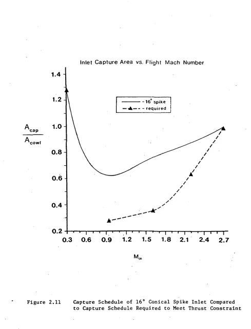
For purposes of the design study, it has been assumed that the inlet meets the air at the flight Mach number of 2.7. (This may be modified by engine mounting locations in which the inlets are placed aerodynaniically in the proximity of the wing or other components.) A cone half angle of 16 degrees and an annulus area, of 30.7 ft ^ meets the outlined constraints for an engine with a sea level static mass flow of 1520 Ib/sec. A dimensioned sketch of the inlet is shown in Figure 2.10 and Figure 2.11 illustrates the capture schedule of this inlet compared to that required to meet minimum mass flow requirments. At the design point/ the pressure ratio of the conical shock is 0.99 leaving a 2 % margin to meet the target pressure recovery of 0.97. The shock angle variation at off design conditions are shown in Figure 2.12.
7.9 ft
4.3ft 4.7ft
A
f f= 30.7ft'
Inlet Capture Area vs. Flight Mach Number
cap Acowl
1.4-
1.2-1.0
0.8-0.6
0.4
0.2
0.3 0.6 0.9 1.2 1.5 1.8 2.1 2.4 2.7
27.5 A = 48.8ft2
M-2.7
32.5
A. = 42.6M3
= 2.2
42.5 : 37.7ft'
M-1.6
2.4 SUMMARY OF SYSTEM STUDY
The system study performed herein serves to show the relative merits of employing a bypass fan in an engine designed to operate at high Mach number. The diffuser pressure recoveries tend to figure significantly in the balance of whether the bypass engine offers an inprovement in uninstalled specific impulse over the turbojet or more conventional bypass engines. At high Mach numbers, the pressure recoveries of supersonic-subsonic diffusers tend to deteriorate and the development of a fan which could accept axially supersonic flow is a unique solution to this problem.
However, this is only part of the story. As pointed out in Chapter 1, part of the advantage of the superflcw engine lies in lower installation losses, due to smaller, less complex, fan cowls and nacelles. These factors were not taken into account in this investigation, and all cycle analysis results represent uninstalled performance figures. If the concept is pursued further and a detailed geometry defined, the installation losses must be seriously considered, both from the standpoint of cowl and nacelle drag, and that of interference between engine and air frame. Otherwise, the performance improvement offered by the superflow engine concept may not be realized.
3. BIADING DESIGN FOR SUPERSONIC THROUGHFD3W FAN
SYMBOLS
Ttie following syntols are used in this chapter: A flow area
c chord length
D,6t local diffusion factor (based on local velocities)
i incidence angle, angle between intet-air direction and tangent to blade mean canberline at leading edge in degrees
M Mach nunfcer
pt total or stagnation pressure p static pressure
s blade spacing v air velocity
z coordinate along axis
.S air angle, angle between velocity vector and axial direction in degrees
6 leading edge half angle
K. blade angle, angle between tangent to blade mean camber line and axial direction in degrees
ID blade camber angle, difference between blade angles at blade leading and trailing edges, K.,-^ degrees
5D total-pressure loss coefficient
Q flow deflection angle (in reference to shock waves forming) P shock wave angle relative to incident flow
6 solidity
V Prandtl-Meyer angle
The nomenclature and syntools for designating velocity triangles as used in this report for a fan stage made up of a rotor and stator are represented in Figure 3.1. The notation and syntools describing cascade geometry and flow angles are shown in Figure 3.2.
b)
O)r
c)
d)
Rotor
v
d'
Md
Stator
Mean
camber
line
I Measuring
plane \
Axial direction, z
3.1 BACKGROUND
Very little in the way of analytical predictions or experimental data exists on turbomachinery with supersonic axial velocity, with work on blading applicable to a supersonic fan being almost non-existent.
Seme work has been performed since the 1950's in the area of supersonic compressors. Most of this pertained to machines with subsonic axial velocities, but supersonic relative velocities, and these can be separated into two types, namely shock in rotor and shock in stator compressors. The shock in rotor variety, as the name implies, produces transition from supersonic to subsonic relative velocities in the rotor by means of shocks within the rotor passage. This transition is accompanied by a substantial static pressure rise and the flow enters the stator with subsonic velocity. The shock in stator compressor turns the flow in the rotor while maintaining supersonic relative velocity and the diffusion to subsonic velocity occurs in the stator. Very few experimental results exist for this type, most experimental work having been performed on stages of the former type. (See Refs. 6
& 7.)
The results of these experiments were for the most part disappointing with measured stage efficiencies being lower than predicted. However, tests performed by Daimler-Benz (1968) on impulse type rotors with downstream stator removed have shown
More recently, BreugeLnans (1975) published results of experiments on an isolated rotor designed to accept flow with an axially supersonic flow at the face of the rotor. This rotor employed blades with 25 degrees of camber at the mid-blade radial station and had a hub to tip ratio of 0.75. At 100% design rotor speed the axial Mach number was intended to be 1.5 with a tip tangential Mach number of 2.0 based on inlet total conditions. This rotor was never tested beyond 90% of design speed due to mechanical failure. However, at this operating point the axial Mach number was 1.5 and the relative Mach number at the tip was 2.4. This is the sole example of experiments performed on an axially supersonic rotor known to this author. (See Refs. 11 & 12.)
Breugelmans' rotor design was hot pursued for this study as its axial Mach number was too low and its rotational speed too high for the fan rotor of the super flew engine. It was proposed for this investigation to perform only minimal diffusion of the free stream flow, from Mach 2.7 to Mach 2.2 at the fan face. Secondly, the design tangential Mach number of the Breugelmans rotor translates to a physical speed of about 3000 ft./sec. for the superflow fan at its design point. This was felt to be too high from a standpoint of mechanical stress.
3.2 DESCRIPTION OF CCNCEPT AND CANDIDATE FAN DESIQJ
The supersonic fan considered in this study consists of a single stage ccnprising a rotor and stator. The concept is similar in principle to a supersonic compressor, but it differs by having a stator which removes swirl from the flow without producing a net rise in static pressure. In the present application the goal is to create a stage with a larger velocity at the exit of the stator than at the entrance to the rotor, and thus has an exit static pressure lower than the inlet static pressure. This is possible because at supersonic flight conditions, the flow entering the fan has been decelerated by the inlet and is thus at a higher static pressure than the free stream. Therefore, it is possible to have a fan stage which permits a static pressure drop across the stage without having the pressure drop below atmospheric. Such a stage imparts lower local pressure gradients at the trailing edge of blade suction surfaces, and therefore it is expected that trailing edge separation can be more readily prevented. By keeping the flow attached and wakes small, it is expected that two major sources of losses which accounted for poor performance in many early attempts at supersonic compressors can be diminshed.
their radius.
The third type of loss takes place at the entrance of a blade row placed downstream of another. Because one row of blades is rotating with respect to another, the downstream row receives a flow which is non-uniform and is thus unsteady. The result of this unsteadiness is the generation of time varying pressure waves which absorb energy. For a supersonic stage, this is especially serious as strong shocks may form, causing substantial losses. Additionally, this unsteadiness is a source of noise. Therefore, in the design of a supersonic fan stage effort must be made to minimize the magnitude of this unsteady component.
A fan total pressure ratio of 2.8 has been specified at the supersonic cruise point at Mach 2.7. At this flight condition, the axial Mach number at the fan face is 2.2 and the chosen tip tangential Mach number is 1.26, corresponding to a physical tip speed of about 1375 ft./sec. The fan rotor diameter is 7.9 ft. A set of velocity triangles at the mid-blade radial station r/rT =0.8 is sketched in figure 3.3. A polytropic exponent of 0.85 was assumed for the stage and the turning required calculated from the Euler Turbine Equation. The impulse type rotor turns the flow about 50 degrees in rotor fixed coordinates, and about 43 degrees of turning are required in the stator to remove swirl
from the rotor exit flow.
The requirement for large amounts of turning in both rotor and stator came about from the desire to achieve the specified pressure ratio in a single stage at a reasonable rotor speed.
This places emphasis on the need for careful blade passage design to prevent large shock losses, choking of the flow, and large velocity non-uniformities at the blade exit flow. Operation of the fan stage at supersonic axial Mach numbers gives rise to unique operating conditions. These are:
1. During supersonic operation the flow condition at the fan face are set by the inlet. Therefore rotor speed must be matched to the axial flow to prevent large blade incidence angles which could cause the blade passages to unstart, resulting in large shock losses.
2.Blade surface pressure distribution is influenced to a large extent by wave interaction within the passages. This interaction must be carefully tailored to maintain fully supersonic flow and to produce uniform exit flow.
Candidate rotor and stator mid-blade passage geomtries are presented in Figure 3.4. The rotor cascade has a camber angle of 49.2 degrees and a solidity of 5.9. The blades are 3.0 % thick. The stator has a camber angle of 42.5 degrees and a solidity of 5.6. The blades are 7.4% thick.
The blade shapes were determined by the use of an analytical method which generates surfaces which produce a supersonic vortex flow given the inlet and exit Mach numbers, and the peak values of the Mach numbers on the suction and pressure surfaces. This type of cascade is discussed in more detail in Section 3.4.4.
I Surface Height
100
Z Axial Length
Rotor Cascade Coordinates
Z Axial Length
0 b 8 12 16 20 2l» 28 32 36 bo
b b '
1.8 52 56 60 6U 68 72 76 80 81. Z St Upper 0.00 1.82 3.65 5.U8 7.32 9.15 10.86 12.32 13.55 111. 57 15.lt! 16. Olt 16.36 16.36 16. oi. 15- 111 lb.57 13-55 12.32 10.86 9.15 7.32 irface He Lower 0.00 1-75 3. Ill li.97 6.1.1 7.7li 8.95 10. Oil 11.01 11.85 12.57 13-07 13-32 13.32 13-07 12.57 11-85 11.01 10. Oil 8-95 7.71. 6.1.1 ight Lower + Cap 16.87 18-62 20.28 21.81. 23-28
21. . 61
H e i g h t
100
X Axial Length Stator Cascade Coordinates
Z Axial Length 0 k 8 12 16 20 2U 28 32 36 1.0 u 1.8 52 56 60 61. 68 72 76 80 8k 88 92 96 100 I Su Upper 0.00 3.68 7.35 11.01 1U.67 18.33 22.00 25.61 28.88 31.58 33.86 35.61 36.95 37.88 38.51 38.86 39.12 39-17 39.19 39.19 39.19 39.19 39.19 39.19 39.19 39.19 rface He Lower 0.00 3.5k 6.91 10.09 13.09 15-91 18.50 20.91 23.12 25.13 26.96 28.70 30.11 31.88 32.61. 33.77 3U.65 35. k2 36.07 36.67 37.27 37. 8k 38.20 38.52 38.86 39.19 ight Lower + Gap 19.26 22.80 26.17 29.35 32.35 35.17 37.76 1.0.17 U2.38 W.39 U6.22 1.7.96 1.9.37 50.61. 51-90 53.03 53.91 51.. 68 55.33 55.93 56.53 1 57.10 57. U6 57.78 58.12 58.k5
Figure 3.A (cont.) Rotor and Stator Cascade Coordinates.
3.3 APPROACH TO DESIGN AND DESIGN GOALS
Little precedent exists for blade shapes, velocity triangles, or passage velocity distributions for a supersonic fan. Therefore, effort nust be made to gain insight into the requirements for a supersonic fan stage. The thrust of this investigation was to gain appreciation for conditions under which fan must operate, establish flow turning angles, and come up with a. design of candidate blade passages. To simplify the problem within the context of this investigation, the blade design study was confined to operation at the design point and the problem reduced to design of two dimensional cascades which would represent a candidate fan at its mid-blade radial station.
Fan turning was established by choosing fan tangential Mach number, assuming a fan stage polytropic efficiency consistent with the system study, and then establishing turning by use of the Euler Turbine Equation for the needed stage total temperature ratio.
The choice of a supersonic vortex velocity distribution within the blade passages allowed analytical calculation of blade geometries. (See References 8 & 9.)
and Mach numbers. A siirple loss analysis was performed using the
Lieblein correlation for cascade data. The following design
criteria were set for the cascade passages:
1. Wave losses due to rotor-stator interaction must be
minimized. To facilitate this rotor blade passages must be
designed to perform flow turning of the amount required for a
stage pressure ratio of 2.8 and provide uniform exit profile at
design Mach number and incidence angles. It is also important to
achieve reasonably uniform exit flow from the stater. This is to
prevent large shock and viscous mixing losses downstream of the
stator.
2. The flow diffusion factor must be low enough that flow is
expected to remain attached, and the total pressure loss
coefficient as predicted by the Lieblein method must be low
enough that cascade profile losses are consistent with
the requirement of a stage polytropic efficiency of 0.85.
3. Shocks must be minimized within the blade passages. This
is important for two reasons, the first of which is to minimize
the total pressure loss directly associated with the formation of
shocks. The second reason is to prevent excessive growth of the
wake momentum thickness due to interaction between shock waves
and blade boundary layers. Hence, in the cascades designed in
this investigation, the leading edges have been made thin and
sharp.
3.4 FAN AERODYNAMICS
Before moving on to the discussion of the blades designed in this investigation, it is useful to discuss some fundamental points. In the following sections, the operating conditions unique to an axially supersonic blade row are addressed, as are considerations for designing blades which can produce large turning, while maintaining supersonic flow throughout the passages and achieving uniform flow at the blade exit stations.
3.4.1 DISCUSSION OF STEADY FLOW AT THE ENTRANCE OF A CASCADE FOR
SUPERSONIC AXIAL VELOCITY
Consider a supersonic cascade having blades of zero thickness and without camber as shown in Figure 3.5. The incident flow is supersonic steady and has an axial component that is subsonic and of magnitude OB. For steady conditions no waves can travel upstream of the infinite cascade as explained in Reference 7. Therefore, the velocity denoted by the vector OA in front of the cascade must be parallel to the blades.
Expansion Wave
/ / / / I Compression
a. Variation of tangential velocity.
b. Variation of axial velocity.
Figure 3.5 Flow at entrance of supersonic cascade having zero thickness and camber, (from Ref. 7)
at which the axial velocity becomes sonic.
At the point where the axial velocity becomes sonic the situation changes qualitatively for the following reason: If tangential velocity is increased infinitesimally, waves of infinitesimal strength will be produced at the leading edge. However, these will be contained within the passage. Only by production of a shock of finite strength could waves be propagated upstream. Such a shock would in turn produce flow with a subsonic axial component. Suppose now, with the axial velocity sonic, that the tangential velocity is increased from AjB^to B^C.This presents a relative velocity which increases from OAj_ to OC. This produces an incidence angle between the flew and the blades. Expansion waves are ' produced on the trailing surfaces of the blades. These are contained within the passages as are the compression waves as long as the compression waves are not of sufficient strength to produce shock detachment. Thus no waves are transmitted upstream and the axial velocity is unchanged. This situation represents a steady state and it follows from this argument that the maximum axial Mach number that can be produced by increasing the tangential velocity is sonic.
Consider now a case wherein the axial velocity is varied. When the axial velocity OB is less than sonic, an increase of
situation is different if the axial component is greater than or equal to sonic.
Suppose initially, the velocity is represented by the triangle OB^C with the axial component OBjj_ . (See Fig. 3.5) A small increase takes place which increases the axial component form OB^ to OB ^ and the relative velocity is thus represented by QAZ and this time, a compression wave is produced on the trailing surface of the blade and expansion waves are generated by the leading surface. The expansion waves are of course contained within the passage. If the compression waves are sufficiently weak, (a sufficiently weak shock being one in which the axial component of the flow behind the shock is supersonic), and if the shock detachment angle is not exceeded, then the compression wave will be contained within the passage. Since there is no upstream
influence exerted by these waves, this represents a steady condition. This shows how the cascade may attain operation with supersonic axial Mach number, and that this can only be attained by change of the flow Mach number upstream.
These considerations for the infinite cascade may be extended to the superonsic rotor with the following implications: If the entrance region to the blades is straight, the velocity relative to a rotor with subsonic axial velocity is not changed in direction but tends to remain aligned with the blade suction surface. A change in tangential velocity of the rotor will produce a corresponding change in the axial velocity of the flow up until the condition of the flow becoming axially sonic. Below this point the axial velocity at the fan face is influenced by
the rotational speed of the rotor and is therefore independent of
flight conditions.
Once the axial ccmponent of the velocity has become supersonic, an increase of the rotational speed of the rotor can produce no change in the axial velocity, and the mass flow is fixed by the inlet. The fan may then operate at different mass flows and pressure ratios at the same rotational speed. This discussion may be extended to a blade with a finite leading edge thickness to consider the effects of the leading edge on the
3.4.2 FLOW ANGLE RESTRICTIONS ON AN AXIALLY SUPERSONIC CASCADE
WITH THICKNESS
Consider the entrance region of a supersonic cascade. Assume that downstream of the entrance region the blade geometry is such that fully supersonic flow is permitted. The geometry of the entrance region comprises a wedge of half angle cS which is
inclined such that the trailing surface AB is inclined at an angle .'K|4 <S from the axial direction. The.axial component of the incident flow is supersonic.
First assume that the flow is such that \Q>} z. Kt* 5 • Expansion waves form on the trailing surface but are completely contained within the passage since the axial Mach number is greater than 1. On the leading surface AC, the flow undergoes a compressive flow deflection of magnitude Q= J& - K, + <5 • *f the flow deflection is small enough that for the incident Mach number IVL the flow is below the angle which will cause shock detachment, an oblique shock contained within the passage results, and there is no upstream influence. If however the flow deflection is large enough to cause shock detachment, the flow behind the shock is subsonic and the passage unstarts.
'ax
-Cascade entrance region geometry and flow notation.
r e
Shock wave notation.
CO (J 13 co cu x: CO u o en •H 3 3 O o •H U •H . T3 5 c rj O 3 °
3 "
< -H 0) •a CO 4-1 c ai u CO %T~> -a CO 0) CX. O CJ •H C o en>-. ai Q. 3 05 T3 ai o CO cfl W o o jr 4-1 •H w ai a (0 LM l-i 3 en t>o C •H 3 O CO O -a ai u CO cfl en o o en js •H 3 CO cu o co 3 en oo c T3 co ai 3 -H o i-l O pt. UQ <f^ - <5 expansion waves form on the leading surface AC. In either case, waves from the leading surface are contained within the passage and exert no upstream influence.
Three scenarios are possible:
1. Flow deflection angle £) = K, *• <5 ~>B i is large enough to cause shock detachment and the passage unstarts in a similar fashion to the case .of a detached shock forming on the leading surface.
2. ~@ is small enough to allow an. attached oblique shock to form and the shock wave angle relatiye to the incident flow angle is such that "P < HO -J&\ • In this case the shock is contained within the passage and no waves are propagated^ upstream.
3. A third possibility exists that under certain conditions the flow deflection angle while producing an attached shock on an
isolated wedge produces flow downstream of the shock with a subsonic axial component. The associated shock angle is such
that "_p-> ^0°' /6( • In this case the shock points upstream. Clearly this is inconsistent with the condition of axially
restrictions on the range of incidence angles over which a blade row may operate in the axially supersonic condition. These restrictions are derived independently of the details of the blading geometry downstream. It should be pointed out however, that choking may occur inside the passage at incidence angles below which this may be a problem, and hence should not be taken as conservative estimates of the allowable range of blade incidence angles.
3.4.3 THE IMPORTANCE OF WAVE INTERACTION IN BLADES WITH LARGE TURNING
Since it has been proposed to incorporate blade passages in the design which are fully supersonic, it is useful to model the cascade as a series of stacked supersonic nozzles rather than airfoils. Since the flow is supersonic throughout, there can be no contnunication between suction and pressure surfaces of a single blade, (except through boundary layers but this is neglected in this inviscid analysis), yet strong interactions may be present between adjacent blades. These are indeed necessary to provide desired flow conditions. If the blades were spaced such that no interaction took place, and if the blade surfaces were shaped such that no strong shock waves were generated, the Mach nuirber of the flow on the concave surface would decrease in a Prandtl-Meyer compression. Likewise, the flow on the convex surface would increase in Mach number in a Prandtl-Meyer expansion. At the trailing edge of the blade, the flow on the concave surface would have its Prandtl-Meyer angle decreased by the value of the turning angle, while the flow along the convex surface would have its Prandtl-Meyer angle increased by the value of the turning angle. Hence in blade passages where turning is large, the velocity discontinuity at the trailing edge would be considerable.
concave surface would fall below 1 in conflict with the design requirment.
Thus, it is clear that blade passage geometry must provide for wave interaction to achieve the desired passage Mach number distribution. . However, in tailoring passage geometry, care must be taken to insure that the resulting shapes stack to form closed blades of positive thickness.
3.4.4 TOE SUPERSONIC VORTEX BIADE
The design of supersonic blade sections described herein is based on establishing a vortex flow within the blade passages, as developed in References 8 and 9. The blade so designed consists of three major parts; inlet transition arcs, circular arcs, and outlet transition sections. A representative passage is shown in Figure 3.7. The inlet transition arcs are required to convert the uniform parallel flow at the leading edges into a vortex flow. The circular arcs maintain the vortex flow field, thereby continuing flow turning. The outlet transition arcs restore the flow to parallel flow at uniform Mach number at the blade exit. Additionally, on the blade suction surfaces, straight line
sections are used to close the blade formed by the passages. A typical blade surface Mach number distribution is shown in Figure 3.8. This shows that the inlet transition section on the concave surface reduces the Mach number from its inlet value Mlf to a preselected value of the value of the pressure surface Mach number M,. Likewise, the transition arc on the convex surface increases the inlet Mach number to the specified value for the upper surface M,.. The Mach numbers remain at a constant value on the circular arc surfaces. At the outlet transition arcs, the flow on the surfaces is returned to a uniform flow at the prescribed exit Mach number M^.
AB Inlet suction surf, transition arc FG Outlet suction surf, transition arc CO Inlet pressure surf, transition arc
HI Outlet pressure surf, transition arc AF Suction surf, circular arc
CH Pressure surf, circular arc BEandGj Straight lines
Figure 3.7 Geometry of supersonic vortex type blade sections.
Surface Mach Number, M
M,
Suction Surface
M,,
Blade Outlet
Blade Inlet
M,
Pressure Surface
transition arcs, and that which is produced by the circular arcs. Since the flow is assumed to be isentropic and fully supersonic, it is convenient in this case to introduce description of the flow in terms of its Prandtl-Meyer angle.
The characteristic lines of the flow through a supersonic vortex blade passage is shown in Figure 3.9. It can be seen that the surfaces of the inlet tranistion arcs are boundaries of simple regions (i.e. no wave interaction takes place in this region.) Thus, the change in the Prandtl-Meyer angle of the flow on the passage surfaces is equal to the difference in angle between the surface and the inlet flow. The Mach number distribution in the exit transition region is identical to that in a similarly shaped inlet region in which the direction of flow has been reversed. (This is due to flow reversal properties in isentropic supersonic flow.) Hence, the turning angle required of the transition arcs is given by~^( _ Vy and^ - Vu^or ^ne upper and lower inlet tranistion arcs, and\A - Vu and \J - VL f°r ^e upper and lower exit transition arcs. Hence, it can be reasoned that the maxinum suction surface, and minirtum pressure surface Mach numbers are limited by the relations:
rvl 2. v,
-For a 2-D section, the flow exit angle and the exit Mach number have a unique relation for the given inlet Mach number and
AB inlet suction surf, transition arc CD Inlet pressure surf, transition arc CE Major expansion characteristic AE Major compression characteristic
(Circular arc
Characteristics
Vortex • — — — — Transition
flow angle. To obtain a closed blade, the exit area normal to the flow is given by the relation:
Then to satisfy the continuity equation, the inlet and exit Mach numbers are related by the isentropic one-dimensional relations for a channel of area ratio A^/A^.
As stated above, a single flow passage nay be constructed for any selection of suction and pressure surface peak Mach numbers, provided that the sum of required transition arc turning does not exceed the total turning angle desired. However, satisfying these conditions does not guarantee that closed blades will result when these passages are in cascade. There are cases where the result would be blades of negative thickness, but for most practical choices of turning angles and Mach numbers, this has not been a problem.
3.5 DESIGN TOOLS
3.5.1 ANALYTICAL DESIGN PROGRAM FOR SUPERSONIC VORTEX BLADES
A FORTRAN computer program for the design of supersonic passages based on establishing a vortex velocity distribution as outlined in Reference 9 was adapted for use on a DEC POP 11/70 oonputer. The construction of passages which produce supersonic vortex flow is discussed briefly in Section 3.4.4.
The information required for input consists of inlet flow angle, inlet and flow Mach numbers, and maximum Mach number on suction surface and minimum Mach number on pressure surface. All Mach numbers are specified in terms of their Prandtl-Meyer angles.
3.5.2 2-D EULER FLCW ANALYSIS CODE
The Euler Equation Solver enployed in this study is a conservative streamtube solution of the steady state equations. This technique was developed at MIT and is explained in detail in Reference 10. The method is similar to streamline curvature methods but uses a conservative finite volume formulation to ensure correct shock capturing. In this investigation, the supersonic solver was used which employs a space marching solution procedure which takes full advantage of the hyperbolic character of the steady state equations.
The method is quite robust and fast, (typical solution times being on the order of 10 CPU seconds on a DEC PDF 11/70 computer) making it ideally suited for design problems. For design calculations, the method has the additional advantage that flow boundary conditions can be specified in terms of blade passage geometry surface pressure distribution, or ccnfoinations thereof. Plotting software for producing streamline diagrams and Mach number contours accompanies the flow solution program.
3.6 DISCUSSION OF FAN CASCADES
3.6.1 FAN CASCADES AT DESIGN POINT
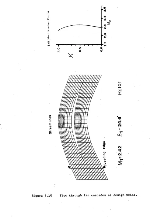
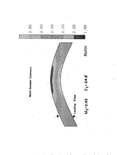
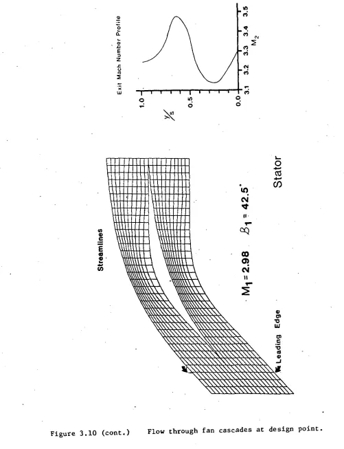
The streamline grids of the rotor and stator cascade, as
calculated by the supersonic Euler solver at the design point,
are shown in Figure 3.10. Also included are Mach number contours
and Mach number profiles of the blade exit flows. The
streamlines and Mach number contours of both rotor and stator
cascades show the flows in the passages to be shock free.
It must be pointed out that the complete absence of shocks
was obtained by generating blade geometries in which the leading
edges are infinitely thin. This is unacceptable for structural
reasons, in constructing practical blades. A refinement of these
cascade designs would be to modify them with a leading edge with
a finite wedge angle. A method for doing this is suggested in
Reference 8. It is felt that these could be incorporated without
drastic changes to the overall blade profiles, and the leading
edge compression waves could be effectively cancelled by
generating expansion waves downstream. In doing so, the
supersonic vortex flow pattern could be maintained.
In constructing blade profiles with the analytical method of
characteristics program, rotor suction and pressure surface Mach
numbers of 3.1 and 1.9 were specified. The Euler solver
calculated peak suction and pressure surface Mach numbers of 2.9
. and 1.9 showing excellent agreement with theory. The exit
profile shows excellent flow uniformity. In calculating the
numbers of 4.3 and 2.1 were specified. The peak Mach numbers calculated by the Euler solver are 3.8 and 2.2. Part of the discrepancy may lie in the fact that the analytical routine had difficulty generating a geometry with a 0.0 degree exit angle. As a result, the stator was designed by graphically joining the required inlet transition arcs with exit transition arcs desinged for a non-zero flow exit angle. This may also account
for the lack of flow uniformity (around 5% about the mean Mach number) in the stator exit Mach number profile. However, this may not be a serious problem, as long as the nonuniformity does not cause strong shocks to form in the nozzle.
«D I • N 0! £1 E 3 z o (0 5 X UJ n • •-CM in
d o6
ID «
£
(0
.
\ \ \ \ \ \ \ \ \ T O
\\\\\\\\\\
o
DC
0 cn •o UJ cn c •6 (0 ® CM II r-CM <t CMit-.
\\\\\\\\\\\\\\\\\
o 03
O CO
o O
O ooo
f\J f\) r\j r\j r\j
o «*
"o O
w O
O
E
o
CO
o
DC
CO ^•' CM
II
CM t CM ir
Figure 3.10 (cont.) Flow through fan cascades at design point.
o o
co on
o o o
o
o
on on on
c\j cvi
oj
a>w
O *rf
'o O w
S> XI £
3 Z O
Figure 3.10 (cont.) Flow through fan cascades at design point,
3.6.2 ESTIMATION OF PASSAGE LOSSES
The LdLeblein correlation of cascade data was used to
estimate passage losses at the design point. While this method was derived using low speed cascade data, limited data on fully supersonic cascades suggests applicability of the method to blading of this type at least over a range of incidence angles where shock losses are small.
LaRocca investigated 2 annular cascades incorporating 36 degrees of turning at an inlet Mach number of 2.0. One passage incorporated no static pressure rise across the blade row, while the second featured a slight static pressure drop. The solidity ranged from about 4.1 at the tip to 5.2 at the hub. For these cascades, the measured total pressure loss coefficient was about 1% higher than that predicted from correlation with the diffusion factor. A possible source of the additional loss are unaccounted for shock losses. (See Reference 14.)
For the cascade passages presented for the supersonic fan, with sharp leading edges and pressure distributions tailored to eliminate strong waves at the design point, it is expected that at the design point the Lieblein correlation is adequate for a first estimate of passage losses.
The loss calculation was carried out according to the method presented in Reference 13. First the local diffusion factor was
calculated according to:
and the mcmentum thickness ratio of the wake taken from Figure 3.11 The using the relation:
the loss coefficient was calculated.
For the rotor, the diffusion factor D(()C is 0.10 yielding a blade mcmentum thickness ratio of about 0.005. The total pressure loss coefficient of the rotor cascade is thus 0.065. The stator cascade across which there is a static pressure loss, has a very low diffusion factor of 0.02. The wake momentum thickness ratio is again on the order of 0.005 and the total pressure loss coefficient is about 0.030.
The low diffusion factors and hence relatively thin momentum thicknesses of the boundary layers of both rotor and stator cascades suggest that both boundary layers are attached at the
.06
.04
,02
0
.2 .3 .4 .5 .6Locol diffusion factor, D
design point and there is sane margin before separation is likely to occur. Suction surface boundary layers, for subsonic blading at least, remain attached up to diffusion factors of around 0.5 where the momentum thickness is seen to increase rapidly, thereby
suggesting that separation has occurred.
The adiabatic efficiency of a stage made up the rotor and stator cascades, accounting for the losses estimated above was calculated according to the formula:
-1
from Reference 3. The adiabatic efficiency predicted from this calculation is 0.94 corresponding to a polytropic exponent for the stage of about 0.95.
This is at best an incomplete analysis of losses that might be present in a fan stage made up of these cascades as three dimensional and endwall effects, and rotor-stator interaction losses have not been estimated. However, it does serve to illustrate that the cascade geometries presented allow a margin of about 0.10 for other types of losses in designing a fan stage with a polytropic efficiency of 0.85, as assumed in Chapter 2.
3.6.3 FAN ROTOR CASCADE WITH FLOW MISALIGNMENT
With the axial Mach number set at 2.2, the rotor blade incidence angle was varied in 5 degree increments. This simulates conditions at the fan face when the flight Mach nuniber is 2.7, and the rotor tangential speed is varied from that value which produces flow at zero incidence. Convergence of the Euler solver was obtained for incidence angles varying from -10 to +5 degrees. This suggests that axially supersonic flow can be maintained over a range of at least 15 degrees at this flight condition. Streamline grids and exit Mach number profiles are shown for these cases in Figure 3.12. It is believed that this represents a fairly conservative estimate of allowable incidence angles, since the supersonic flow solver fails to converge whenever a grid point is encountered where the axial component of the Mach number falls below 1. Even if axially supersonic flow breaks down, this analysis does not suggest any particular problems with operating in an axially subsonic condition. However, a transonic flow solver would be required to study this
in further detail.
As expected, shocks are observed in the passages. These are relatively weak and it is not expected that they are sources of major losses in themselves. However, as pointed out in the previous section, their effect on the boundary layer may lead to
larger blade wakes.
o
£ p
a E
•3 Z XL O
m
5
UJ • i i i
in d
ox
o d
///////////////////// /////////////////////
miiiimm
\
\
w
\
o
T-II
<0•
*•
T-II1~
CM CM
ii
Figure 3.12 E f f e c t of incidence angle on flow in rotor cascade with axial Mach number 2.2.
n <D a E 3 Z O ID X UJ CM
I I I
in ci o ci
I
\///
\\\\
/
, //
, \
\\\
\\\\\\\\\\\\\\\\m
4) O> TJ 01 O) C (0 4) IO II<q
o>
COoi
\ \ \ \ \ w \ \ \
0) o O O 3 Z £ O x ul in 6 CM (0 'CM in ro " CM o o
/// //
/
wiiiilmittTn
O) T3 til nj 0)to
o>
COIf)
cvi
Figure 3.12 (cont.) Effect of incidence angle on flow in rotor cascade with axial Mach number 2.2.