University of New Hampshire
University of New Hampshire Scholars' Repository
Space Science Center
Institute for the Study of Earth, Oceans, and Space
(EOS)
4-11-2008
Development and performance of the Fast
Neutron Imaging Telescope for SNM detection
James M. Ryan
University of New Hampshire, [email protected]
U Bravar
University of New Hampshire - Main Campus
E O. Fluckiger
University of BernJohn R. Macri
University of New Hampshire - Main Campus, [email protected]
Mark L. McConnell
University of New Hampshire - Main Campus, [email protected]
See next page for additional authors
Follow this and additional works at:
https://scholars.unh.edu/ssc
Part of the
Astrophysics and Astronomy Commons
This Conference Proceeding is brought to you for free and open access by the Institute for the Study of Earth, Oceans, and Space (EOS) at University of New Hampshire Scholars' Repository. It has been accepted for inclusion in Space Science Center by an authorized administrator of University of New Hampshire Scholars' Repository. For more information, please [email protected].
Recommended Citation
Authors
James M. Ryan, U Bravar, E O. Fluckiger, John R. Macri, Mark L. McConnell, B Pirard, and R S. Woolf
Development and performance of the Fast Neutron Imaging Telescope
for SNM Detection
James M. Ryan
a, Ulisse Bravar
a,
Erwin O. Flückiger
b,
John R. Macri
a, Mark L. McConnell
a,
Benoit Pirard
b,
Richard S. Woolf
aSpace Science Center, University of New Hampshire, Durham, NH 03824
;
bPhysikalisches Institut, University of Bern, CH-3012 Bern, Switzerland
ABSTRACT
FNIT (the Fast Neutron Imaging Telescope), a detector with both imaging and energy measurement capabilities, sensitive to neutrons in the range 0.8-20 MeV, was initially conceived to study solar neutrons as a candidate design for the Inner Heliosphere Sentinel (IHS) spacecraft of NASA’s Solar Sentinels program and successively reconfigured to locate fission neutron sources. By accurately identifying the position of the source with imaging techniques and reconstructing the Watt spectrum of fission neutrons, FNIT can detect samples of special nuclear material (SNM), including heavily shielded and masked ones. The detection principle is based on multiple elastic neutron-proton scatterings in organic scintillators. By reconstructing n-p event locations and sequence and measuring the recoil proton energies, the direction and energy spectrum of the primary neutron flux can be determined and neutron sources identified. We describe the design of the FNIT prototype and present its energy reconstruction and imaging performance, assessed by exposing FNIT to a neutron beam and to a Pu fission neutron source.
Keywords: fast neutrons, neutron imaging, passive SNM search, container screening
1. INTRODUCTION
A critical gap in national security is the inability to efficiently detect and identify problematic quantities of Special Nuclear Material (SNM). These materials, specifically uranium and transuranics, emit neutrons via spontaneous or induced fission. Unlike the other forms of radiation produced by SNM (e.g.-rays), copious and penetrating neutron emission is unique to fissionable material. From a practical point of view, shielding of fission neutrons (e.g. in a cargo container) represents a far greater challenge and requires a considerably larger and heavier amount of passive material than shielding of other forms of radiation emitted by SNM. Neutron detection, therefore, is of particular interest for SNM identification for security and proliferation deterrence, as well as for nuclear waste detection and monitoring. While improvements in all forms of radiation detection are necessary to close the SNM security gap, there are unique problems associated with the detection and measurement of neutrons. Some of these are:
• current neutron detectors used in the field (e.g. Bonner spheres1) have not changed significantly in decades;
• current neutron detectors do not directly detect the fission neutrons, but rather register their presence only after moderation, after they have lost all original energy and directional information;
• current neutron detectors do not image the neutron source; and
• current neutron detectors provide energy information only for the case of high intensities or long exposures. The Fast Neutron Imaging Telescope (FNIT) was first conceived by an international team as a candidate instrument for the Solar Sentinels2 program, presently in the formulation stage at NASA, to be deployed on a spacecraft to the inner heliosphere and study neutrons from solar flares in the 2-20 MeV range3. However, it was soon realized that the design characteristics of FNIT, namely its spectroscopy and imaging capabilities in this energy range, make it a powerful tool in the search for SNM samples. The FNIT instrument is designed to locate a neutron point source by imaging alone. In addition, a fission spectrum measured by FNIT would represent a clear signature of SNM. While the basic design of FNIT makes no distinction between space and ground-based applications, there are unique requirements that must be met to configure this detector as a field-deployable instrument for SNM identification.
Optics and Photonics in Global Homeland Security IV, edited by Craig S. Halvorson, Daniel Lehrfeld, Theodore T. Saito Proc. of SPIE Vol. 6945, 694509, (2008) · 0277-786X/08/$18 · doi: 10.1117/12.777699
Proc. of SPIE Vol. 6945 694509-1
2. SNM NEUTRONS
Currently, neutron counters used in SNM surveys do not directly detect the fission neutrons, but rather register their presence only after moderation, i.e. after they have lost all original energy and directional information. Because of this limitation and the presence of the atmospheric neutron background, current detection systems often do not have sufficient sensitivity to detect problematic and dangerous amounts of fissionable material. The count rate from fission neutrons at meter distances from a SNM sample is comparable to the atmospheric neutron background flux and all the information necessary to identify a SNM signature by reconstructing its fission energy spectrum is missing.
To put these observations into perspective, consider a typical portable neutron detector, 1010 cm2 in active area and
with a 10% efficiency, placed at a 10 m distance from a 1 kg sample of Weapon Grade Plutonium (WGP). One kilogram of WGP emits on average 6104 neutrons/s and their energy spectrum follows the Watt distribution4 with a
peak at 1 MeV and a mean value of 2 MeV. The sea-level atmospheric neutron flux at energies below 10 MeV, calculated from recently published data5, is on average ~510–3 neutrons-cm–2-s–1, with large time excursions and a rapid increase with altitude. Simple algebra shows that the detector in this example would record 0.05 neutrons/s from atmospheric background and an additional 0.05 neutrons/s from the WGP. Imaging would therefore play a crucial role in successfully identifying and locating this SNM sample.
The neutron yield from uranium is much less than that from WGP and the only practical method of identifying kilogram quantities of Highly Enriched Uranium (HEU) is through active interrogation. Past tests using active interrogation techniques demonstrated the feasibility of detecting gram-size amounts of this material by placing neutron counters at distances of ~0.1 m from unshielded HEU samples6. However, a rapid degradation in performance was noticed when
increasing the SNM sample – detector distance. The extension to kg-size samples and ~10 m distances, combined with the addition of shielding material, requires the introduction of neutron imaging. In summary, due to the limited performance of present-day state of the art neutron detectors, the inability to search for and find clandestine amounts of SNM is a major shortcoming in nuclear security systems. Detector sensitivities must improve by at least 10 to realize a significant change in our ability to intercept SNM.
3. FISSION NEUTRON DETECTION
Because they are electrically neutral, neutrons must be detected using indirect means. The preferred method at MeV energies takes advantage of the fact that the neutron-proton (n-p) elastic scattering cross section is large. The recoil proton from an n-p scatter is a highly ionizing particle and is easily detected with a suitable instrument. To employ this technique in its full potential, it is advantageous to have neutrons scatter off protons rather than heavier nuclei. Therefore, an ideal material, acting both as neutron scatterer and recoil proton detector, is organic scintillator (plastic or liquid)7. In an organic scintillator, light produced by the proton ionization can be measured with appropriate
optoelectronics (e.g., photomultiplier tubes) and its intensity related to the kinetic energy of the scattered proton. This type of detector has many desirable features. It can be compact, lightweight, fast and low-cost. In its basic form, however, it is omni-directional, and therefore cannot achieve the levels of sensitivity necessary for neutron source detection or characterization. A directional, or better still, an imaging scintillator, detector can be far more selective by discriminating against background, providing much improved sensitivity.
To perform imaging and reconstruct the energy of the incident neutron, this particle must undergo several (at least two) elastic n-p scatterings in the detector. One must be able to follow the path of the scattered neutron clearly resoloving individual n-p interactions, measuring the coordinates, relative time and recoil proton energy of each n-p collision.
Consider the case shown in Figure 1. A neutron, whose incident direction and energy are unknown, undergoes two n-p scatterings. From the coordinates and relative times of the two interactions, one can determine the time of flight (ToF) and direction of the scattered neutron. By computing the energy of the scattered neutron from its ToF and measuring the energy of the first recoil proton from scintillation light yield, one can then determine the energy of the incident particle. With this information, the neutron scatter angle n can be derived from the simple kinematics of elastic non-relativistic scattering,
neutron source
sin2
E
incident
where Ep1 and En are the kinetic energies of the first recoil proton and the incident neutron, respectively.
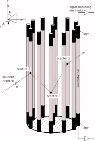
Fig. 1. Schematic of a double neutron scatter in two cylindrical organic scintillator detectors.
Fig. 2. A fully populated radially symmetric neutron imager.
Additionally, if a third n-p interaction is measured, the coordinates of the third scatter would provide the necessary
kinematic information to uniquely define the incident neutron energy and scatter angle n, making the ToF measurement
between the first and second scatters redundant.
Proc. of SPIE Vol. 6945 694509-3
Data from two or more n-p interactions are sufficient to constrain the direction of the incident neutron onto the mantle of a cone about the recoil neutron velocity vector. By projecting the incident neutron cone onto a plane in the far-field, one can define an “event circle” for this particle, shown at the top of Figure 1. The intersections of many such cones from individual neutron detections will bunch (actually in three dimensions) at the location of the neutron source. In general, if the velocity vector of the first recoil proton were known, the cone would collapse to vector pointing to the neutron source. However, at FNIT energies the recoil proton cannot be tracked due to its short range in solid matter. Thus, one can only measure the proton kinetic energy.
4
. SCIENCE MODEL 2
Earlier versions of the instrument we have developed on the bench have been published at other SPIE meetings8, 9. They suffered primarily from an elevated energy threshold, thereby missing the peak of the Watt spectrum at 1 MeV. The version that we present below possesses a much lower threshold allowing it to capture the majority of the Watt spectrum for analysis and imaging. The idea for this design was spawned by the need for a radially symmetric instrument for a spinning spacecraft, but has obvious applications suggested below. Science Model 2 is a prototype or bench model of a larger, or fully populated, instrument that would possess an efficiency that is radially symmetric allowing it to survey an entire volume from the inside out.
As alluded to in Fig. 1, the Science Model 2 is comprised of cylindrical or rod-like detectors assembled as sketched out in Fig. 2. The fundamental detector unit is a hollow aluminum rod filled with liquid scintillator. A single rod is shown in Fig. 3. Each rod is viewed by two photomultiplier tubes (PMT). The PMTs measure the total light output and the ratio of the signals in the two tubes is used to locate the scintillation along the length of the rod.
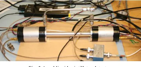
Fig. 3 A rod liquid scintillator detector.
Each rod is 1.5 cm in diameter. This dimension was chosen as a compromise between keeping PMTs and data channels to a minimum for a fixed volume of scintillator and, simultaneously minimizing multiple neutron interactions within a rod, i.e., the probability of two scatters by the same neutron in a rod is less than 10%, even at the lowest energies. The rods are currently 15 cm in length. The bench model consists of three such rods.
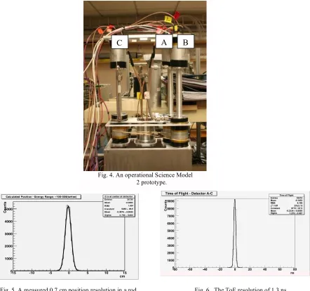
As shown in Figs. 1 and 2, a neutron scatters in one rod and subsequently scatters in another. The four pulse heights are recorded and the ToF is measured. The liquid scintillators used in the bench model all possess pulse shape discrimination properties. The pulse shape is also measured for the sum of the two PMTs of each triggered rod. Science Model 2, the prototype instrument in an operating configuration is shown in Fig. 4. Detectors A and B are the first scattering units and Detector C serves as the secondary scatterer.
Two of the rods (A and C) were filled with NE213A while the third (B) was filled with BC519. BC519 offers greater target area for neutron scattering, provided one can tolerate the reduced pulse height and the poorer PSD and ToF resolution. We are only reporting here on the results from scatters between the NE213A detector units.
I)
-4000 —
3000
2000:
1000
-I cs.uss Pn.n -
—io.."i I
L..IJL
?15 -10 -5 0 5 10 15
cm
Shown in Fig. 6 is the ToF resolution between rods. A 60Co source placed midway between two rods produced
simultaneous signals in both rods. The ToF resolution at 1 MeVee is of order 1 ns, commensurate with the length of the
rod. Such a resolution is more than sufficient to distinguish -ray scatters from neutron scatters in this energy range. For example, a 1 MeV neutron traversing the 15 cm between rods requires ~11 ns. Thus, the ToF measure is also used for an energy measure of the recoil neutron. This works well, and confusion between -rays and neutrons is only apparent at the high end of the Watt spectrum where there are few neutrons. As we will show below, at the higher energies where ToF becomes ineffective, the pulse shape discrimination supplants ToF as the species identifier.
Fig. 5. A measured 0.7 cm position resolution in a rod. Fig. 6. The ToF resolution of 1.3 ns.
From controlled Compton scatters, we measured the intrinsic energy resolution. The energy resolution for a single detector rod is 10% at 374 keVee, averaged over the entire rod length10. This value implies that a single detector rod can
achieve a threshold detection at 20 keVee. For a recoil proton, this threshold corresponds to 200 keVpe. For a legitimate
neutron double scatter event, threshold must be exceeded in two detectors with sufficient margin to provide a range of scattering angles that the instrument is sensitive to. Thus, the instrument threshold is not simply 2200 keV, but more like 1 MeVpe.
Operating in the double-scatter mode, data are recorded on a neutron-by-neutron basis. For each registered neutron, four pulse heights, two PSDs and one ToF value are recorded. The pulse heights must be normalized and calibrated
Fig. 4. An operational Science Model 2 prototype.
A
B
C
Proc. of SPIE Vol. 6945 694509-5
Beam Time-of-Flighty. APSD I Bnn'TOF V. APSD I Entries 487451 Mesnx 11291 Meany 6&8 RMSx 2052 .Mc 4
600 800 1000 1200 1400 1600 1800
Detector A - PSD (ADC ch)
I SS, 1M W*'4 tY su, I
-00 -60 -40 -10 0 10 40 60 00
Do etees
Norm•IUsd
Counta (a
o u a u 0 Cfl IPII!_!juuI_!_l I ID
I
ID<<C
(including removal of pedestals), while the ToF value for simultaneity and the scale constitute the calibration curve for that parameter.
To characterize the bench model we exposed the instrument to -ray sources and an Am-Be neutron source, before
taking it into the field. Thorough calibrations were performed at UC Davis, Crocker Nuclear Lab with
quasi-monoenergetic neutron beams11. Afterward, at PNNL, the instrument was exposed to a 252Cf source and WG Pu. The
results of these exercises are described below.
5
. NEUTRON DETECTOR CHARACTERIZATION
Beams of 1, 2, 5, 10 and 18 MeV neutrons were produced at the Crocker Lab. Coming from the cyclotron was a shaped RF pulse that constituted the STOP for a time-to-amplitude (TAC) as a means to identify the monoenergetic part of the neutron spectrum emerging from the cyclotron target. The START signal came from either Detector A or B. The output of the TAC we called the Beam-Time-of-Flight (BToF). It was encoded in the data stream along with the data generated in the instrument itself. Monoenergetic neutrons should be restricted to a narrow range of BToF. However, at these low energies, the monoenergetic part of the beam was overwhelmed by
intense -ray background as well as neutrons of all
lower energies. To sharpen up the signal to find the proper BToF interval, we first selected data that had neutron ToF (instrument-only data) values. We then
plotted all the data onto a BToF/PSD plot (Fig. 7). The monoenergetic peak emerged once we selected data from that 3-D data space.
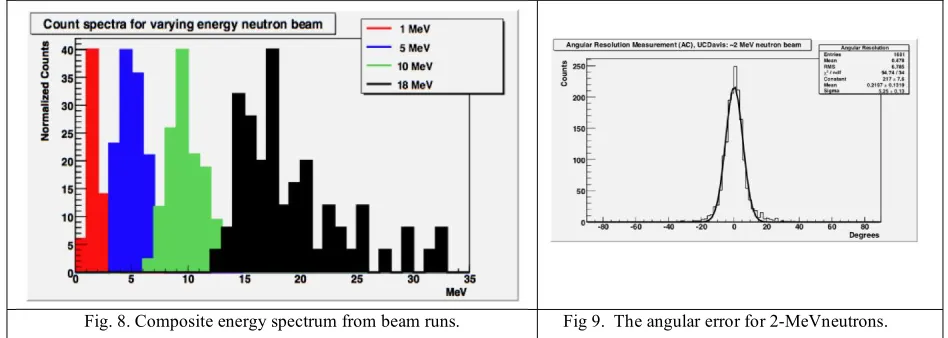
Having selected quasi-monoenergetic neutrons, we constructed an event cone or circle for each detected neutron. We projected those cones onto an image plane at the distance of the beam target. If the cone intersected the plane within 50 cm of the beam target, the event was deemed to be a full-energy measure of the neutron and was included in the energy count spectrum. A composite spectrum is shown in Fig. 8.
Fig. 8. Composite energy spectrum from beam runs. Fig 9. The angular error for 2-MeVneutrons.
In Fig. 9 is a plot of the angular error between the position of the beam target and the closest approach of the event cone.
The distribution is narrow with a of 5.2˚ at 2 MeV and 4.8˚ at 10 MeV. Even though the signal strength is much
greater at 10 MeV, the angular resolution is driven by the geometrical uncertainties in the locations of the scatters and the small size of the instrument.
SQ. S IS@4IClPflt)
EnI,1es 52562
Ilex •01061
MONIY 001667 RUSs 07645 —
RUSy n
I zv.x I
100
P1.239. En (Count SDectrum I I Pu.239 I
Ma
After a successful beam calibration, the detector was taken to PNNL to expose it to 252Cf and WGPu sources to measure
how it responds to full spectrum fission neutrons. For security reasons, the WGPu source was small and the exposure long due to the small size of the instrument prototype. The resulting neutron energy spectrum is shown in Fig. 10 and the image as constructed from the intersection of event cones is shown in Fig. 11.
Fig. 10. A measured Watt spectrum superposed with the
theoretical curve. Fig. 11. The image produced by the intersection of event cones.
6
. DISCUSSION AND CONCLUSIONS
A minimally populated prototype of FNIT successfully imaged calibrated neutron beams and realistic fissile sources. A fully populated version of this instrument is in design. Studies are also underway to evaluate the performance if BC519 is used instead of BC501 or NE213A.
A 5˚ angular resolution would be sufficient to locate a source of neutrons within 1 m at a distance of 10 m. The FNIT
ability to measure the spectrum also implies that if a fissile object is segmented and widely distributed within a container volume, although no image(s) may emerge, the spectrum will reveal and confirm the presence of naturally fissile isotopes.
Because the instrument employs ToF on a ns time scale, it naturally lends itself to active interrogation applications when
used with a neutron generator that chops the beam on a s time scale, making it sensitive to the early emissions of
induced fission neutrons.
REFERENCES
[1] Bramblett, R.L., Ewing, R.I., and Bonner, T.W., "A New Type of Neutron Spectrometer," Nucl. Instr. Meth. 9, 1-12
(1960).
[2] “Solar Sentinels: Report of the Science and Technology Definition Team” in Solar Sentinels Executive Summary
2006 [Online]. Available: http://sentinels.gsfc.nasa.gov/SentinelsExecSumm.pdf (2006)
[3] Moser, M.R., et al., “SONNE: A Telescope for Imaging Solar Neutrons Below 30 MeV in the Inner Heliosphere,”
Proc. The Second Solar Orbiter Workshop (2006).
[4] Watt, B.E., “Energy spectrum of neutrons from thermal fission of U235,” Phys. Rev. 87, 1037-1041 (1952).
[5] Moser, M.R., et al., “Atmospheric Neutron Measurements in the 10-170 MeV range,” Proc. 29th Int. Cosmic Ray
Conf. 00, 101-104 (2005).
[6] Slaughter, D. et al., “Detection of special nuclear material in cargo containers using neutron interrogation,”
Lawrence Livermore National Lab, UCRL-ID-155315 (2003).
[7] Knoll, G. F., [Radiation Detection and Measurement], 3rd ed. New York: Wiley, 553-563 (2000).
[8] Bravar, U. et al., “Imaging solar neutrons below 10 MeV in the inner heliosphere,” Proc. SPIE, 5901, 141-150
(2005).
[9] Bravar, U. et al., “FNIT: the fast neutron imaging telescope for SNM detection,” Proc. SPIE,6213, 62130G (2006).
Proc. of SPIE Vol. 6945 694509-7
[10] Bravar, U. et al., “Design Optimization and Performance Capabilities of the Fast Neutron Imaging Telescope
(FNIT),” IEEE Trans. Nucl. Sci. Symp. Conf. Rec., N14-5 (2007).
[11] Jungerman, J.A., and Brady, F.P., “A Medium Energy Neutron Facility,” Nucl. Instr. Meth., vol. 89, 167-172
(1970).
[12] Macri, J.R. et al., “The Fast Neutron Imaging Telescope (FNIT) – Hardware Development and Prototype Testing,”