Effect of Effective Refractive Index of
Grating in FBG Splitter
DINESH ARORA
Research Scholar (ECE), Singhania University, Jhunjhunu, Rajasthan-333515, INDIA
Dr. JAI PRAKASH
Professor in Department of Applied Physics, Indo Global College of Engineering, Mohali, Punjab-140109, INDIA
HARDEEP SINGH
Associate Professor in Department of ECE, Indo Global College of Engineering, Mohali, Punjab-140109, INDIA
Tel: +91-99880-16668
Dr. AMIT WASON
Professor in Department of ECE, Rayat & Bahra Institute of Engineering & Bio-Technology, Mohali, Punjab-140104, INDIA
Abstract- The Fiber Bragg Gratings have been used extensively in the communication industry. Fiber Bragg grating is written directly into the core of the optical fiber and it is quite an attractive technique for wavelength splitter since it provides high reflectivity at a certain wavelength, with negligible transmission losses for others, providing a wavelength-channel selection with low crosstalk between adjacent channels.In this paper we propose a Fiber Bragg Grating base splitter with alteration of effective refractive index of grating for Ethernet passive optical network. With the increase in the effective refractive index the reflectivity of grating is increased. We analysed the effect of effective refractive index on reflectivity of grating. In our work the Bragg wavelength has been fixed at 1550 nm, length of the grating as 10mm and with effective refractive index as 4.0 it has been found that the reflectivity of the grating or the effectiveness of the grating in extracting the wavelength is 92-93%.
Index Terms-Fiber Bragg Grating; Reflectivity; Grating length; Effective refractive index of Grating.
1. INTRODUCTION
An optical fiber is an optical waveguide based on the principle of total internal reflection. In general, a proper description of the characteristics of an optical fiber is derived by solving the Maxwell’s equations. However, in order to get a general overview of the function of an optical fiber, it is suffice to consider the approximations of geometrical optics. In geometrical optics, Snell’s law dictates that light passing through an interface between two different materials refracts according to the relation:
Where η1 and η2 are the refractive indices of the two materials and θi and θt are the incidence and transmission angles
respectively. If , then θt >θi, that is, if the first material has a higher refractive index than the second
material, the transmission angle will be larger than the incidence angle. If the incidence angle is as large as the transmission angle would be, no light can be transmitted and instead all light will be reflected. This angle is called the critical angle (θc).
sin (2)
A standard telecom optical fiber usually has a core diameter of approximately10 μm and a cladding with an external diameter of approximately 125 μm and can be manufactured to be several kilometres long.
In today’s era internet is growing day by day and the capacity requirement is increasing rapidly. This rapid increase in the requirement of capacity can be met by optical fiber communication. Fiber Bragg Grating (FBG) plays an important role in optical fiber communication. The FBG was initially demonstrated by Ken Hill in 1978.These gratings were fabricated using a visible laser, propagating along the fiber core. FBG are created by ‘inscribing’ or ‘writing’ systematic variation of refractive index into the core of a special type of optical fiber using an intense ultraviolet (UV) source such as a UV laser. Two main processes used are interference and masking. The methods used for creating FBG depend on the type of grating to be manufactured. A special germanium-doped silica fiber is used for the manufacturing of FBGs. In germanium-doped fiber the refractive index of the core changes with exposure to UV light and refractive index varies with variation in the amount of the intensity and duration of the exposure.
Interference: This method is specifically used for uniform gratings. UV laser is split into two beams which interfere with each other creating a periodic intensity distribution along the interference pattern. The refractive index of the photosensitive fiber changes according to the intensity of light that is exposed on it. Photo-mask: The Photo-mask is placed between the UV light source and the photosensitive fiber. The
shadow of the photo-mask then determines the grating structure based on the transmitted intensity of light striking the fiber. Photo-masks are specifically used in the manufacture of chirped FBGs, which cannot be manufactured using an interference pattern.
Point-by-point: A single UV laser beam may also be used to 'write' the grating into the fiber point-by-point. In this technique the laser has a narrow beam that is equal to the grating period.
1.1. Fibre Bragg Grating (FBG)
FBGs are attractive as optical filters owing to their low insertion loss, compactness and cost efficiency [1].These are formed by periodic variations of the refractive index in the core of an optical fiber. These periodic variations allow a FBG to pass the majority of light propagating through a fiber while reflecting back a narrow band of the incident light with a particular peak wavelength called the Bragg wavelength [2].
Fig.1. Principle of operation of a Fiber Bragg Grating.
not satisfied, the reflected light from each of the subsequent planes becomes progressively out of phase and will eventually cancel out. Where the Bragg condition is satisfied, the contributions of reflected light from each grating plane add constructively in the backward direction to form a back-reflected peak with a center wavelength defined by the grating parameters. & p are the effective indices of refraction of the fiber and the pitch of the grating in the fiber respectively. Depending on the intensity and pitch of the grating, numerous types of functions have been proposed. The reflected wavelength is given by the Eq. (3):
2 p (3)
The Bragg relationship in its differential form is given by Eq.(4):
Δ Δ Δ (4)
These equations state that any measurable quantity applied to the grating that causes a refractive index change or period change, induces a deviation in the resonant wavelength.
A uniform grating can be represented by a sinusoidal modulation of the refractive index of the fiber core given by Eq.(5):
1 (5)
1.2. Sensors
FBG sensors are based on the fact that the Bragg wavelength changes with change in the pitch of the grating and the change in the refractive index. Thus, any physical parameter (like temperature, strain, stress) which causes changes in the above mentioned parameters can be sensed using a FBG, by measuring the shift in the Bragg wavelength or the change in reflection coefficient of a particular wavelength [3].
Optical fibre sensors and their systems have the following advantages [4, 5, and 6]:
The low transmission loss of optical fibre enables remote sensing over tens of kilometres.
Real time monitoring is achieved by connecting the sensor heads directly to the measuring equipment using optical fibre.
Easy to install due to small size. Can be multiplexed.
High sensitivity.
Integrated telemetry: fibre itself is a data link. Possibility of remote, multiplexed operation.
2. LITERATURE SURVEY
the refractive index. Their results proved that the increase of the grating length causes the decrease in bandwidth and the increase of the reflectance at the Bragg wavelength. This could be used for narrow-band wavelength selective filtering. Mohammad Syuhaimi; et al [10], worked on the effects of refractive index of cladding to Bragg wavelength and reflection in waveguide Bragg grating filter. The increase of cladding index value in certain duration does not affect the reflected wavelength. The range was bigger when the values were far from the core index and the size becomes smaller when the cladding index values achieve the core index value. Bashir Ahmad Tahir; et al. [11], described a FBG sensing system for strain measurements. They investigated the two parameters reflectivity and Bragg wavelength shift. They observed a negligible change in reflectivity by changing in index modulation from 0.0001 and 0.0008.The average value of reflectivity was found to be 95% .The reflectivity almost remains constant, even though by varying the index modulation. Tran Thi Tam; et al [12], investigated the temperature responses of the FBGs. It was found that these responses ranged from 10.6 pm/°C to 12.0 pm/°C. The temperature sensitivity of the FBGs was 0.2°C. Although the temperature response is nonlinear over the temperature range 20°C to 180°C, in practical systems the temperature response of the sensor may be assumed to be linear within the temperature range 20°C to 80°C.
3. ANALYTICAL MODEL
In this paper, a wavelength splitter has been proposed for single mode fiber using FBG. The Analytical model has been proposed for the reflectivity of grating which is given by Eq.(6).
Assumptions:
Length of Grating, l =10mm
Index difference between core and cladding, Δ = 0.0036 Bragg Wavelength, 1550.08 nm
Radius of core, a= 4.5µm
Index amplitude of grating, 1X10
Reflectivity:
(6)
(7)
(8)
p (9)
(10)
η=Δn * Pc (11)
Where
δis detuning factor is propagation constant is pitch of the grating c is coupling coefficient
Here ‘Pc’ is fractional power of core and is given by 1 , where v is the normalized frequency.
4. SIMULATION, RESULTS& DISCUSSION
The simulation is carried out on simulation Software MATLAB 7.2 of Math-works. The simulation model thus constructed has improved the reflectivity of the fiber grating with variation of some of the design parameters. In this paper effective refractive index of grating has been varied to achieve the maximum reflectivity for the wavelengths for Ethernet Passive Optical Networks (EPON).
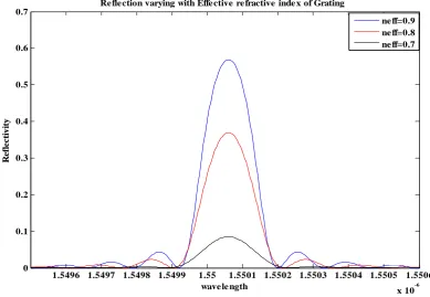
In Fig. 4. Effectiveness of the grating was calculated as 8.49% for 0.7 effective refractive index. It was increased to 36.78% and 56.84% when the effective refractive index was increased to 0.8and 0.9.
In Fig. 5 the reflectivity of the grating was calculated to be 68.49% for the effective refractive index of 1.0, which was increased to 79.82%, 84.79 %, when the effective refractive index was increased to 1.2 and 1.4 respectively.
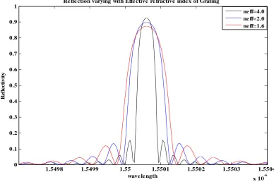
In Fig. 6 the reflectivity of the grating or the effectiveness of the grating was calculated as 87.39% for 1.6 effective refractive index. It was increased to 89.91% when the effective refractive was increased to 2.0. Further it was increased to 92.48% with 4.0 effective refractive index. Now the changes in value of reflectivity are negligible with the variation of effective refractive index so we stopped simulation here.
Fig. 4. Reflection varying with effective refractive index of grating neff =0.7, 0.8 and 0.9
1.5496 1.5497 1.5498 1.5499 1.55 1.5501 1.5502 1.5503 1.5504 1.5505 1.5506
x 10-6 0
0.1 0.2 0.3 0.4 0.5 0.6 0.7
wave le ngth
R
e
fle
c
ti
v
ity
Re fle ction varying with Effe ctive re fractive inde x of Grating
Fig 5: Reflection varying with effective refractive index of grating neff =1.0, 1.2 and 1.4
Fig.6. Reflection varying with effective refractive index of grating neff =1.6, 2.0 and 4.0
1.5496 1.5497 1.5498 1.5499 1.55 1.5501 1.5502 1.5503 1.5504 1.5505 1.5506
x 10-6 0
0.1 0.2 0.3 0.4 0.5 0.6 0.7 0.8 0.9
wave le ngth
R
e
fl
e
c
ti
v
ity
Re fle ction varying with Effe ctive re fractive inde x of Grating
ne ff=1.4 ne ff=1.2 ne ff=1.0
1.5498 1.5499 1.55 1.5501 1.5502 1.5503 1.5504
x 10-6 0
0.1 0.2 0.3 0.4 0.5 0.6 0.7 0.8 0.9 1
wave le ngth
R
e
fl
e
c
ti
v
ity
Re fle ction varying with Effe ctive re fractive inde x of Grating
5.CONCLUSION
We have analysed the effect of effective refractive index of grating on response of reflectivity of Fibre Bragg grating having centre wavelength 1550nm. For effective refractive index of 0.7 to 2.0, reflectivity is not sufficient to extract the wavelength effectively. From the simulation results it can be concluded that reflectivity was sufficient to extract the wavelength effectively with value ‘4’ of effective refractive index of grating when length of grating was 10mm. If we further increased its value the change in reflectivity was negligible. So with the increase in the effective refractive index the reflectivity of grating increases to some extent thereafter changes in values of reflectivity are very small.
REFERENCES
[1]. Ming Li, Takeo Fujii, and Hongpu Li, “Multiplication of a Multichannel Notch Filter Based on a Phase-Shifted Phase-Only Sampled Fiber Bragg Grating”,IEEE Photonics Technology Letters, VOL. 21, NO. 13, July 1, 2009.
[2]. T. Shane Sowers and Kevin J. Melcher, NASA Glenn Research Center, 2005 Research and Technology.
[3]. Reema Sharma, Rajesh Rohilla, Mohit Sharma, Dr.T.C.Manjunath, “Design and simulation of optical Fiberbragg grating pressure sensor for minimum attenuation criteria”, Journal of Theoretical and Applied Information Technology, © 2005 - 2009 JATIT.
[4]. Keisuke Fukuchi,Seijikojima,YasuyukiHishida, “Optical water level sensors using fiberbragg grating technology”, Hitachi cable review no.21(August 2002).
[5]. D-C. Seo, D-J. Yoon, I-B. Kwon, S-S. Lee, “Sensitivity enhancement of fiber optic FBG sensor for acoustic emission”, Korea Research Institute of Standards and Science, Republic of Korea.
[6]. Alexis Méndez, Tom Graver “Overview of Fiber optic sensors for NDT applications”, Alexis Méndezn 4th NDT Panamerican Conference Buenos Aires-October 2007.
[7]. Bashir Ahmed Tahir, Jalil Ali, Rosly Abdul Rahman “Dependence of dynamic range, linearity and sensitivity of fiber Bragg grating system on bonded sensor length”, Optoelectronics and advanced Material – Rapid Communication Vol. 1, No. 1, January 2007 p. 19 – 24. [8]. Ing. RadekHelan,Dr.Frantisek Urban, “Uniform Fiber Bragg Grating properties”, Dept. Of Microelectronics, FEEC, BUT.
[9]. E. Gemzický, J. Müllerová, “Analysis of simulated reflection characteristics of uniform and Apodizedfiber Bragg Grating”, supported by the Slovak Research and Development Agency under the project APVV COST-0041-06.
[10].Mohammad SyuhaimiAb-Rahman and MuhdFauziAminuddinShaziShaarani, “Effects of Refractive Index of Cladding on Bragg Wavelength and Reflection – the Application Proposed”, Australian Journal of Basic and Applied Sciences , 3(3): 2876-2882, 2009. [11].Bashir Ahmad Tahir, Jalil Ali and Rosly Abdul Rahman,“Strain Measurements Using fibre Bragg Grating Sensor”, American Journal of
Applied Science (Special Issue): 40-48, 2005.