SNS: Architecture for Sensor Network-based Services
via Internet Service Provider
Yawar Abbas1, Saima Zafar2, Ali Hammad. Akbar1
1. Department of Computer Science, University of Engineering and Technology, Lahore, Pakistan
2. Department of Electrical Engineering, National University of Computer and Emerging Sciences, Lahore, Pakistan
Corresponding Author: Email: [email protected]
Abstract
Wireless Sensor Networks (WSNs) are envisioned to be widely deployed for monitoring the various phenomena such as environmental factors, seismic activity, weather conditions etc. In order to provide ease of access of sensor network based services to the end users, commercialization of these services has been proposed through sensor web portals which imitate the sensor network access similar to web server access via web page. However, this proposal lacks in sensor portal discovery mechanism, its subscription, security and management. It is due to this deficiency that the sensor network based services are not accessible to the general public despite extensive deployment of these networks. This paper presents a novel architecture; Sensor Network based Services (SNS) which makes use of the widely available and popular Internet Service Providers (ISPs) for hosting, publicizing and securing the sensor web portals. In SNS, we propose a coupling between the web page and the ISP which provides the advantages of a one-window-operation, security and privacy, query content and locality and sensor data cache management. We analyze the various business models for advertising the costs, query and data traffic and mathematically model them in order to evaluate them for SNS. Our analysis validates the effectiveness of SNS in terms of considerable saving in query processing time for a large number of data types and end users.
Key Words:
Sensor-based services, Sensor web portal, Internet Service Provider, Cache management, Business model1. Introduction
The swift development and deployment of WSNs during the last few years has led to an increased interest in optimization of access to the sensory information that can be obtained from these networks. These efforts have resulted in realizing web portals that reside on web server [1] – [4]. A web portal holds hyperlinks that refer to different types of sensor data. When clicked, sensor data relevant to a hyperlink is obtained from appropriate sensor and provided to the end user. Nevertheless from a commercial point of view, we observe that in this type of access mechanism a number of important intermediary steps are bypassed or overlooked. This oversimplification of access mechanism results in loosing commercial utility thereof. Although WSN data may already be available at commercial level through web portal, the access to the portal is impeded in many respects. First, these websites are subjective in capabilities and lack user-friendly names and domains which make their discovery, retention and reusability difficult. The modes of subscription with these websites vary in style and scope. Finally, users of sensor data may have apprehensions about disclosure of their personal
information, profiles, usage pattern or even sensed data, as each web portal may have inconsistent security policies.
In this paper, we present Sensor Network-based Services (SNS); an architecture that defines the role of the ISP in provision of WSN data access to end users while addressing the challenges listed above. The SNS unites the commercial strength, accessibility and maturity of ISP with the value of WSN data in order to provide sensor services to every doorstep without compromising the quality of service. Keeping in view the typical structure of a conventional ISP meant to provide web pages to end users and the contemporary WSN setup, it is but natural that in order to realize WSN service provision through ISP, a complete re-designing of architecture is required for this merger.
A number of design challenges have to be addressed in order to realize the proposed wireless sensor service provision through the platform of an ISP. SNS addresses these challenges by proposing a suitable architecture that facilitates this merger through a one-window-operation for access of both Internet services as well as wireless sensor services. Our contributions include:
A novel architecture for merger of ISP with WSNs for commercializing wireless sensor services addressing the issues and challenges related to this merger.
Provision of optimized location aware and content aware response to user queries.
Introducing caching techniques in web portal websites to provide fast and optimized access to sensor data.
Tackling the security and privacy issues that emerge from such merger.
Suitable business model proposal to fulfill the needs of commercializing of wireless sensor services and to represent the revenue flow for benefit of the organizations that are part of SNS architecture.
Mathematical analysis of proposed business model.
The remainder of the paper is organized as follows. In section 2, we discuss the related work. In section 3, we present comprehensive design of SNS architecture. Section 4 presents suitable business model and mathematical analysis of proposed business model. Section 5 presents performance evaluation of using different pricing schemes for revenue flow. Finally section 6 summarizes the results and concludes the paper.
2. Related Work
Recent research efforts are directed towards WSN performance optimization with an emphasis on commercializing sensory services. In this regard, the role of ISPs has been limited to a point of access to the sensor portals and there is lack of real time sensory data service provision to end users. The ISPs have not taken the initiative yet to make efforts towards offering wireless sensor services to end users the way they provide Internet and related data services. A comprehensive design of ISP architecture can be understood through [5] that includes hardware details and software applications running over the network. However, the paper does not offer insight into utilization of ISP for providing WSN services or architectural components for such services. The need for such architecture is further highlighted in [6]. Some incomplete and deficient work exists which addresses this issue [7]-[17], nevertheless a thorough architecture is missing.
In [7] it is shown that the peering points between different ISPs are among the bottlenecks of the Internet. Multi-homing (MH) and content delivery networks (CDNs) are two solutions to
detour peering points and to improve quality. The authors present a static market model with locked-in end users and paid content. In [8] priclocked-ing models designed for charging clients for sensor data are listed. This work provides useful guideline for initiating a comparison of different pricing models and for evaluating these models for different types of users. The idea of joining web infrastructure with sensor network is discussed in [9]. The authors emphasize the concept of joining both infrastructures but do not provide organizational details, hardware and software requirements for such a collective infrastructure.
Lamparter et al. in [10] present solutions to security attacks in sensor networks. They propose a solution which does not require mutual authentication and provide business model for charging and a security protocol to implement the charging scheme. Security is a major concern in merger of two separate architectures for sensor service provision and this issue is discussed in detail in [13]. This work identifies the security vulnerabilities in web server as a result of malformed message generation.
Muhammad Taqi et al, [14] underline problems regarding real-time dissemination of sensor data towards consumers. They present cache management techniques for storing and retrieving sensor data using soft timer-based cache management but ignore the content of data. Merging of sensor networks with other infrastructures is discussed in [15] which gives an overview of entities which can be involved while merging the two diverse architectures. The authors present a business model for the merged operation but the model is in reference to the mobile network operator and not the ISP. A peer selection algorithm in [16] defines the relationship between different entities at various levels that provide services and generate revenue in ISP. This work focuses on how different peers are selected for peer-to peer applications and on the basis of peer selection algorithms, the business flow is derived.
Paul Timmers in [17] describes a very comprehensive definition of a business model. Different business models are presented and a classification of these business models is given with details of models applicable in the field of electronic commerce. In [18] the authors investigate two different QoS measures: short-term per-slot packet dropping constraint and long-term packet dropping constraint and analyze ISP's time-invariant pricing and develop an upper bound for the optimal revenue by considering the specified packet dropping threshold. In [19] the authors study multi-hop relay networks where
pricing is used as motivation for forwarding traffic. In these networks, nodes price their services to raise its profit from forwarding traffic, and assign their received traffic to service providers to reduce the amount paid.
3. SNS Design
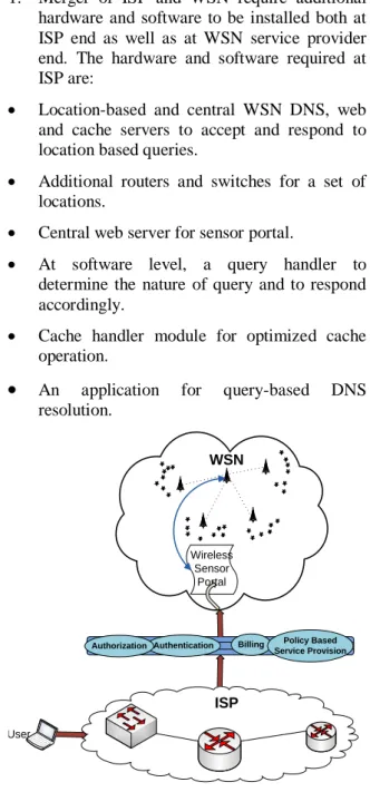
Fig. 1 shows the SNS architecture. The design constraints for the merger of ISP and WSN are listed below.
1. Merger of ISP and WSN require additional hardware and software to be installed both at ISP end as well as at WSN service provider end. The hardware and software required at ISP are:
Location-based and central WSN DNS, web and cache servers to accept and respond to location based queries.
Additional routers and switches for a set of locations.
Central web server for sensor portal.
At software level, a query handler to determine the nature of query and to respond accordingly.
Cache handler module for optimized cache operation.
An application for query-based DNS resolution.ISP Wireless Sensor
Portal WSN
User
Authentication Billing
Authorization Service ProvisionPolicy Based
Fig. 1: Block diagram of the System
The requirements at WSN service provider end are:
Software to keep track of WSN vendors at different locations and their services.
Software for tracking hardware and environment conditions of sensors. Request handler receiving and forwarding instances from ISPs to WSN vendors and vice versa.
Managing portal website on the basis of services from different vendors.
2. Caching techniques on the basis of content and query repetition for requested data needs to be devised.
3. Security threats need to be indicated and addressed before portal website is compromised.
4. Privacy issues for user data need to be identified and addressed.
5. Business model for revenue flow needs to be devised.
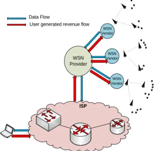
SNS architecture functions with the co-operation of a number of entities. There are three major components of SNS architecture namely ISP, WSN Provider and WSN Vendors as shown in Fig. 2. Customers interact with the ISP and demand sensor services from a list of predefined services available through that ISP.
ISP
WSN Provider
WSN Vendor
WSN Vendor WSN Vendor
Response Request
Fig. 2: SNS Architecture: Macro-view
WSN Provider keeps track of WSN Vendors operational in the locality of subscribed customers. WSN provider is responsible for designing and updating web portal to be used by customers for accessing their dedicated pages and for using their subscribed services. WSN Vendors are responsible for providing sensor services,
installing sensors at the sites and for maintenance of installed equipment.
3.1 ISP End Details
New hardware needs to be installed at ISP. These additional devices are:
Central Web Server (CWS): Through which all sensory information is provided to customer.
Central DNS (C-DNS): Installed for sensor query resolution on the basis of Uniform Resource Identifiers (URI) and Uniform Resource Locators (URLs). C-DNS in turn has information of all the local DNS servers. Local DNS (L-DNS): Installed for resolution
of local queries. It performs same operation as C-DNS, but on a local scope.
Local Web Server (LWS): Contains a mirrored copy of web portal from central web server. It may use any RAIDlevels.
The role of these devices is discussed further while taking a look at the query flow of customer.
3.1.1 Query Flow of customer
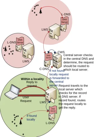
The customer initiates the request to connect to ISP for WSN services. First, a C_Request query is generated from the Customer Premises Equipment (CPE) and is sent to the customer’s local exchange where ISP equipment is placed. This query is routed to LWS, which has a query handler module that checks the type of query and takes decision. Two types of queries arrive at the LWS, connection requests and data requests. While the C_Request query is sent from CPE to web server, the request handler module identifies it as connection request and forwards it to the core data center for authentication. Then data requests are generated by the CPE. Fig. 3 shows two scenarios for data requests from client to web server, explained below:
Scenario1: D_Request is sent as data query from
customer end. LWS identifies it as data request and forwards it to L-DNS. L-DNS resolves the query and directs the request to the appropriate sensor. When information is retrieved from sensor, it is sent to LWS which responds to the user query and sends user demanded data.
Scenario 2: D_Request is sent as user required
data query from customer end. Web server identifies it as data request and forwards it to L-DNS. L-DNS checks and is unable to resolve the query. For further processing it sends the query to C-DNS which checks its database and routes query to the appropriate sensor. The information is
retrieved from the sensor and in the reverse order, sent to the user through its LWS.
User Request
Request travels to the local server which checks for the record in DNS server. If record found, routes the request locally to get the reply.
If found locally
If not found locally request is forwarded to the central server.
Central server checks in the central DNS and determine, the request should be routed to which local server.
Within a locality
Reply to request
DNS Server
DNS Server DNS Server
DNS Server
LWS
L-DNS CWS
C-DNS
L-DNS
LWS
LWS L-DNS
Fig. 3: Query-driven micro-view in SNS
3.1.2 DNS & the concept of locality
Location-based query resolution is a major design objective of SNS and the discussion in last subsection reflects that this objective is achieved with the combined action of L-DNS, LWS, C-DNS and CWS. LWS can respond to some queries from users in its location while unresolved queries are forwarded to CWS. This localized query resolution concept offers two benefits. The benefit to users is swift response time against their queries especially if they are localized. The advantage to organization is reduction in network traffic as those queries that are resolved locally do not propagate through the whole network every time the user generates query. Also it results in reduction of load on central web server.
3.1.3 Cache management
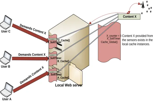
In SNS there is separate caching for each user. We introduce a cache handler module that has its instances working for each user. Specific data content when demanded by the user is retrieved from the sensor network and is recorded by cache handler module on reaching the LWS.
The module then creates an instance for that user that is attached permanently with the user's web account. The cache handler module maintains a count for each of the demanded content. When another user demands the same content, the cache handler module increments its counter by one for that content, and creates another instance for the second user and so on. If the content is demanded repeatedly from many users, the cache handler module adds it to the global address space and removes copies of content from individual user cache instances. This is done for avoiding replication of the same content on web server. The algorithmic details can be understood through the following scenario: User A demands content X. Query arrives at web server and content is provided to the user. Cache handler module en-caches the content of data and creates an instance A_Cache( ) for user A containing the copy of content X, and attaches it with web address space allocated for that user. The cache handler module also maintains a counter for the content, X_Counter and increments it whenever the content is demanded again by some user.
Now another User B demands the same content. The cache handler module creates an instance B_Cache() for that user containing the copy of demanded content and attaches it with web address space allocated for that user incrementing X_Counter. When the counter exceeds a threshold value, it means the content is demanded repeatedly by different users and local copies are increasing in number therefore the module deletes all local copies and adds the copy of that content to the global caching instance Cache_Global().
It is important to note that whenever same user demands the same content, web server searches for it in local cache instance. If found the content is provided to the user. If not found in local instance, global cache instance is consulted. When the content is not available in local web server, the query is forwarded to central server which checks its cache. The local and global cache instances also keep track of how often the content is seen over a specific amount of time to decide about soft timer for data retention. When soft timer expires, data is deleted and counters are reset. Fig. 4 and 5 show the above mentioned scenario along with procedures.
The cache handler has another important responsibility of determining the content of data and on its basis, deciding soft-timer, at the expiration of which the content is flushed from cache. In order to determine the nature of demanded content, the cache handler utilizes
Network Based Application Recognition (NBAR). NBAR™ allows network routers to recognize the type of en-route data and take various actions based on that information. NBAR™ is a Cisco® proprietary feature that enables the routers to access and process information from Layer 4 through Layer 7. The feature was designed for application recognition. Whenever demanded content passes through gateway devices, data is un-wrapped from its application layer header and NBAR™ determines the nature of demanded content. This information is utilized by cache handler module to decide soft-timer for the contents. The cache maintains separate thresholds of soft-timer for different types of data. Whenever soft timer expires, the content is flushed.
3.2 Security and Privacy
Security and privacy of user data is an important concern in WSN services. The service architecture must be able to deal with threat and intrusion management for WSN commercialization through ISPs in order to gain trust in both privacy and performance. Since ISPs have matured through decades in Internet service provision, these are prepared as well as equipped for threats and security vulnerabilities. While providing large scale Internet services and managing huge amount of traffic and users vulnerable to attacks, ISPs keep track of traffic patterns based on time of usage. Whenever a device is attacked, unusual traffic patterns are generated which in turn are identified and treated there and then before the attack may harm services. This makes ISPs the most suitable choice for the provision of WSN services. SNS architecture has two important entities in addition to ISP, these are the WSN provider and WSN vendor which necessitates modification in policy as far as security is concerned. We discuss this policy as follows. The ISPs are responsible for generating traffic patterns for various sensory services. The Multi Router Traffic Grapher (MRTGs) of aggregated traffic of a collection of sensor nodes is introduced. Along with aggregated traffic of a collection of sensors, traffic patterns of sensory data from different vendors are also recorded. These MRTGs are monitored for detecting abnormal patterns and a copy of these is handed over to the WSN provider.
User A User C
User B
Local Web server
Cache_Global()
Demands Con tent X
Demands Content X
Dem ands
Con tent X
Content X
Content X Content X Content X
A_Cache() B_Cache() C_Cache()
X_counter = 3Content X provided from the sensors exists in the local cache instances.
X_SoftTimer
X_SoftTimer
X_SoftTimer X_SoftTimer
Fig. 4: Cache Operation when same content is demanded by few users and the cache counter is less than
threshold
User A User C
User B
Local Web server
Demands Content X
Content X
A_Cache() B_Cache() C_Cache()
X_counter = 25
Demands Content X
Dema nds Cont
ent X User Z
Deman
ds Content X .
. . .
Z_Cache()
Copies of content X deleted from individual cache instances
Copy of content X is kept in the global cache
of local web server X_SoftTimer
Cache_Global ()
Fig. 5: Cache Operation when same content is demanded by large number of users and the counter
exceeds the threshold
Threshold values are defined for each type of sensor data on timely basis. Once the aggregated traffic exceeds the threshold value for a specific site, system generates alarm to report abnormality. Once the alarm is generated, the suspected site is checked and reported to the WSN provider that resolves the issue by blocking the
node being attacked or generating malformed messages. In addition at ISP end traffic passing through local and central web servers is also recoded and security techniques are implemented at gateways as well as network core such that the attacks are treated before they reach web servers to create degradation or denial of services.
Another important concern is guarantee of privacy of user data. The ISP signs a legal agreement with the user as well as with WSN provider and WSN vendor that ensures the user about prevention of data leakage during delivery. In case information leakage is reported, the ISP assumes reimbursement to user and takes responsibility of legal action against culprit. Thus the responsibility of ensuring security and privacy of user data lies with the ISP which is the most important, resourceful and mature service provision entity.
4. Business Model
The business model i.e. the revenue flow for SNS is challenging due to lack of handshake policy between ISP and WSN providers or vendors. Payments by customers are shared by the stakeholders. In terms of business model, the ISP offers two types of services to the customers. 1. Prepaid services as pay per subscription
services and
2. Postpaid services as pay per byte services Pay per subscription services are offered to the customer as a list of services along with monthly subscription charges for selection of the required services. Once selected, payment information of customer is added to billing application of ISP that charges accordingly. Pay per byte services provides access to the customer to use any service. These services include line rent which is payable by the end of every month along with charges for bytes used during whole month. The users are charged based on the type of demanded content. The NBAR feature is used again to record the nature of demanded content in order to charge the user accordingly. If the user-demanded contents are simple, i.e. no video, audio or image data is requested, the customer is charged less. If the customer demands complex content containing, audio, video data or images, the router recognizes it at application layer through NBAR and the user is charged according.
Now we discuss vendor generated revenue. The vendors are charged by WSN providers for advertisement of their services and for providing business each time a new service subscription is made. After installation of equipment, vendors charge WSN provider as pay per byte. ISP pays a part of revenue generated from each user to WSN service provider that in turn shares this revenue with vendors. WSN service provider shares the revenue generated through vendors with the ISP. Vendors pay to WSN service providers (one time only) for providing them business as an
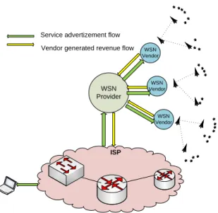
investment for the future. When their services become popular and common, they could be asked to launch more services and get revenue from each of the subscribed user as a percentage. WSN provider shares percentage of their revenue by vendors with ISP because ISP is responsible for the advertisement and demand for their services. WSN service provider gets revenue from both WSN vendor and ISP as ISP pays WSN service provider for each user subscribed for services. At ISP end, the revenue is again generated in two ways. WSN provider pays ISP for advertisement and provision of their services to the subscribers. Fig. 6 and 7 show data flow, service advertisement flow and the revenue flows.
4.1 Packet-Trade Model
Most
appropriate
model
for
SNS
architecture is the “Packet-Trade Model”.
This model suggests that each seller sells its
packet to the next buyer for a certain
amount (called
nuggets
) until it reaches the
destination.
Each
entity
involved
in
transmission sells its packet to the next
entity for a value of Z nuggets. The next
entity forwards the packet further adding Z
nuggets.
ISP
WSN Provider
WSN Vendor
WSN Vendor WSN Vendor
Data Flow
User generated revenue flow
Fig. 6: Data Flow and User Generated Revenue
ISP WSN Provider
WSN Vendor
WSN Vendor WSN Vendor
Service advertizement flow Vendor generated revenue flow
Fig. 7: Service Advertisement and Vendor
Generated Revenue Flow
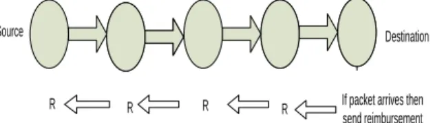
Finally the packet reaches the destination which is the ultimate buyer of packet. The destination has to pay for the whole cost of packet delivery. Example of packet trade model is Fig. 8 (Courtesy [4]).
In our business model while we talk about user generated revenue, the ultimate buyer is the user and the ultimate seller is WSN vendor. WSN vendor takes part of revenue and offers services to its next hop entity i.e.
Seller Buyer Seller Buyer Seller Buyer Seller Buyer
Z=1 Z=1+1
Z=2
Z=2+1 Z=3+1 Z=4
Fig 8: Example of Packet-Trade Model
WSN service provider. WSN service provider keeps its part of the revenue and sells its services to ISP. The ISP determines its revenue through cost analysis takes it and finally provides services to user.
The user pays for expenses in the way through. Our model is evaluated in terms of packet trace model shown in Fig. 9. Considering WSN vendor generated revenue, the advertisement of WSN services is sold. Each entity in SNS architecture sells advertisement to the next entity. ISP is the ultimate seller that is responsible for advertising WSN services and gets revenue for that. WSN service provider buys advertisement of WSN services from ISP and sells these to WSN vendor. WSN vendor is the ultimate buyer and
pays amount for advertisement of services. The model is shown in Fig. 10.
4.2 Mathematical Modeling of the
Proposed Business Model
We now mathematically analyze our business model. List of notations in given in Table 1. We develop expressions for revenues of the involved entities. In our suggested business model, there are two sources of revenue for WSN vendor i) deployment and maintenance of WSN ii) payments from WSN service provider. The revenue of WSN vendor is given as:
d R vw R v
R (1)
WSN
Vendor ProviderWSN ISP User
Z=20% for
each user Z=30 % for each user
Z=50 % for
each user Z=100
User pays 100 which is the sum of all intermediary nodes
Fig. 9: User Generated Revenue
ISP WSN
Provider
WSN Vendor
Z=60% for each advertisement
Z=40 % for each
advertisement Z=100
WSN vendor pays for its service advertisement which is the sum of other entities.
Fig. 10: Vendor Generated Revenue
Table 1: List of notations
Par ame ter
Description
Par ame ter
Description
Rw
Revenue of WSN service provider
Rd
Revenue from deployment Ri
Revenue of
ISP Cd
Cost of deployment Rv
Revenue of
WSN vendor Cm
Cost of maintenance Riw
ISP’s revenue generated by WSN service provider
Tw
Equipment warranty time expiration factor
Rwi
WSN service provider’s revenue generated by ISP
α
Service charges for equipment deployment Rwv
WSN service
revenue generated by vendor Rvw WSN vendor’s revenue generated by WSN service provider Up Payment of user
* Revenue is expressed in local currency In equation (1),
vw
R is the fraction of
payment from ISP to WSN service provider for WSN services such that WSN service provider keeps its share of profit and pays to vendor. Thus:
s P
wi R
vw
R (2)
where 1
s P
. d
R is represented by the following
equation: w T m C d C d R . (3) where m C w orT w
T 1
. In Equation (3), w
T is
the expiration factor of warranty time for deployed hardware which is 1 in case the hardware is to be repaired under warranty claim and equals
m
C in
case the hardware to be repaired is not under warranty claim. Putting the values back in Equation (1) we have:
s P wi R w T m C d C v R
. . (4)Having calculated the revenue generated for WSN vendor we now focus on revenue for WSN service provider. WSN service provider gets its revenue in two ways i) payment made by ISP for service provision and ii) payment made by WSN vendors for service advertisement. It is important to note that WSN service provider has multiple WSN vendors for service provision. Let n be the number representing WSN vendor and N the total number of WSN vendors associated with WSN service provider. Revenue for WSN service provider is mathematically represented as:
nN n
wv R wi R w R
1 ( ) (5)
Putting the value of
wi
R from Equation (2):
N
n Rwv n
s P vw R w R
1 ( ) )
.
( (6)
The revenue generated by payment of WSN vendor to WSN service provider for the advertisement of services is (
s
P ) fraction of total
revenue of a WSN vendor. We re-write the equation as:
N
n Rv n
s P s P vw R w R
1 . ( ) 1
) .
( (7)
Putting the value of
v
R in above equation, we get:
n N n s P wi R w T m C d C s P s P vw R w R
1 . . 1 ) . ( (8)
We now develop expression for
i R . The
revenue of ISP depends upon customer payment (
p
U ) and WSN service provider payment for
advertisement of services by each vendor (
wi
R ).
The ISP makes payment to WSN service provider, the amount (
wi
R ) is deducted from overall
revenue of ISP. The equation can be written as:
N
n Riw n
wi R p U i R
1 ( ) (9)
Putting the value of
wi
R from (9):
nN n
iw R s P vw R p U i R
1 ( ) )
.
( (10)
In Equation (10)
iw
R i.e. the revenue generated through payment of WSN service provider for advertising the services of WSN vendors is fraction (
s
P ) of payment made by WSN vendor to
WSN service provider. Therefore:
Nn Rv n
s P s P n iw R
1 . ( ) 1
. 1 )
( (11)
Nn Rv n
s P s P s P vw R p U i
R ( . ) 1 1 . 1 . ( ) (12)
N
n Rv n
s P s P vw R p U i R
1 ( )
. 2 1 ) . ( (13)
Putting value of (n)
v
R in above equation, we get:
N
n
n s P
wi R
w T m C d C
s P s P vw R p U i R
1 .
. 2 1 ) . (
(14)
5. Performance Evaluation
We evaluate SNS for business and revenue flow. There are a number of pricing schemes, each suitable for certain type of WSN service provision. We compare appropriate pricing schemes and evaluate these for SNS under different scenarios.
5.1 End-to-End
Successful
Transmission
Reimbursement
Scheme (EESR)
In EESR every sending entity involved in transmission of packets receives reimbursement if packet is successfully reaches destination. The pricing information needs to be aggregated at the destination. Pricing information includes path and number of bytes transferred, as shown in Fig. 11.
5.2 End-to-End Retransmit Attempts
Reimbursement Scheme (ERSR)
This scheme is similar to EESR and gives advantage to the transmitter. The transmitter receives reimbursement for making retransmit attempt in case of packet delivery failure in first attempt. The transmitter gets reimbursement for unsuccessful delivery along with reimbursement for retransmitting packets.
5.3 Hop-by-Hop Successful Delivery
Reimbursement (HHSR)
Each of the intermediate entities involved in packet delivery is reimbursed, regardless of packet reaching the destination. Pricing information needs to be maintained on each node so that the sender may not claim delivery of more packets, Fig. 12.
Fig. 11: Example of EESR
Fig. 12: Example of HHSR
5.4 Hop-by-Hop
Retransmit
Attempts
Scheme
for
Reimbursement (HRSR)
This scheme is the same as HHSR, with an added incentive of reimbursement to each intermediate entity for a retransmission attempt it makes.
5.5 Comparison of Pricing Schemes
With Respect to Services
In order to compare different pricing schemes in terms of services, we need to divide services in two categories: type of data demanded by customer and type of customer demanding data. Classifications are:
1. Consumer demands simple sensory data. 2. Consumer demands complex sensory data 3. Corporate customer demands simple sensory
data.
4. Corporate customer demands complex sensory data.
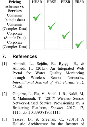
We now discuss suitable pricing schemes for above mentioned categories. If the user is a consumer (prepaid) who demands simple data services excluding audio, video or image content, the most suitable pricing scheme is HHSR where successful delivery of content is not ensured and payments are made to all entities on the basis of transmission of packets. If the user is a consumer (prepaid) who demands simple and complex data, the most suitable pricing scheme is HRSR where transmission is ensured by retransmissions by each entity involved. In case of complex contents, the user is charged more and thus extra amount is reimbursed for retransmission attempts in case of delivery failure.
If the user is a corporate (postpaid) customer and demands simple data with ensured data delivery, EESR is most suitable pricing scheme. The corporate customer, when demanding simple data, pays only if data delivery is successful. On the other hand, when complex data is demanded and payments are made accordingly, retransmission attempts are reimbursed to the involved entities ensuring 100% delivery of data
Source Destination
If packet arrives then send reimbursement R
R R
R
Source
R
Destination
with enhanced quality of service. Most suitable pricing scheme in this case is ERSR. This discussion is summarized in Table 2.
6. Conclusion
Presently WSN services are not common among general public due to lack of simple access mechanisms and service means. These services although beneficial and important are not fully and accessibly commercialized. Some important elements in quality of service assurance are caching techniques, location based query resolution, security and privacy implementation. A complete business model is also presented that reflects the role and benefits of each involved entity. SNS architecture along with its business model is a promising revolution in the world of WSN service provision in terms of rapid, acceptable and convenient commercialization. In future, commercialization of WSN services could be extended towards provision of these services through mobile network operators. This work can serve as a guideline for mobile network operators in order to plan and launch WSN services for their customers.
Table 2: Evaluation of Pricing Schemes with
respect to Services
Pricing schemes vs.
Services
HHSR HRSR EESR ERSR
Consumer (simple data)
Consumer (Complex Data)
Corporate (Simple Data)
Corporate (Complex Data)
7. References
[1] Ahmedi, L., Sejdiu, B., Bytyçi, E., & Ahmedi, F., (2015). An Integrated Web Portal for Water Quality Monitoring through Wireless Sensor Networks. International Journal of Web Portals 7(1). 28-46.
[2] Guijarro, L., Pla, V., Vidal, J. R., Naldi, M, & Mahmoodi, T., (2017) Wireless Sensor Network-Based Service Provisioning by a Brokering Platform, Sensors 2017, 17, 1115. doi:10.3390/s17051115
[3] Tracey, D., & Sreenan, C., (2013) A Holistic Architecture for the Internet of
Things, Sensing Services and Big Data, IEEE/ACM CCGRID 2013, 546-553. [4] Rea, S., Aslam, M. S., & Pesch, D., (2013),
Serviceware - A Service Based Management Approach for WSN Cloud Infrastructures, IEEE MUCS, 133-138. [5] ISP Edge Design. (2006). White Paper,
Cisco® Press.
[6] Dohler, M., Vieux, C., & Cedex, M., (2008). Wireless Sensor Networks: The Biggest Cross-Community Design Exercise To-Date. Bentham Recent Patents on Computer Science.
[7] Hau, T., Burghardt, D., & Brenner, W., (2011). Multi-homing, content delivery networks, and the market for Internet connectivity. Telecommunications Policy 35. 532–542.
[8] Hasni, B., (2010). Novel Architecture of Routing and Data Dissemination for Commercially Deployed Wireless Sensor Networks. Masters Thesis KTH Sweden, 59 - 61.
[9] Kobialka, T., Buyya, R., Deng, P., Kulik, L., & Palaniswami, M., (2010). Sensor Web: Integration of Sensor Networks with Web and Cyber Infrastructure. Book Chapter, ISI Global USA.
[10] Lamparter, B., Paul, K., & Westhoff, D., (2003). Charging support for ad hoc stub networks. Computer Communications 26(13). 1504-1514.
[11] Nath, S., Liu, J., & Zhao, F., (2006). Challenges in Building a Portal for Sensors WorldWide. Microsoft Research, 2006. [12] Olla, P., & Patel, N. V., (2002). A value
chain model for mobile data service providers. Telecommunications Policy 26. 551–571.
[13] Rafique, M. Z., Yaqub, M. A., & Farooq, M., (2010). MESSIAH: To Nip the Exploits in the Bud. Technical Report (TR) nexGIN RC.
[14] Raza, M. T., Jeatek, R., Yoo, S., Kim, K., Joo, S., & Jeong, W., (2009) Design and Implementation of Architectural Framework for Web Portal in Ubiquitous Pervasive Environment. IEEE, CNSR, 4-16.
[15] Tsetsos, V., Alyfantis, G., Hasiotis, T., Sekkas, O., & Hadjiefthymiades, S., (2005). Commercial Wireless Sensor Networks:
Technical and Business Issues. WONS, Saint Moritz.
[16] Shams, S. M., & Engelstad, P. E., (2009). Analysis of Peer Selection Algorithms in Cross-Layer P2P Architectures. IMSAA, 2 - 5.
[17] Timmers, P., (1999). Business Models for Electronic Markets. Research Note (RN) Electronic Commerce.
[18] Wu, Y., Hande, P. H., Kim, H., Chiang, M., & Tsang, D. H. K., (2010). QoS-revenue tradeoff with time-constrained ISP pricing. Quality of Service (IWQoS), 18th International Workshop on. 1-9.
[19] Xi, Y., & Yeh, E. M., (2010). Pricing, competition, and routing in relay networks. Communication, Control, and Computing, 47th Annual Allerton Conference on. 507-514.