Sharif University of Technology
Scientia IranicaTransactions A: Civil Engineering http://scientiairanica.sharif.edu
Invited Paper
A new higher-order strain-based plane element
M. Rezaiee-Pajand
, N. Gharaei-Moghaddam, and MR. Ramezani
School of Engineering, Ferdowsi University of Mashhad, Mashhad, Iran.Received 3 March 2019; received in revised form 26 April 2019; accepted 20 May 2019 KEYWORDS
Strain-based formulation; Second-order strain eld;
Equilibrium condition; Numerical evaluation; Drilling degrees of freedom.
Abstract.This study proposes a new higher-order triangular plane element with drilling degrees of freedom by considering second-order strain eld. In addition to the inclusion of drilling degrees of freedom and utilization of higher-order assumes strains, the satisfaction of equilibrium equations improves the performance of the suggested element in comparison to many of the other available elements. Following the proposition of the new element, a series of benchmark problems are solved to evaluate the performance of the suggested element. Accuracy and eciency of the suggested element are compared with those of other strain-based plane elements. Detailed discussions are proposed after each benchmark problem. Finally, based on the attained results, a nal conclusion about the characteristics of robust membrane elements is made.
© 2019 Sharif University of Technology. All rights reserved.
1. Introduction
Numerical methods are proved to be powerful and eec-tive computational tools for the analysis of complicated and practical engineering problems. Various numerical approaches were developed in the past decades such as the nite element method, nite dierence technique, boundary element method, and discrete element ap-proach. Among these techniques, the nite element method has obtained greater popularity due to its strong mathematical bases and inherent capabilities. Accordingly, various formulation techniques were de-veloped in the past decades, and there are thousands of nite elements available to analyze dierent types of problems and structures. Among the available approaches to nite element formulation, the most
well-*. Corresponding author. Tel./Fax: +98 51 38412912 E-mail addresses: [email protected] (M. Rezaiee-Pajand); [email protected] (N. Gharaei-Moghaddam); [email protected] (MR. Ramezani) doi: 10.24200/sci.2019.21429
known and widely applicable one is the displacement-based technique. This method, sometimes known with dierent terms, such as the classical or stiness approach, is the rst scheme that is used for the development of nite elements [1]. Clear and straight-forward process and applicability to dierent types of problems and structures are the prominent advantages of the displacement-based formulation for structural and mechanical applications. However, this process has various shortcomings. For instance, inaccuracy and discontinuity of stresses, which are secondary parame-ters in the stiness approach, represent vital deciency in structural applications, where stress is a decisive parameter in the design practice. Another common problem of displacement-based nite elements includes various locking phenomena, such as shear and mem-brane locking, which necessitate special treating, often requiring considerable time and eort and reducing the eciency of the method [2,3]. Moreover, in severely nonlinear problems, the displacement-based elements usually necessitate utilizing very ne meshes, which are inappropriate in terms of eciency. To remedy the mentioned and other shortcomings of the displacement
approach, other nite element formulations, such as the force-based, hybrid or mixed, assumed stress, and assumed strain, have been developed. Fortunately, these new procedures have their own advantages and shortcomings. For example, the force-based formula-tion performs very well in the linear and nonlinear analyses of frame structures and, also, provides an appropriate platform for the development of advanced frame elements [4-8]. Of note, the force formulation approach is limited to skeletal structures, and its application to continuous structures is very dicult if not possible. Despite the fact that each method has dierent merits and limitations, some approaches have received greater attention from researchers, while others have been almost overlooked. One of these techniques that has received less attention despite its promising performance is the strain-based or assumed strain approach. It is proved that the strain-based approach is very eective in removing problems such as shear parasitic error, mesh sensitivity, and dierent locking phenomena. Various authors have utilized this scheme to develop strain-based plane elements [9-26]. Sabir is one of the pioneers of the development of strain formulation. In his early work, he proposed triangular and quadrilateral elements by assuming linear strain elds [9]. In another work, Sabir and Sfendji proposed four-node triangular and rectangular elements by assuming the linear normal strains and constant shear strain [10]. In 2003, Tayeh developed new strain-based triangular and rectangular elements using a higher-order incomplete second-order eld for the element [11]. Belarbi and Bourezane proposed a new element by incorporating Poisson's ratio in the assumed strain eld [12]. Belarbi and Bourezane performed another study in 2005 and proposed a triangular strain-based element with the geometry similar to their previous work, yet with a dierent strain eld [13]. In 2005, Belarbi and Maalem sug-gested an improved strain-based rectangular element by considering linear normal strains and constant shear strain [14]. The rst generalized quadrilateral plane element, whose strain eld satises both compatibility and equilibrium conditions, was proposed by Pajand and Yaghoobi [15]. In another study, Rezaiee-Pajand and Yaghoobi investigated the performance of two special rectangular variants of the previous element [16]. A four-node rectangular strain-based element with incomplete fourth-order normal strains was proposed by Rebiai and Belounar [17]. Rezaiee-Pajand and Yaghoobi proposed a ve-node triangular element with a complete linear strain eld [18]. To propose a new nite element, they utilized the complete linear strain eld of the previous study, yet with an element of dierent geometry [19]. In another research work, Rebiai and Belounar suggested a variant of their previous element [20]. They considered the strain eld
of their previous study [17], yet added a new linear term to the shear strain and changed the dependent term of the normal strains. Following his previous research studies, Rebiai et al. suggested a new strain-based quadrilateral element for linear dynamic analysis of the plane problems [21]. In an attempt to develop second-order strain-based elements, Rezaiee-Pajand and Yaghoobi proposed two quadrilateral strain-based elements with seven and nine nodes [22]. In 2016, Hamadi et al. independently proposed a new quadrilat-eral nite element [23]. This element is exactly similar to the element previously proposed by Rezaiee-Pajand and Yaghoobi in 2012 [15]. In order to analyze geomet-rically nonlinear plane structures, Rezaiee-Pajand and Yaghoobi modied their ve-node quadrilateral ele-ment [15] by the co-rotational approach [24]. In a more recent attempt to propose a three-node nine-degree-of-freedom triangular element, Rebiai suggested a new strain-based element with an incomplete second-order strain eld [25]. Rezaiee-Pajand carried out various studies to improve the performance of the strain-based nite elements. In one of the most recent studies, He and Gharaei-Moghaddam and Ramezani suggested new triangular elements [26]. Moreover, they also imposed the equilibrium condition to specify the dependent strain states. In addition to the mentioned plane elements, advantages of strain formulation persuade researchers to make use of this approach to develop nite elements of other types of structures [27-42].
A review of the existing strain-based plane el-ements shows that there is no membrane element with a complete second-order assumed strain eld, despite the fact that the application of higher-order elds leads to highly accurate estimation. Moreover, it is known that the use of complete strain elds in element formulation guarantees locking-free behavior for strain-based elements [15]. Therefore, in the present study, a new second-order strain-based element is proposed to investigate the eect of higher-order strain states and a new distribution model for degrees of freedom on the accuracy of the resulting element. The mentioned benchmark problems are resolved using the new element. Based on the obtained results by the suggested element and the reviewed membrane elements, a short discussion is provided after each problem. The attained results can be used to detect the most suitable assumptions and congurations to achieve a robust plane nite element.
2. Basics of the formulation
The main idea of the assumed strain formulation is to approximate the strain eld of the element with an assumed mathematical function. Polynomial Taylor expansion is a common choice for the assumed function. In the case of plane problems, the strain eld consists of
8 > > > < > > > :
"x(x; y) = ("x)0+ ("x;x)0x + ("x;y)0y + ("x;xx)0
x2
2
+ ("x;xy)0(xy) + ("x;yy)0
y2
2
+ ::: "y(x; y) = ("y)0+ ("y;x)0x + ("y;y)0y + ("y;xx)0
x2
2
+ ("y;xy)0(xy) + ("y;yy)0
y2
2
+ ::: xy(x; y) = (xy)0+ (xy;x)0x + (xy;y)0y + (xy;xx)0
x2
2
+ (xy;xy)0(xy) + (xy;yy)0
y2 2 + ::: (1) Box I
three components, namely "x, "y, and xy. According
to the concept of Taylor expansion, each of the strain components can be approximated by a polynomial function of arbitrary order in the form of Eq. (1) shown in Box I. Choosing the higher-order terms of Taylor expansion for the assumed strain eld would increase convergence speed and accuracy of the suggested el-ement and, yet, reduce its numerical eciency due to the addition of more degrees of freedom to the element. Despite the application of dierent criteria, such as pure plain bending test, for choosing the higher-order terms for strain components, there is no required condition for this selection, and the only necessity is to include constant terms in the assumed strain eld. However, like the classical displacement-based formulation, it is advised not to assign priority to any of the coordinates (x or y). Moreover, it is possible to select strain components of specic order according to the knowledge of analytic form of the strain eld.
In any case, when the desired terms are chosen for the strain components, it is possible to apply any preferred optimized condition to the assumed strain eld. These optimized criteria provide necessary or fa-vorite properties for the element strain eld. The most common criteria include compatibility and equilibrium conditions. Based on the plane elasticity principle, the compatibility of the strain eld is satised, provided that the following relationship is established between the strain components:
@2" x
@y2 +
@2" y
@x2 =
@2 xy
@x@y: (2)
The other common optimized condition is equilibrium. The equation of equilibrium for the plane problems is dened as follows:
(
@x
@x +@@yxy + Fx= 0
@y
@y +@@yxy + Fy = 0
(3) where Fx and Fy are the body forces in x and y
directions, respectively. x, y, and xy are normal
and shearing stresses, respectively. To rewrite the equilibrium equation in terms of strain, it is necessary to relate the stresses to the strains. For the plane problems, the coming relations connect stresses and strains to each other:
8 > < > :
x= 2G"x+ ("x+ "y)
x= 2G"y+ ("x+ "y)
xy= Gxy
(4) is called the Lame constant and is equal to E
(1+)(1 )
for the plane stress condition. In the case of plane strain, this constant is equal to E
(1+)(1 2). E, G, and
are the modulus of elasticity, shear modulus, and Poisson's ratio, respectively. Substituting Eq. (4) in the equilibrium equation results in the following relations:
(
(2G + )@"x
@x + @"@xy + G@@yxy + Fx= 0
@"x
@y + (2G + )@"@yy + G@@xxy + Fy = 0
(5) The inclusion of the optimized condition makes some of the strain states dependent on the other ones. When the dependent strain states are determined, the assumed strain eld is rewritten in terms of the independent ones. The next step is to calculate the associated displacement eld. For this purpose, the strain-displacement formulae are utilized:
8 > > < > > :
"x=@u@x
"y= @v@y
"x=12
@u
@y +@v@x
(6)
In these relations, u and v are displacements in x and y directions, respectively. Based on these equalities, the displacements in x and y directions are derived by integrating normal strain components with respect to their associated coordinates:
(
u(x; y) =R"xdx + f1(y)
v(x; y) =R "ydx + f2(y) (7)
In these equations, f1 and f2 are derived by
inte-grating shear strain with respect to the coordinates and imposing necessary conditions of the rigid body modes. For a plane problem, there are three rigid body modes in the displacement eld, namely uo, vo,
and ro, standing for rigid body displacements in x
and y directions and rigid body rotation, respectively. According to the displacement-based formulation, the existence of these terms is a necessary condition to guarantee the convergence of the resulting nite ele-ment. Therefore, these modes are also counted among
the independent strain states that can be arranged in a vector arrangement indicated by S. This vector is called strain state vector. By using the matrix notation which is traditionally used in nite element formulation in structural engineering applications, it is possible to relate the displacement and strain elds to the strain state vector in the subsequent forms:
U = NS:S + eU; (8)
" = BS:S + e"; (9)
where NS and BS are displacement and strain
inter-polation matrices, respectively. ~U and e" are particular part of the displacement and strain elds that depend on the body forces. The element nodal displacements can be computed by substituting coordinates of the element nodes in the displacement eld. Thus, the fol-lowing relation can be established between the vectors of nodal displacements and the strain states:
D = A:S + eD = D + eD: (10)
In this equation, D and eD are the nodal displacement vectors due to body forces. A is the geometric matrix, which consists of the nodal displacement interpolation matrices of the element. By considering Eq. (10), it is possible to construct the succeeding relations between the displacement and strains elds of the element with the nodal displacement vector:
U = NS:S + eU = NS: A 1:D+ eU
= NS:A 1D + eU = N:D + eU; (11)
" = BS:S + e" = BS: A 1:D+ e"
= BS:A 1D + e" = B:D + e": (12)
Because the body forces are usually negligible in comparison with the applied loads, the strains and dis-placements due to body forces, e" and eU, are neglected. The last step in the formulation of the nite element scheme is to derive the element stiness matrix and the nodal force vector. There are dierent ap-proaches to nding the stiness matrix of an element. For instance, it is possible to utilize the total potential energy principle. This functional can be written as follows:
= 1 2
Z
T"dv Z UTF dv DTP
ext: (13)
In this relation, Pext and F are the applied external
nodal and body forces, respectively. To derive the element stiness matrix and nodal force vector, it is required to establish a stationary of the functional:
@ @D =A T
Z BT
S:Dm:BSdv
A 1:D
A TZ NT S:F dv
Pext=KD P =0: (14)
Accordingly, the element stiness matrix and nodal force vector are derived as follows:
K =A TZ BT
S:Dm:BSdv
A 1=A T:K
0:A 1;
(15) P = Pext+ A T
Z NT
S:F dv
; (16)
where Dmis the material matrix:
Dm=1 E 2
2
4 1 1 00
0 0 1
2
3
5 : (17)
3. Element formulation
To propose a new strain-based membrane element, it is assumed that the normal strains have complete second-order eld, while the shear strain is approximated using a linear eld as shown in Box II.
It is proved that the imposition of compatibility and equilibrium conditions on the assumed strain eld results in a more accurate element with a faster convergence trend [15]. Moreover, this action reduces the number of independent strain states in the element strain eld. The number of independent strain states species the number of required degrees of freedom; therefore, their reduction results in an element with fewer degrees of freedom, which is more desirable from a numerical eciency standpoint. Accordingly, enforcing the compatibility and equilibrium criteria on the assumed strain eld of Eq. (18) (shown in Box II)
8 > > < > > :
"x(x; y) = ("x)0+ ("x;x)0x + ("x;y)0y + ("x;xx)0
x2
2
+ ("x;xy)0(xy) + ("x;yy)0
y2
2
"y(x; y) = ("y)0+ ("y;x)0x + ("y;y)0y + ("y;xx)0
x2
2
+ ("y;xy)0(xy) + ("y;yy)0
y2
2
xy(x; y) = (xy)0+ (xy;x)0x + (xy;y)0y
(18)
results in the subsequent dependent strain states: 8 > > > > > > > > > > < > > > > > > > > > > :
("y;xy)0= 0
("y;xx)0= ("x;yy)0
(xy;y)0= 2G+G ("x;x)0 G("y;x)0
(xy;x)0= 2G+G ("y;y)0 G("x;y)0
("x;xy)0= 2G+ ("y;xy)0
("y;yy)0= 2G+ ("x;yy)0
("x;xx)0= 2G+ ("x;yy)0
(19)
The assumed strain eld in Eq. (18) consists of fteen strain states, which, in addition to three rigid body modes, results in a total of eighteen strain states. As presented by Eq. (19), seven of these strain states are dependent on the others; therefore, the element strain state vector consists of eleven constituents as follows:
S =
u0 v0 r0 ("x)0 ("y)0 (xy)0 ("x;x)0 ("x;y)0
("y;x)0 ("y;y)0 ("x;yy)0
(20) where uo, vo, and ro are the rigid body motions.
By using this vector, the assumed strain eld of the element can be rearranged in the succeeding matrix notations:
" = BS:S; (21)
where the strain interpolation matrix, BS, is dened
by Eq. (22) as shown in Box III.
By utilizing the strain-displacement relations and performing integration of the strain components, the element displacement eld in terms of independent strain states and rigid body modes is obtained. The displacement eld can be reported using matrix nota-tions:
U = NS:S; (23)
where the displacement interpolation matrix is pre-sented by Eq. (24) as shown in Box IV. The next step of the formulation is to select element geometry and degrees of freedom.
First of all, it is required to determine the ge-ometry of the element. Since many of the available plane elements formulated by various methods are quadrilateral, it is preferred to suggest robust triangu-lar element. Moreover, triangutriangu-lar geometry facilitates meshing of structures of dierent shapes. Regarding the type of the degrees of freedom, for the new element, both translational and drilling degrees of freedom will be used. It is well known that the addition of drilling degrees of freedom to membrane elements is benecial because of three main reasons: (a) It facilitates the development of shell elements and connection of shell and membrane element to beam elements, (b) The drilling degrees of freedom can be added to the element without the necessity of adding new mid-side nodes, and (c) It is eortless to include these extra degrees of freedom in the commercial nite element programs, which usually can carry six degrees of freedom per node [43]. Moreover, various studies showed that, in addition to the mentioned advantages, using drilling degrees of freedom improved the performance of mem-brane elements, especially under bending loads [44-48], and this is the main reason for using drilling degrees of freedom in the formulation of the new strain-based ele-ment in the present study. However, since the author's goal is to investigate eects of node distribution and the type of degrees of freedom on the performance of strain-based element, the second mentioned advantage of using drilling degrees of freedoms is violated and, instead, drillings are considered for new mid-side nodes. This assumption results in a new element conguration, which is not treated previously by researchers. This element is demonstrated in Figure 1. As can be seen, the element had seven nodes and eleven degrees of freedom in agreement with the independent strain
BS =
2 6 4
0 0 0 1 0 0 x y 0 0 y22 + x2
2(2G+)
0 0 0 0 1 0 0 0 x y x2
2 + y
2
2(2G+)
0 0 0 0 0 1 (2G+)yG
Gx Gy (2G+)xG 0
3 7
5 : (22)
Box III
NS =
2
41 0 y x 0 y2 x
2
2 (2G+)y
2
2G xy y2 G+2G
0 x3
6
2G+
+xy2
2
0 1 x 0 y x
2 0 x2 G+2G
xy y2
2 (2G+)x 2 2G y 3 6 2G+ +yx2
2
3 5 :
(24) Box IV
Figure 1. Seven-node triangular element with an incomplete second-order strain eld.
states. The nodal displacement vector can be written as follows:
D =D2i 1 D2i D2j 1D2j D2k 1 D2k Dl Dm
Dn D2p 1 D2p T: (25)
The drilling degree of freedom is related to displace-ment components by the following equation:
= 1 2
@v @x
@u @y
: (26)
Therefore, it is possible to calculate drilling in terms of strain states vector as shown in Box V. The required quantity for the element formulation is the geometric matrix. According to Figure 1 and the selected degrees of freedom, the geometric matrix of this element is derived from the subsequent relation:
A=Nsi Nsj Nsk Tsl Tsm Tsn NspT:(29)
Now, the element stiness matrix and the vector of nodal forces can be computed by Eqs. (15) and (16). The accuracy and eciency of the suggested element
will be evaluated in the following section using a series of well-known benchmark problems. Moreover, the attained results reported by other researchers who proposed assumed strain membrane elements are also presented to provide an opportunity for comparison. 4. Numerical evaluation
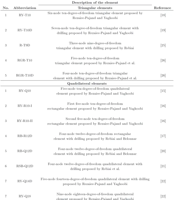
In this section, a series of benchmark problems are solved to evaluate the performance of the suggested element. Table 1 presents a list of the strain-based elements used for comparison. In addition to the listed elements, results of the three common displacement-based elements, namely four-node and eight-node isoparametric quadrilateral elements (Q4 and Q8) and Linear Strain Triangular element (LST), are provided in some problems to compare the performance of the strain-based formulation with them.
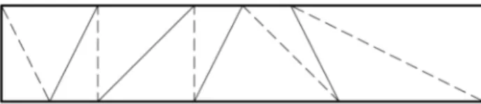
4.1. Cantilever beam with distorted mesh One of the available tests to examine the performance of the membrane elements in coarse distorted meshes under both bending and shear loadings is the cantilever beam, which is depicted in Figure 2.
This gure illustrates the geometric character-istics, loading, and utilized meshes for quadrilateral elements. The modulus of elasticity and Poisson's ratio of this beam are 1500 and 0.25, respectively, and its thickness is equal to 1. The utilized mesh for analysis using triangular elements is demonstrated in Figure 3.
Figure 2. Cantilever beam with distorted quadrilateral mesh.
Figure 3. Triangular mesh for analysis of cantilever beam with distorted mesh.
= Ts:S; (27)
Ts=
h
0 0 1 0 0 0 (2G+)y2G (2G+)x2G (2G+)y2G (2G+)x2G xyi: (28)
Table 1. List of the plane elements used for comparison. Description of the element
No. Abbreviation Triangular elements Reference
1 RY-T10 Six-node ten-degree-of-freedom triangular element proposed by
Rezaiee-Pajand and Yaghoobi [18]
2 RY-T10D Seven-node ten-degree-of-freedom triangular element with
drilling proposed by Rezaiee-Pajand and Yaghoobi [19]
3 R-T9D Three-node nine-degree-of-freedom
triangular element with drilling proposed by Rebiai [25]
4 RGR-T10 Five-node ten-degree-of-freedom
triangular element proposed by Rezaiee-Pajand et al. [26] 5 RGR-T10D Four-node ten-degree-of-freedom triangular
element with drilling proposed by Rezaiee-Pajand et al. [26] Quadrilateral elements
1 RY-Q10 Five-node ten-degree-of-freedom quadrilateral
element proposed by Rezaiee-Pajand and Yaghoobi [15] 2 RY-R10-I First ve-node ten-degree-of-freedom
rectangular element proposed by Rezaiee-Pajand and Yaghoobi [16] 3 RY-R10-II Second ve-node ten-degree-of-freedom
rectangular element proposed by Rezaiee-Pajand and Yaghoobi [16] 4 RB-R12D Four-node twelve-degree-of-freedom rectangular
element with drilling proposed by Rebiai and Belounar [17] 5 RB-Q12D Four-node twelve-degree-of-freedom quadrilateral
element with drilling proposed by Rebiai and Belounar [20] 6 RSB-Q12D Four-node twelve-degree-of-freedom quadrilateral element with
drilling proposed by Rebiai et al. [21] 7 RY-Q14D Five-node fourteen-degree-of-freedom quadrilateral element with drilling
proposed by Rezaiee-Pajand and Yaghoobi [22] 7 RY-Q18 Nine-node eighteen-degree-of-freedom quadrilateral
element proposed by Rezaiee-Pajand and Yaghoobi [22]
As evident, each quadrilateral element is divided by a dashed line to two triangular elements.
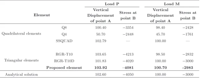
The attained results by the proposed element and other elements for deection of point A and normal stress at point B are listed in Table 2.
In fact, this test measures the performance of dierent elements to analyze structures with distorted meshes under bending and shear loading conditions.
According to the results, the proposed strain-based element provides acceptable accuracy. The results were obtained by RGR-T10 and RGR-T10D with the same assumed strain eld, and their dierence was only observed in terms of distribution. The type of degrees of freedom veries this conjecture including drilling degrees of freedom in the plane elements and improves their performance under in-plane bending.
Table 2. Deection of point A and stress at point B of the cantilever beam with distorted mesh.
Load P Load M
Element
Vertical Displacement
of point A
Stress at point B
Vertical Displacement
of point A
Stress at point B
Quadrilateral elements
Q8 100.40 3354 98.40 2428
Q4 50.70 2448 45.70 1761
SSQUAD 102.79 | 100.00 |
Triangular elements
RGR-T10 103.65 4213 98.50 2832
RGR-T10D 101.83 4020 100.00 3000
Proposed element 103.92 {4081 100.70 -2983
Analytical solution 102.60 4050 100.00 3000
4.2. Cantilever beam under parabolic shear loading
To investigate the performance of the elements in ana-lyzing structures under distributed surface traction, the cantilever beam demonstrated in Figure 4 is analyzed. This beam is made of elastic material with modulus of elasticity and Poisson's ratio equal to 3000 and 0.25, respectively, and its thickness is taken to be 1 unit. The beam is loaded by parabolic distributed traction at its free end, which is equal to 40 units.
This benchmark problem evaluates the eciency of the elements in the analysis of structures using coarse meshes. As evident in Figure 4, the beam is discretized by four quadrilateral elements. In the case of triangular elements, eight elements are used in which the utilized mesh is demonstrated in Figure 5. However, results of some of the reviewed elements are reported for regular mesh.
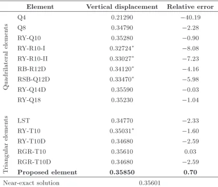
Table 3 presents the obtained responses by the mentioned membrane elements for deections at the
Figure 4. Cantilever beam under parabolic shear loading.
Figure 5. Triangular mesh for analysis of cantilever beam under parabolic shear loading.
tip of the beam. Felippa reported the near-exact tip deection of the beam equal to 0.35601 [49].
Based on the reported results, RGR-T10 and RY-Q14D are the most accurate elements in this problem with only 0.03% error in their estimations. The suggested element in this study is in the second place with less than 1% error.
4.3. Cook's skew beam
Cook trapezoidal beam is one of the most funda-mental tests for checking shear displacements in non-rectangular geometry. Figure 6 demonstrates this beam under uniformly distributed tip loading. This beam has unit thickness and is made of materials whose Young's modulus and Poisson's ratio are 1 and 1/3, respectively.
Many researchers have also implemented this
Table 3. Tip deection of cantilever beam under parabolic shear. Element Vertical displacement Relative error
Quadrilateral
elemen
ts
Q4 0.21290 40:19
Q8 0.34790 2:28
RY-Q10 0.35280 0:90
RY-R10-I 0.32724 8:08
RY-R10-II 0.33027 7:23
RB-R12D 0.34120 4:16
RSB-Q12D 0.33470 5:98
RY-Q14D 0.35590 0:03
RY-Q18 0.35230 1:04
T
riangular
elemen
ts LST 0.34770 2:33
RY-T10 0.35031 1:60
RY-T10D 0.34680 2:59
RGR-T10 0.35610 0.03
RGR-T10D 0.34680 2:59
Proposed element 0.35850 0.70
Near-exact solution 0.35601
The results are attained from a regular mesh.
Figure 7. Utilized meshes for analysis of Cook's skew beam.
benchmark to challenge the convergence of their el-ements. Here, four dierent meshes, namely meshes 22, 44, 88, and 1616, are used. These meshes are demonstrated in Figure 7. The results of the deection at point C are presented in Table 4. It should be noted that the near-exact solution to this problem is reported equal to 23.96 [49].
Outcomes of this problem are again in complete
Table 4. Deection of point C of the Cook's beam. Mesh
Element 2 2 4 4 8 8 16 16
Quadrilateral
elemen
ts Q4 11.80 18.29 22.08 23.43
RY-Q10 25.65 24.27 24.01 23.96 RB-Q12D 17.87 23.37 23.38 23.50 RY-Q14D 27.61 30.48 31.85 32.44 RY-Q18 23.45 23.70 23.86 23.92
T
riangular
elemen
ts RY-T10 20.94 23.84 24.18 24.13 RY-T10D 25.82 27.19 27.23 27.09 R-T9D 18.78 23.94 23.94 23.94 RGR-T10 21.18 23.03 23.69 23.95 RGR-T10D 19.06 22.85 23.14 23.87 RGR-T11D 26.00 24.39 24.01 23.97 Near-exact solution 23.96
agreement with the ndings of previous numerical ex-amples and, once more, the proposed element is among the best performing elements. The other elements that provide accurate estimations are RY-Q10, RGR-T10, and R-T9D. It is somehow unexpected that R-T9D is able to compute a very accurate response by a very coarse mesh of 4 4. As is evident, the convergence trend of dierent elements is not similar. While most
of the elements converge to the exact response asymp-totically from below, the proposed element approaches the accurate response from above. In addition, there are elements such as RY-T10 and RY-T10D that show non-uniform convergence behavior and, even, RY-Q14D goes beyond the response. Nevertheless, most of the strain-based elements demonstrate reasonable performance in this benchmark problem.
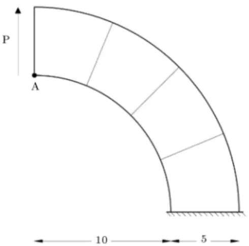
4.4. Thick curved beam
In order to appraise the ability of nite elements, especially triangular ones, to analyze curvy structures, many of the previous researchers have evaluated per-formance of their proposed element in the analysis of the curved beams, as demonstrated in Figure 8. This beam is loaded by the shear load P = 600 at its tip.
The modulus of elasticity, poison's ratio, and thickness of this beam are 1000, 0, and 1, respectively. As depicted in Figure 8, four quadrilateral elements are used to mesh this structure. In the case of triangular elements, eight elements are used, as demonstrated in Figure 9.
The exact vertical displacement of point A under
Figure 8. Thick curved beam with quadrilateral mesh.
Figure 9. The triangular mesh for analysis of thick curved beam.
Table 5. Deection of point A of thick curved beam. Load P
Element Vertical
displacement Relative error
Quadrilateral elemen
ts Q8 88.60 1:66
RY-Q10 86.92 3:53
RY-Q14D 87.00 3:44
RY-Q18 86.45 4:05
T
riangular elemen
ts
RY-T10 87.15 3:27
RY-T10D 87.47 2:92
RGR-T10 89.39 0:79
RGR-T10D 84.62 6:08
RGR-T11D 89.88 -0.24
Analytical solution 90.10
the applied load is equal to 90.10. The attained results by dierent elements are presented in Table 5. It is evident that the suggested element provides the most accurate estimation with only 0.24% error. After the proposed element, RGR-T10 with a relative error of 0.79% is in the second place. It is interesting to note that, among the quadrilateral elements, the performance of Q8 is better than those of the strain-based elements. Nonetheless, since the error of most of the strain-based elements is less than 5%, which is negligible by any set of standards for the utilized coarse mesh, this problem shows that the elements formulated by the assumed strain approach are suitable options for ecient analysis of curved structures and can compete with isoparametric elements.
4.5. Thin curved beam
To investigate the eect of shear lock in curved struc-tures and, also, the convergence rate to achieve a precise response, a thin curved beam test is available. This modulus of elasticity, poison's ratio, and thickness of this structure demonstrated in Figure 10 are 107, 0.25, and 0.1, respectively. This beam is loaded by a unit vertical force at its tip.
Three dierent meshes are used to analyze this structure, namely 1 6, 2 12, and 4 24. These meshes are named based on the number of quadrilateral elements used in them. Of note, to analyze using tri-angular elements, each quadrilateral element is divided into two triangular elements. For instance, 1 6 is demonstrated in Figure 11.
Figure 10. Thin curved beam.
Figure 11. The used 1 6 mesh for analysis of thin curved beam.
compute tip deection of the beam under applied load and, therefore, investigate the eect of locking problem on the performance of the strain-based elements. The exact vertical displacement at the tip is reported as equal to 0.08734 [15]. Table 6 presents the obtained results by some of the strain-based elements.
It is evident that the mentioned triangular el-ements, except the proposed one, face the locking problem in the coarsest mesh and behave too stiy. In contrast, the proposed element provides an acceptable response. In the coarsest mesh, the suggested element does not lock and only has 5.07% error. This error is reduced to 0.49% in the nest mesh. Of note, the quadrilateral elements provide more accurate estima-tions in the coarse mesh; however, they become a bit more exible in the nest mesh and, therefore, go beyond the exact solution.
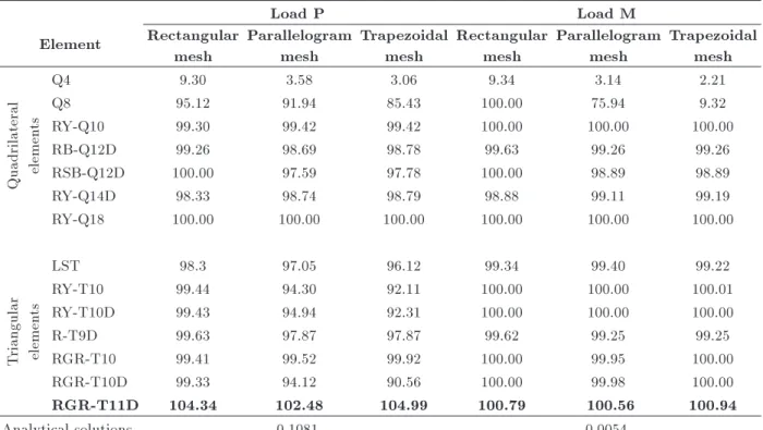
4.6. McNeal's beam
McNeal and Harder proposed this benchmark to ex-amine the sensitivity of the elements to the mesh dis-tortion and the trapezoidal locking phenomenon [46]. The geometry of this beam and the rectangular, paral-lelogram, and trapezoidal meshes used for analysis by quadrilateral elements are depicted in Figure 12. The utilized meshes for triangular meshes are demonstrated in Figure 13.
Modulus of elasticity, poison's ratio, and thickness of the structure are 107, 0.3, and 0.1, respectively. Two
modes of loading are assumed, as depicted in Figure 12. The derived responses by the strain-based elements are listed in Table 7.
This test is a dicult problem for many of the displacement-based membrane elements, since they demonstrate high sensitivity to trapezoidal meshes. For example, the powerful Q8 element with all of its capabilities faces fatal error for both modes of loading in trapezoidal mesh. However, as evident from the results presented in Table 7, most of the strain-based elements have no problem in this case.
4.7. Higher-order patch test
The beam, which is demonstrated in Figure 14, is the next numerical example that evaluates the performance of plane strain-based elements.
Table 6. Tip deection of thin curved beam. Mesh
Element 1 6 2 12 4 24
Deection Error Deection Error Deection Error
Quadrilateral elemen
ts RY-Q10 0:08901 1.91 0:08844 1.26 0:08846 1.28
RY-Q14D 0:08748 0.16 0:08898 1.87 0:08925 2.19
RY-Q18 0:08745 0.12 0:08840 1.21 0:08850 1.33
T
riangular elemen
ts RY-T10 0.05634 35:49 0.08491 2:78 0.08815 0.93
RGR-T10 0:06305 27:81 0:08493 2:76 0:08609 1:43
RGR-T10D 0:06486 25:74 0:08501 2:67 0:08650 0:96
RGR-T11D {0.08291 {5.07 {0.08434 {3.43 {0.08691 {0.49
Figure 12. McNeal's beam and utilized quadrilateral meshes. Table 7. Normalized tip deection of the McNeal's beam.
Load P Load M
Element Rectangular mesh
Parallelogram mesh
Trapezoidal mesh
Rectangular mesh
Parallelogram mesh
Trapezoidal mesh
Quadrilateral elemen
ts
Q4 9.30 3.58 3.06 9.34 3.14 2.21
Q8 95.12 91.94 85.43 100.00 75.94 9.32
RY-Q10 99.30 99.42 99.42 100.00 100.00 100.00
RB-Q12D 99.26 98.69 98.78 99.63 99.26 99.26
RSB-Q12D 100.00 97.59 97.78 100.00 98.89 98.89
RY-Q14D 98.33 98.74 98.79 98.88 99.11 99.19
RY-Q18 100.00 100.00 100.00 100.00 100.00 100.00
T
riangular elemen
ts
LST 98.3 97.05 96.12 99.34 99.40 99.22
RY-T10 99.44 94.30 92.11 100.00 100.00 100.01
RY-T10D 99.43 94.94 92.31 100.00 100.00 100.00
R-T9D 99.63 97.87 97.87 99.62 99.25 99.25
RGR-T10 99.41 99.52 99.92 100.00 99.95 100.00
RGR-T10D 99.33 94.12 90.56 100.00 99.98 100.00
RGR-T11D 104.34 102.48 104.99 100.79 100.56 100.94
Analytical solutions 0.1081 0.0054
Figure 13. The utilized triangular meshes for analysis of McNeal's beam.
This beam with a geometric ratio of 10 is made of elastic material with modulus of elasticity and Poisson's ratio equal to 100 and 0, respectively. The thickness of the beam is taken as 1. Two dierent types of meshes, namely regular and distorted, are demonstrated in Figure 15 and are used.
This test examines the performance of the el-ements under the pure bending and considering the
Figure 14. Higher-order patch test.
simple support conditions. The attained results by the strain-based elements are listed in Table 8. It is evident that, almost, all of the elements can compute the exact response regardless of the mesh type.
4.8. Thick-walled cylinder
The cylindrical plane strain test of the thick wall under uniform internal pressure is the eighth problem, which investigates the eect of Poisson's locking on the per-formance of strain-based elements. Due to symmetry,
Table 8. Maximum displacements of the higher-order patch test. Regular mesh Distorted mesh
Element Max U Max V Max U Max V
Quadrilateral elemen
ts
RY-Q10 {0.600 1.500 {0.600 1.500
RY-R10-I {0.600 1.500 {0.600 1.500
RB-R12D {0.600 1.500 {0.600 1.500
RB-Q12D {0.594 1.493 {0.592 1.484
RSB-Q12D {0.590 1.500 {0.590 1.490
RY-Q14D {0.600 1.500 {0.600 1.500
RY-Q18 {0.600 1.500 {0.600 1.500
T
riangular elemen
ts RY-T10D {0.600 1.500 {0.600 1.500
RGR-T10 {0.600 1.500 {0.600 1.500
RGR-T10D {0.600 1.500 {0.600 1.500
RGR-T11D {0.600 1.500 {0.600 1.500
Analytical solution {0.600 1.500 {0.600 1.500
Figure 15. Utilized regular and distorted meshes.
only a quarter of this cylinder will be analyzed. This structure and utilized mesh are depicted in Figure 16. The elastic modulus of the material is 1000, and it is solved for dierent values of Poisson's ratio varying
from 0.3 to 0.4999. The exact radial displacements of this cylinder under internal pressure can be computed through the following relation [50]:
ur= (1 + )pR 2 in
E(R2
ex Rin2 )
Rex
r + (1 2)r
; (30)
where Rinand Rexare the internal and external radii of
the cylinder. The derived results by dierent elements are presented in Table 9. According to the outcomes, the assumed strain approach results in elements free from Poisson's locking.
4.9. Theoretical slender beam
The beam depicted in Figure 17 with a length of 100 is made of elastic material with Young's modulus and Poisson's ratio equal to 106 and 0.3, respectively. This structure is used to investigate the shear eect on the slender plane problems.
This structure is analyzed using two dierent meshes. The obtained results for tip displacements of
Table 9. Normalized radial displacement of the thick walled cylinder at the inner radius. Poisson's ratio
Element 0.3 0.49 0.499 0.4999
Quadrilateral elements RY-Q14DRY-Q10 0.97991.1805 0.97891.1839 0.97901.1841 0.97941.1846 RY-Q18 0.9360 0.9576 0.9593 0.9599 Triangular elements RGR-T11D 1.01869 1.0356 1.0361 1.0365 Analytical solution 0.00506 0.00506 0.00504 0.00458
Figure 17. Extremely slender cantilever beam.
the beam are listed in Table 10. The proposed element and RGR-T10 have the best performance among the reported elements. It is evident that Q4 suers from
Table 10. Tip displacements of slender cantilever beam. Displacements
Element Mesh Ux 100 Uy
Quadrilateral
elemen
ts
Q4 1 100 2.0222 2.6965
2 200 2.1280 2.8371
RY-Q10 1 100 3.0046 4.0067
2 200 2.9991 3.9982 RY-R10-I 1 100 3.0046 4.0067 2 200 2.9991 3.9982 RY-R10-II 1 100 3.0000 4.0002 2 200 2.9987 3.9976 RY-Q14D 1 100 3.0000 4.0067 2 200 3.193 4.2581
RY-Q18 1 100 2.9983 3.9967
2 200 2.9989 3.9980
T
riangular
elemen
ts
RY-T10 1 100 3.0000 4.0001
2 200 2.9992 3.9986 RGR-T10 1 100 3.0000 4.0000 2 200 3.0000 4.0000 RGR-T10D 1 100 2.9845 3.9767 2 200 2.9944 3.9975 RGR-T11D 1 100 3.0001 4.0003
2 200 3.0001 4.0001
Analytical solution 3 4
locking problem and, therefore, cannot compute exact response even using a ne mesh.
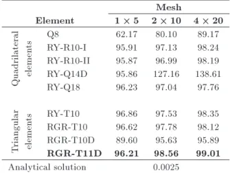
4.10. Cantilever shear wall
An important purpose of formulating ecient elements is to analyze practical structures with minimal ele-ments. Therefore, in order to investigate the eciency of the strain-based elements in practical problems, two shear walls are examined with the proposed element and the other strain elements. In the rst problem, the shear wall, which is shown in Figure 18, is analyzed.
The modulus of elasticity and Poisson's ratio of the wall are 2 107 and 0.2, respectively. Here,
to reevaluate the accuracy and eciency of strain formulation, as well as the potency of the proposed
Table 11. Lateral displacement of the top of the shear wall.
Mesh
Element 1 5 2 10 4 20
Quadrilateral elemen
ts Q8RY-R10-I 62.1795.91 80.1097.13 89.1798.24
RY-R10-II 95.87 96.99 98.19 RY-Q14D 95.86 127.16 138.61 RY-Q18 96.23 97.04 97.76
T
riangular elemen
ts RY-T10 96.86 97.53 98.35
RGR-T10 96.62 97.78 98.12 RGR-T10D 89.60 95.63 95.89 RGR-T11D 96.21 98.56 99.01 Analytical solution 0.0025
element, the conventional element Q8 is brought for comparison. Further, to investigate the convergence, two ner meshes have been used. The normalized responses are provided in Table 11.
Based on the results presented in Table 11, the suggested element demonstrates the best performance among the compared elements. Two interesting out-comes include lower accuracy of Q8 and inability of
RY-Q14D, which becomes too exible when using ner meshes. As can be observed, all of the reported strain-based elements except RGR-T10D have less than 5% error in their estimations when a coarse 1 5 mesh is used. This nding again demonstrates the high eciency of the assumed strain approach.
4.11. Shear wall with opening
In the last numerical example, a coupled shear wall is scrutinized to study the performance of the elements in the presence of opening. This structure, which is depicted in Figure 19, is made of elastic material with modulus of elasticity and Poisson's ratio equal to 2 107 and 0.2, respectively. The thickness of this
structure is assumed 0.4. Lateral loads with intensity of P = 500 is applied to each story level of the left shear wall. The structure is analyzed by two meshes consisting of 48 and 192 quadrilateral elements (96 and 384 triangular elements). To achieve the near-exact solution, the coupled wall is analyzed by 26880 eight-node isoparametric elements (Q8). The obtained results for lateral displacements at dierent story levels are reported in Table 12.
It is evident that the suggested element provides the most accurate estimations. Based on the
re-Table 12. Lateral story displacements of the coupled shear wall. Lateral displacement
Element Number of
elements Story 2 Story 4 Story 6 Story 8
Quadrilateral
elemen
ts
Q8 192 elements48 elements 0.560.68 1.531.82 2.593.02 3.644.16
RY-R10-I 48 elements 0.77 2.07 3.40 4.71
192 elements 0.78 2.07 3.44 4.71
RY-R10-II 48 elements 0.69 1.88 3.13 4.28
192 elements 0.74 2.00 3.32 4.65
RY-Q14D 192 elements48 elements 0.901.14 2.623.22 4.615.49 6.637.70
RY-Q18 48 elements 0.76 2.03 3.36 4.61
192 elements 0.80 2.13 3.51 4.81
T
riangular
elemen
ts
RY-T10 192 elements48 elements 0.710.80 1.922.12 3.183.50 4.384.79
RGR-T10 48 elements 0.76 2.03 3.29 4.54
192 elements 0.85 2.26 3.63 4.96
RGR-T10D 48 elements 0.73 1.94 3.19 4.45
192 elements 0.82 2.14 3.55 4.86
RGR-T11D 192 elements48 elements 0.750.83 2.072.25 3.263.56 4.635.02
Figure 19. The coupled shear wall and the utilized meshes.
ported results for Q8 element, most of the strain-based membrane elements are more accurate and ecient. However, there is an exception about RY-Q14D, which becomes too exible by using ner meshes and fails to converge to the exact response.
5. Conclusion
This study proposed a new triangular strain-based element with a second-order assumed strain eld. Then, a series of well-known benchmark problems were solved using the proposed element and some of the other existing membrane elements and common displacement-based elements such as Q4, Q8, and LST. The obtained results clearly demonstrated the superiority of the strain-based formulation in accuracy and eciency against displacement-based membrane elements. Various problems such as mesh sensitivity, shear, trapezoidal, and Poisson's locking were investi-gated, and the attained results showed that almost all of the plane elements formulated by the assumed strain approach were free from these shortcomings and could even compute response practical problems using coarse mesh of elements. Therefore, the strain-based elements completely t with the denition of robust nite el-ements. It must be added that the newly proposed triangular plane element is among the best performing elements in all of the analyzed benchmark problems. This shows the merit of using higher-order assumed strain elds and imposing equilibrium equation on the opted strain components. The mentioned advantages make the assumed strain formulation an interesting alternative for developing robust nite elements of dierent types.
References
1. Zienkiewicz, O.C. and Taylor, R.L., The Finite El-ement Method for Solid and Structural Mechanics, Elsevier (2005).
2. Hughes, T.J.R., Taylor, R.L., and Kanoknukulchai, W. \A simple and ecient nite element for plate bending", Int. J. Numer. Meth. Eng., 11(10), pp. 1529-1543 (1977).
3. Reddy, J.N., An Introduction to the Finite Element Method, New York, USA: McGraw-Hill (1993).
4. Rezaiee-Pajand, M. and Gharaei-Moghaddam, N. \Analysis of 3D Timoshenko frames having geometri-cal and material nonlinearities", Int. J. of Mech. Sci., 94, pp. 140-155 (2015).
5. Rezaiee-Pajand, M. and Gharaei-Moghaddam, N. \Frame nonlinear analysis by force method", Int. J. Ste. Str., 17(2), pp. 609-629 (2017).
6. Rezaiee-Pajand, M. and Gharaei-Moghaddam, N. \Us-ing co-rotational method for cracked frame analysis", Meccanica, 53(8), pp. 2121-2143 (2018).
7. Rezaiee-Pajand, M. and Gharaei-Moghaddam, N. \Force-based curved beam elements with open radial edge cracks", Mech. Adv. Mater. Struc., pp. 1-13 (2018). DOI: 10.1080/15376494.2018.1472326
8. Rezaiee-Pajand, M. and Gharaei-Moghaddam, N. \Vi-bration and static analysis of cracked and non-cracked non-prismatic frames by force formulation", Eng. Str., 185, pp. 106-121 (2019).
9. Sabir, A.B. \A rectangular and triangular plane elas-ticity element with drilling degrees of freedom", 2nd Int. Conf. on Var. Meth. in Engrg., Southampton, UK, pp. 17-25 (1985).
10. Sabir, A.B. and Sfendji, A. \Triangular and rectan-gular plane elasticity nite elements", Thin. Wall. Struct., 21(3), pp. 225-232 (1995).
11. Tayeh, S.M., New Strain-Based Triangular and Rect-angular Finite Elements for Plane Elasticity Problems, The Islamic University of Gaza (2003).
12. Belarbi, M.T. and Bourezane, M. \On improved Sabir triangular element with drilling rotation", Rev. Europ. Gen. Civ., 9(9-10), pp. 1151-1175 (2005).
13. Belarbi, M.T. and Bourezane, M. \An assumed strain based on triangular element with drilling rotation", Cour. Sav., 6, pp. 117-123 (2005).
14. Belarbi, M.T. and Maalem, T. \On improved rectan-gular nite element for plane linear elasticity analysis", Rev. Europ. Elem., 14(8), pp. 985-997 (2005).
15. Rezaiee-Pajand, M. and Yaghoobi, M. \Formulating an eective generalized four-sided element", Eur. J. Mech. A-Solid, 36, pp. 141-155 (2012).
16. Rezaiee Pajand, M. and Yaghoobi, M. \A free of parasitic shear strain formulation for plane element", Res. Civ. Env. Eng., 1, pp. 1-24 (2013).
17. Rebiai, C. and Belounar, L. \A new strain based rectangular nite element with drilling rotation for linear and nonlinear analysis", Arch. Civ. Mech. Eng., 13(1), pp. 72-81 (2013).
18. Rezaiee-Pajand, M. and Yaghoobi, M. \A robust triangular membrane element", Lat. Amer. J. Sol. Struc., 11(14), pp. 2648-2671 (2014).
19. Rezaiee-Pajand, M. and Yaghoobi M. \An ecient for-mulation for linear and geometric non-linear membrane elements", Lat. Amer. J. Sol. and Struc., 11(6), pp. 1012-1035 (2014).
20. Rebiai, C. and Belounar, L. \An eective quadri-lateral membrane nite element based on the strain approach", Measurement, 50, pp. 263-269 (2014).
21. Rebiai, C., Saidani, N., and Bahloul, E. \A new nite element based on the strain approach for linear and dynamic analysis", Res. J. Appl. Sci. Eng. Tech., 11(6), pp. 639-644 (2015).
22. Rezaiee-Pajand, M. and Yaghoobi, M. \Two new quadrilateral elements based on strain states", Civ. Eng. Inf. J., 48(1), pp. 133-156 (2015).
23. Hamadi, D., Ayoub, A., and Maalem, T. \A new strain-based nite element for plane elasticity prob-lems", Eng. Comp., 33(2), pp. 562-579 (2016).
24. Rezaiee-Pajand, M. and Yaghoobi, M. \Geometrical nonlinear analysis by plane quadrilateral element", Sci. Ira., 25(5), pp. 2488-2500 (2018).
25. Rebiai, C. \Finite element analysis of 2-D structures by new strain based triangular element", J. Mech., 35(3) pp. 1-9 (2018).
26. Rezaiee Pajand, M., Gharaei Moghaddam, N., and Ramezani, M.R. \Two triangular membrane elements based on strain", Int. J. Appl. Mech., 11(1), p. 1950010 (2019).
27. Belounar, L. and Guenfoud, M. \A new rectangular nite element based on the strain approach for plate bending", Thin Wall. Struct., 43(1), pp. 47-63 (2005).
28. Hamadi, D., Abderrahmani, S., Maalem, T., and Temami, O. \Eciency of the strain based approach formulation for plate bending analysis", Int. J. Mech. Aero. Ind. Mechatr. Manufac. Eng., 8(8), pp. 1408-1412 (2014).
29. Abderrahmani, S., Maalem, T., and Hamadi, D. \On improved thin plate bending rectangular nite element based on the strain approach", Int. J. Eng. Res. Afr., 27, pp. 76-86 (2016).
30. Abderrahmani, S., Maalem, T., Zatar, A., and Hamadi, D. \A new strain based sector nite element for plate bending problems", Int. J. Eng. Res. Afr., 31, pp. 1-13 (2017).
31. Belarbi, M.T. and Charif, A. \Novel sector element based on strain with in-plane rotations", Rev. Europ. Elem., 7(4), pp. 439-458 (1998) (In French).
32. Belounar, A., Benmebarek, S., and Belounar, L. \Strain based triangular nite element for plate bend-ing analysis", Mech. Adv. Mater. Struc., pp. 1-13 (2018). DOI: 10.1080/15376494.2018.1488310
33. Ashwell, D.G. and Sabir, A.B. \A new cylindrical shell nite element based on simple independent strain functions", Int. J. Mech. Sci., 14(3), pp. 171-183 (1972).
34. Djoudi, M.S. and Bahai, H. \Strain based nite element for the vibration of cylindrical panels with openings", Thin wall. Struct., 42(4), pp. 575-588 (1972).
35. Hamadi, D., Temami, O., Zatar, A., and Abderrah-mani, S. \A comparative study between displacement and strain based formulated nite elements applied to the analysis of thin shell structures", Int. J. Civ. Env. Struc. Const. Arch. Eng., 8(8), pp. 875-880 (2014).
36. Mousa, A. and Djoudi, M. \New strain based tri-angular nite element for the vibration of circular cylindrical shell with oblique ends", Int. J. Civ. Env. Eng., 15(5), pp. 6-11 (2015).
37. Rezaiee-Pajand, M. and Yaghoobi, M. \An ecient at shell element", Meccanica, 53(4-5), pp. 1015-1035 (2018).
38. To, C.W.S. and Liu, M.L. \Hybrid strain based three-node at triangular shell elements", Finite Elem. Anal. Des., 17(3), pp. 169-203 (1994).
39. Rezaiee-Pajand, M. and Yaghoobi, M. \A hybrid stress plane element with strain eld", Civ. Eng. Inf. J., 50(2), pp. 255-275 (2017).
40. Belounar, L. and Guerraiche, K. \A new strain based brick element for plate bending", Alex. Eng. J., 53(1), pp. 95-105 (2014).
41. Guerraiche, K., Belounar, L., and Bouzidi, L. \A new eight nodes brick nite element based on the strain approach", J. Solid Mech., 10(1), pp. 186-199 (2018).
42. Messai, A., Belounar, L., and Merzouki, T. \Static and free vibration of plates with a strain based brick element", Eur. J. Comp. Mech., pp. 1-21 (2018). DOI: 10.1080/17797179.2018.1560845
43. Alvin, K., Horacio, M., Haugen, B., and Felippa, C.A. \Membrane triangles with corner drilling freedoms-I. The EFF element", Finite Elem. Anal. Des., 12(3-4), pp. 163-187 (1992).
44. Allman, D.J. \A quadrilateral nite element including vertex rotations for plane elasticity analysis", Int. J. Numer. Meth. Eng., 26(3), pp. 717-730 (1988).
45. Cook, R.D. \A plane hybrid element with rotational DOF and adjustable stiness", Int. J. Numer. Meth. Eng., 24(8), pp. 1499-1508 (1987).
46. MacNeal, R.H. and Harder, R.L. \A rened four-noded membrane element with rotational degrees of freedom", Comput. Struct., 28(1), pp. 75-84 (1988).
47. Cook, R.D. \Some options for plane triangular el-ements with rotational degrees of freedom", Finite Eleme. Anal. Des., 6(3), pp. 245-249 (1990).
48. Cook, R.D. \Modied formulations for nine-dof plane triangles that include vertex rotations", Int. J. Numer. Meth. Eng., 31(5), pp. 825-835 (1991).
49. Felippa, C.A. \A study of optimal membrane triangles with drilling freedoms", Comput. Meth. Appl. M., 192(16-18), pp. 2125-2168 (2003).
50. Timoshenko, S.P. and Goodier, J.N., Theory of Elas-ticity, 3rd Edn., McGraw-Hill: New York, U.S. (1934).
Biographies
Mohammad Rezaiee-Pajand received his PhD in Structural Engineering from University of Pittsburgh, Pittsburgh, PA, USA. He is currently a Professor at Ferdowsi University of Mashhad (FUM), Mashhad, Iran. His research interests are nonlinear analysis, nite element method, structural optimization, and numerical techniques.
Nima Gharaei-Moghaddam is currently a PhD candidate of Structural Engineering at Ferdowsi
Uni-versity of Mashhad (FUM). His research interests include numerical approaches for linear and nonlinear analysis of structures, applicable fracture mechanics, and composite structures.
Mohammad Reza Ramezani is an MSc student of Structural Engineering at Ferdowsi University of Mashhad, Iran, 2019. His research interests include generating optimal nite elements, enhancing strain based method and inelastic analysis of structures, and applying ecient elements in practical problems such as bearing-systems.