TL-SG3210/TL-SG3216/TL-SG3424/TL-SG3424P
COPYRIGHT & TRADEMARKS
Specifications are subject to change without notice. is a registered trademark of TP-LINK TECHNOLOGIES CO., LTD. Other brands and product names are trademarks or registered trademarks of their respective holders.
No part of the specifications may be reproduced in any form or by any means or used to make any derivative such as translation, transformation, or adaptation without permission from TP-LINK TECHNOLOGIES CO., LTD. Copyright © 2015 TP-LINK TECHNOLOGIES CO., LTD. All rights reserved.
http://www.tp-link.com
FCC STATEMENT
This equipment has been tested and found to comply with the limits for a Class A digital device, pursuant to part 15 of the FCC Rules. These limits are designed to provide reasonable protection against harmful interference when the equipment is operated in a commercial environment. This equipment generates, uses, and can radiate radio frequency energy and, if not installed and used in accordance with the instruction manual, may cause harmful interference to radio communications. Operation of this equipment in a residential area is likely to cause harmful interference in which case the user will be required to correct the interference at his own expense. This device complies with part 15 of the FCC Rules. Operation is subject to the following two conditions:
1) This device may not cause harmful interference.
2) This device must accept any interference received, including interference that may cause undesired operation.
Any changes or modifications not expressly approved by the party responsible for compliance could void the user’s authority to operate the equipment.
CE Mark Warning
This is a Class A product. In a domestic environment, this product may cause radio interference, in which case the user may be required to take adequate measures.
Safety Information
When product has power button, the power button is one of the way to shut off the product; When there is no power button, the only way to completely shut off power is to disconnect the product or the power adapter from the power source.
Don’t disassemble the product, or make repairs yourself. You run the risk of electric shock and
voiding the limited warranty. If you need service, please contact us.
Avoid water and wet locations.
安全諮詢及注意事項
●請使用原裝電源供應器或只能按照本產品注明的電源類型使用本產品。
●清潔本產品之前請先拔掉電源線。請勿使用液體、噴霧清潔劑或濕布進行清潔。 ●注意防潮,請勿將水或其他液體潑灑到本產品上。
●插槽與開口供通風使用,以確保本產品的操作可靠並防止過熱,請勿堵塞或覆蓋開口。 ●請勿將本產品置放於靠近熱源的地方。除非有正常的通風,否則不可放在密閉位置中。 ●請不要私自打開機殼,不要嘗試自行維修本產品,請由授權的專業人士進行此項工作。
此為甲類資訊技術設備,于居住環境中使用時,可能會造成射頻擾動,在此種情況下,使用者會被 要求採取某些適當的對策。
This product can be used in the following countries:
AT BG BY CA CZ DE DK EE ES FI FR GB GR HU IE IT LT LV MT NL NO PL PT RO RU SE SK TR UA US
CONTENTS
Package Contents ... 1
Chapter 1 About This Guide ... 2
1.1 Intended Readers ... 2
1.2 Conventions ... 2
1.3 Overview of This Guide ... 2
Chapter 2 Introduction ... 6
2.1 Overview of the Switch ... 6
2.2 Appearance Description ... 6
2.2.1 Front Panel ... 6
2.2.2 Rear Panel ... 9
Chapter 3 Login to the Switch ... 10
3.1 Login ... 10
3.2 Configuration ... 11
Chapter 4 System ... 12
4.1 System Info ... 12
4.1.1 System Summary ... 12
4.1.2 Device Description ... 14
4.1.3 System Time ... 14
4.1.4 Daylight Saving Time ... 15
4.1.5 System IP ... 17
4.1.6 System IPv6 ... 18
4.2 User Management ... 27
4.2.1 User Table ... 27
4.2.2 User Config ... 27
4.3 System Tools ... 29
4.3.1 Config Restore ... 29
4.4.2 HTTP Config ... 32
4.4.3 HTTPS Config ... 33
4.4.4 SSH Config ... 36
4.4.5 Telnet Config ... 42
Chapter 5 Switching ... 43
5.1 Port ... 43
5.1.1 Port Config ... 43
5.1.2 Port Mirror ... 44
5.1.3 Port Security ... 47
5.1.4 Port Isolation ... 49
5.1.5 Loopback Detection ... 50
5.2 LAG ... 51
5.2.1 LAG Table ... 52
5.2.2 Static LAG ... 53
5.2.3 LACP Config ... 54
5.3 Traffic Monitor ... 56
5.3.1 Traffic Summary ... 56
5.3.2 Traffic Statistics ... 57
5.4 MAC Address ... 59
5.4.1 Address Table ... 60
5.4.2 Static Address ... 61
5.4.3 Dynamic Address ... 62
5.4.4 Filtering Address ... 64
Chapter 6 VLAN ... 66
6.1 802.1Q VLAN... 67
6.1.1 VLAN Config ... 69
6.1.2 Port Config ... 71
6.2 MAC VLAN ... 73
6.3 Protocol VLAN ... 74
6.3.1 Protocol Group Table ... 77
6.3.2 Protocol Group ... 77
6.3.3 Protocol Template ... 78
6.4 Application Example for 802.1Q VLAN ... 80
6.5 Application Example for MAC VLAN ... 81
6.7 GVRP ... 84
Chapter 7 Spanning Tree ... 88
7.1 STP Config ... 93
7.1.1 STP Config ... 93
7.1.2 STP Summary ... 95
7.2 Port Config ... 96
7.3 MSTP Instance ... 98
7.3.1 Region Config ... 98
7.3.2 Instance Config ... 99
7.3.3 Instance Port Config... 101
7.4 STP Security ... 103
7.4.1 Port Protect ... 103
7.4.2 TC Protect ... 105
7.5 Application Example for STP Function ... 105
Chapter 8 Multicast ... 110
8.1 IGMP Snooping ... 114
8.1.1 Snooping Config ... 116
8.1.2 VLAN Config ... 116
8.1.3 Port Config ... 118
8.1.4 IP-Range ... 119
8.1.5 Multicast VLAN ... 120
8.1.6 Static Multicast IP ... 123
8.1.7 Packet Statistics ... 124
8.2 MLD Snooping ... 126
8.2.1 Global Config ... 127
8.2.2 VLAN Config ... 129
8.2.3 Filter Config ... 131
8.2.4 Port Config ... 132
8.2.5 Static Multicast ... 132
Chapter 9 QoS ... 138
9.1 DiffServ ... 141
9.1.1 Port Priority ... 141
9.1.2 DSCP Priority ... 142
9.1.3 802.1P/CoS mapping ... 143
9.1.4 Schedule Mode ... 144
9.2 Bandwidth Control ... 145
9.2.1 Rate Limit ... 145
9.2.2 Storm Control ... 146
9.3 Voice VLAN ... 148
9.3.1 Global Config ... 150
9.3.2 Port Config ... 150
9.3.3 OUI Config ... 152
Chapter 10PoE ... 154
10.1 PoE Config ... 154
10.1.1 PoE Config ... 155
10.1.2 PoE Profile ... 156
10.2 PoE Time-Range ... 157
10.2.1 Time-Range Summary ... 157
10.2.2 PoE Time-Range Create ... 158
10.2.3 PoE Holiday Config ... 159
Chapter 11ACL ... 161
11.1 Time-Range ... 161
11.1.1 Time-Range Summary ... 161
11.1.2 Time-Range Create ... 162
11.1.3 Holiday Config ... 163
11.2 ACL Config ... 163
11.2.1 ACL Summary ... 164
11.2.2 ACL Create ... 164
11.2.3 MAC ACL ... 165
11.2.4 Standard-IP ACL ... 166
11.2.5 Extend-IP ACL ... 166
11.3 Policy Config ... 168
11.3.1 Policy Summary ... 168
11.3.3 Action Create ... 169
11.4 Policy Binding ... 170
11.4.1 Binding Table ... 170
11.4.2 Port Binding ... 171
11.4.3 VLAN Binding ... 171
11.5 Application Example for ACL ... 172
Chapter 12Network Security ... 175
12.1 IP-MAC Binding ... 175
12.1.1 Binding Table ... 175
12.1.2 Manual Binding ... 177
12.1.3 ARP Scanning ... 178
12.1.4 DHCP Snooping ... 179
12.2 ARP Inspection ... 185
12.2.1 ARP Detect ... 189
12.2.2 ARP Defend ... 190
12.2.3 ARP Statistics ... 191
12.3 DoS Defend ... 192
12.4 802.1X ... 194
12.4.1 Global Config ... 198
12.4.2 Port Config ... 200
12.4.3 Radius Server ... 201
Chapter 13SNMP ... 204
13.1 SNMP Config ... 206
13.1.1 Global Config ... 206
13.1.2 SNMP View ... 207
13.1.3 SNMP Group ... 208
13.1.4 SNMP User ... 209
13.1.5 SNMP Community... 211
13.2 Notification ... 213
14.1.1 Neighbor Info ... 221
14.1.2 NDP Summary ... 222
14.1.3 NDP Config ... 224
14.2 NTDP ... 225
14.2.1 Device Table ... 225
14.2.2 NTDP Summary ... 226
14.2.3 NTDP Config ... 228
14.3 Cluster ... 229
14.3.1 Cluster Summary ... 229
14.3.2 Cluster Config ... 230
14.4 Application Example for Cluster Function ... 232
Chapter 15LLDP ... 235
15.1 Basic Config ... 239
15.1.1 Global Config ... 239
15.1.2 Port Config ... 240
15.2 Device Info ... 241
15.2.1 Local Info ... 241
15.2.2 Neighbor Info ... 242
15.3 Device Statistics ... 242
15.4 LLDP-MED ... 244
15.4.1 Global Config ... 245
15.4.2 Port Config ... 246
15.4.3 Local Info ... 247
15.4.4 Neighbor Info ... 248
Chapter 16Maintenance ... 250
16.1 System Monitor ... 250
16.1.1 CPU Monitor ... 250
16.1.2 Memory Monitor ... 251
16.2 Log ... 251
16.2.1 Log Table ... 252
16.2.2 Local Log ... 253
16.2.3 Remote Log ... 253
16.2.4 Backup Log ... 254
16.3 Device Diagnostics ... 255
16.4 Network Diagnostics ... 256
16.4.1 Ping ... 256
16.4.2 Tracert ... 257
Appendix A: Specifications ... 258
Appendix B: Load Software Using FTP ... 260
Package Contents
The following items should be found in your box:
One JetStream L2 Managed Switch One power cord
One console cable
Two mounting brackets and other fittings
Installation Guide
Resource CD for TL-SG3210/TL-SG3216/TL-SG3424/TL-SG3424Pswitch, including: • This User Guide
• The CLI Reference Guide
• SNMP Mibs
• 802.1X Client Software and its User Guide
• Other Helpful Information
Note:
Make sure that the package contains the above items. If any of the listed items are damaged or missing, please contact your distributor.
Chapter 1 About This Guide
This User Guide contains information for setup and management of TL-SG3210/TL-SG3216/ TL-SG3424/TL-SG3424P JetStream L2 Managed Switch. Please read this guide carefully before operation.
1.1 Intended Readers
This Guide is intended for network managers familiar with IT concepts and network terminologies.
1.2 Conventions
In this Guide the following conventions are used:
The switch or device mentioned in this Guide stands for TL-SG3210/TL-SG3216/TL-SG3424/
TL-SG3424P JetStream L2 Managed Switch without any explanation.
Tips:
The TL-SG3210/TL-SG3216/TL-SG3424/TL-SG3424P switchs are sharing this User Guide. They just differ in the number of LED indicators and ports. For simplicity, we will take TL-SG3424 for example throughout this Guide. However, differences with significance will be presented with figures or notes as to attract your attention.
Menu Name→Submenu Name→Tab page indicatesthe menu structure. System→System
Info→System Summary means the System Summary page under the System Info menu option that is located under the System menu.
Bold font indicates a button, a toolbar icon, menu or menu item.
Symbols in this Guide:
Symbol Description
Note: Ignoring this type of note might result in a malfunction or damage to the device.
Chapter Introduction
Chapter 3 Login to the Switch Introduces how to log on to the Web management page.
Chapter 4 System This module is used to configure system properties of the switch. Here mainly introduces:
System Info: Configure the description, system time and network
parameters of the switch.
User Management: Configure the user name and password for
users to log on to the Web management page with a certain access level.
System Tools: Manage the configuration file of the switch.
Access Security: Provide different security measures for the
login to enhance the configuration management security.
Chapter 5 Switching This module is used to configure basic functions of the switch. Here mainly introduces:
Port: Configure the basic features for the port.
LAG: Configure Link Aggregation Group. LAG is to combine a
number of ports together to make a single high-bandwidth data path.
Traffic Monitor: Monitor the traffic of each port
MAC Address: Configure the address table of the switch.
Chapter 6 VLAN This module is used to configure VLANs to control broadcast in LANs. Here mainly introduces:
802.1Q VLAN: Configure port-based VLAN.
MAC VLAN: Configure MAC-based VLAN without changing the
802.1Q VLAN configuration.
Protocol VLAN: Create VLANs in application layer to make some
special data transmitted in the specified VLAN.
GVRP: GVRP allows the switch to automatically add or remove
the VLANs via the dynamic VLAN registration information and propagate the local VLAN registration information to other switches, without having to individually configure each VLAN.
Chapter 7 Spanning Tree This module is used to configure spanning tree function of the switch. Here mainly introduces:
STP Config: Configure and view the global settings of spanning
tree function.
Port Config: Configure CIST parameters of ports. MSTP Instance: Configure MSTP instances.
STP Security: Configure protection function to prevent devices
from any malicious attack against STP features.
Chapter 8 Multicast This module is used to configure multicast function of the switch. Here mainly introduces:
IGMP Snooping: Configure global parameters of IGMP Snooping
function, port properties, VLAN and multicast VLAN.
MLD Snooping: Configure global parameters of MLD Snooping
function, port properties, VLAN and multicast VLAN.
Multicast Table: View the information of IPv4 and IPv6 multicast
Chapter Introduction
Chapter 9 QoS This module is used to configure QoS function to provide different quality of service for various network applications and requirements. Here mainly introduces:
DiffServ: Configure priorities, port priority, 802.1P priority and
DSCP priority.
Bandwidth Control: Configure rate limit feature to control the
traffic rate on each port; configure storm control feature to filter broadcast, multicast and UL frame in the network.
Voice VLAN: Configure voice VLAN to transmit voice data
stream within the specified VLAN so as to ensure the transmission priority of voice data stream and voice quality.
Chapter 10 PoE This module is used to configure the PoE function for the switch to supply power for PD devices. Here mainly introduces:
PoE Config: Configure PoE function globally.
PoE Time-Range: Configure the effective time for PoE port to
supply power.
Chapter 11 ACL This module is used to configure match rules and process policies of packets to filter packets in order to control the access of the illegal users to the network. Here mainly introduces:
Time-Range: Configure the effective time for ACL rules. ACL Config: ACL rules.
Policy Config: Configure operation policies.
Policy Binding: Bind the policy to a port/VLAN to take its effect on
a specific port/VLAN.
Chapter 12 Network Security This module is used to configure the multiple protection measures for the network security. Here mainly introduces:
IP-MAC Binding: Bind the IP address, MAC address, VLAN ID
and the connected Port number of the Host together.
ARP Inspection: Configure ARP inspection feature to prevent the
network from ARP attacks.
DoS Defend: Configure DoS defend feature to prevent DoS
attack.
802.1X: Configure common access control mechanism for LAN
ports to solve mainly authentication and security problems.
Chapter 13 SNMP This module is used to configure SNMP function to provide a management frame to monitor and maintain the network devices. Here mainly introduces:
SNMP Config: Configure global settings of SNMP function. Notification: Configure notification function for the management
Chapter Introduction
Chapter 14 Cluster This module is used to configure cluster function to central manage the scattered devices in the network. Here mainly introduces:
NDP: Configure NDP function to get the information of the directly
connected neighbor devices.
NTDP: Configure NTDP function for the commander switch to
collect NDP information.
Cluster: Configure cluster function to establish and maintain
cluster.
Chapter 15 LLDP This module is used to configure LLDP function to provide information for SNMP applications to simplify troubleshooting. Here mainly introduces:
Basic Config: Configure the LLDP parameters of the device. Device Info: View the LLDP information of the local device and its
neighbors.
Device Statistics: View the LLDP statistics of the local device. LLDP-MED: Configure LLDP-MED parameters of the device.
Chapter 16 Maintenance This module is used to assemble the commonly used system tools to manage the switch. Here mainly introduces:
System Monitor: Monitor the memory and CPU of the switch. Log: View configuration parameters on the switch.
Device Diagnostics: Test the connection status of the cable
connected to the switch, test if the port of the switch and the connected device are available.
Network Diagnostics: Test if the destination is reachable and the
account of router hops from the switch to the destination.
Appendix A Specifications Lists the hardware specifications of the switch.
Appendix B Configure the PCs Introduces how to configure the PCs.
Appendix C Load Software
Using FTP Introduces how to load firmware of the switch via FTP function. Appendix D 802.1X Client
Software Introduces how to use 802.1X Client Software provided for authentication.
Appendix E Glossary Lists the glossary used in this manual.
Chapter 2 Introduction
Thanks for choosing the TL-SG3210/TL-SG3216/TL-SG3424/TL-SG3424P JetStream L2 Managed Switch!
2.1 Overview of the Switch
Designed for workgroups and departments, TL-SG3210/TL-SG3216/TL-SG3424/TL-SG3424P from TP-LINK provides wire-speed performance and full set of layer 2 management features. It provides a variety of service features and multiple powerful functions with high security.
The EIA-standardized framework and smart configuration capacity can provide flexible solutions for a variable scale of networks. ACL, 802.1x and Dynamic ARP Inspection provide robust security strategy. QoS and IGMP/MLD snooping optimize voice and video application. Link aggregation (LACP) increases aggregated bandwidth, optimizing the transport of business critical data. SNMP/SNMPv6, RMON, WEB/CLI/Telnet Log-in bring abundant management policies. TL-SG3210/TL-SG3216/TL-SG3424/TL-SG3424P switch integrates multiple functions with excellent performance, and is friendly to manage, which can fully meet the need of the users demanding higher networking performance.
2.2 Appearance Description
2.2.1 Front Panel
The front panel of TL-SG3210 is shown as the following figure.
Figure 2-1 Front Panel of TL-SG3210 The front panel of TL-SG3216 is shown as the following figure.
Figure 2-2 Front Panel of TL-SG3216 The front panel of TL-SG3424 is shown as the following figure.
The following parts are located on the front panel of the switches:
10/100/1000Mbps Ports: Designed to connect to the device with a bandwidth of 10Mbps,
100Mbps or 1000Mbps. Each has a corresponding 1000Mbps LED. Each port of TL-SG3216/TL-SG3424 also features a Link/Act LED.
SFP Ports: Designed to install the SFP module. TL-SG3216/TL-SG3424/TL-SG3424P switch features some SFP transceiver slots that are shared with the associated RJ45 ports. The associated two ports are referred to as “Combo” ports, which means they cannot be used simultaneously, otherwise only SFP ports work. TL-SG3210 features two individual SFP ports.
Note:
For TL-SG3216/TL-SG3424/TL-SG3424P switch, when using the SFP port with a 100M module or a gigabit module, you need to configure its corresponding Speed and Duplex mode on
Switching→Port→Port Config page. For 100M module, please select 100MFD while select
1000MFD for gigabit module. By default, the Speed and Duplex mode of SFP port is 1000MFD. For TL-SG3210’s SFP port, it only supports 1000MFD mode.
Console Port: Designed to connect with the serial port of a computer or terminal for monitoring and configuring the switch.
LEDs
For TL-SG3210/TL-SG3216/TL-SG3424:
Name Status Indication
Power (PWR)
On Power is on.
Flashing Power supply is abnormal.
Off Power is off or power supply is abnormal. System
(SYS)
On The switch is working abnormally. Flashing The switch is working normally.
Off The switch is working abnormally. 1000Mbps
On A 1000Mbps device is connected to the corresponding port. Off A 10/100Mbps device or no device is connected to the corresponding port.
Link/Act
On A device is connected to the corresponding port, but not activity. Flashing Data is being transmitted or received.
Off No device is connected to the corresponding port.
Note:
For TL-SG3424P:
TL-SG3424P has a LED mode switch button which is for switching the LED status indication. When the Speed LED is on, the port LED is indicating the data transmission rate. When the PoE LED is on, the port LED is indicating the power supply status. By default the Speed LED is on. Pressing the mode switch button, the Speed LED will turn off and the PoE LED will light up. Then the PoE LED will turn off after being on for 60 seconds and the Speed LED will light up again. When the Speed LED is on, the port LED is indicating the data transmission rate.
Name Status Indication
Power
On The switch is powered on.
Off The switch is powered off or power supply is abnormal. Flashing Power supply is abnormal.
System Flashing The switch works properly. On/Off The switch works improperly.
10/100/1000Mbps
Green On
A 1000Mbps device is connected to the corresponding port, but no activity.
Flashing Data is being transmitted or received. Yellow On
A 10/100Mbps device is connected to the corresponding port, but no activity.
Flashing Data is being transmitted or received.
Off No device is connected to the corresponding port. When the PoE LED is on, the port LED is indicating the power supply status.
Name Status Indication
Power
On The switch is powered on.
Off The switch is powered off or power supply is abnormal. Flashing Power supply is abnormal.
System Flashing The switch works properly. On/Off The switch works improperly. PoE Max
On The remaining PoE power≤7W.
Flashing The remaining PoE power keeps ≤7W after this LED is on for 2 minutes.
Off The remaining PoE power>7W. On The port is supplying power normally.
2.2.2 Rear Panel
The rear panel of the switch features a power socket and a Grounding Terminal (marked with ).
Figure 2-5 Rear Panel
Grounding Terminal: The switch already comes with Lightning Protection Mechanism. You can also ground the switch through the PE (Protecting Earth) cable of AC cord or with Ground Cable.
AC Power Socket: Connect the female connector of the power cord here, and the male
connector to the AC power outlet. Make sure the voltage of the power supply meets the requirement of the input voltage (100-240V~ 50/60Hz 0.6A for TL-SG3210, 100-240V~ 50/60Hz 0.4A TL-SG3216, 100-240V~ 50/60Hz 0.5A TL-SG3424 and 100-240V~ 50/60Hz 5A for TL-SG3424P).
Chapter 3 Login to the Switch
3.1 Login
1) To access the configuration utility, open a web-browser and type in the default address http://192.168.0.1 in the address field of the browser, then press the Enter key.
Figure 3-1 Web-browser
Tips:
To log in to the switch, the IP address of your PC should be set in the same subnet addresses of the switch. The IP address is 192.168.0.x ("x" is any number from 2 to 254), Subnet Mask is 255.255.255.0. For the detailed instructions as to how to do this, please refer to Appendix B. 2) After a moment, a login window will appear, as shown in Figure 3-2. Enter admin for the User
Name and Password, both in lower case letters. Then click the Login button or press the
Enter key.
3.2 Configuration
After a successful login, the main page will appear as Figure 3-3, and you can configure the function by clicking the setup menu on the left side of the screen.
Figure 3-3 Main Setup-Menu
Note:
Clicking Apply can only make the new configurations effective before the switch is rebooted. If you want to keep the configurations effective even the switch is rebooted, please click Save Config. You are suggested to click Save Config before cutting off the power or rebooting the switch to avoid losing the new configurations.
Chapter 4 System
The System module is mainly for system configuration of the switch, including four submenus:
System Info, User Management, System Tools and Access Security.
4.1 System Info
The System Info, mainly for basic properties configuration, can be implemented on System Summary, Device Description, System Time, Daylight Saving Time, System IP and System IPv6 pages.
4.1.1 System Summary
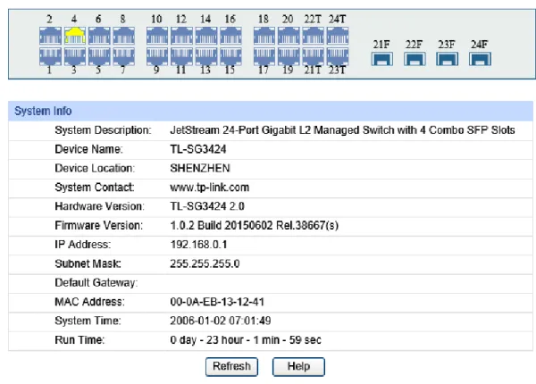
On this page you can view the port connection status and the system information.
The port status diagram shows the working status of 24 10/100/1000Mbps RJ45 ports and 4 SFP ports of the switch. Ports 1-20 and ports 21T-24T are 10/100/1000Mbps ports and ports 21T-24T are Combo ports with SFP ports labeled as 21F-24F.
Choose the menu System →System Info →System Summary to load the following page.
Figure 4-1 System Summary The following entries are displayed on this screen:
Indicates the SFP port is not connected to a device. Indicates the SFP port is at the speed of 1000Mbps. Indicates the SFP port is at the speed of 100Mbps.
When the cursor moves on the port, the detailed information of the port will be displayed.
Figure 4-2 Port Information
Port Info
Port: Displays the port number of the switch.
Type: Displays the type of the port.
Speed: Displays the maximum transmission rate of the port.
Status: Displays the connection status of the port.
Click a port to display the bandwidth utilization on this port. The actual rate divided by theoretical maximum rate is the bandwidth utilization. The following figure displays the bandwidth utilization monitored every four seconds. Monitoring the bandwidth utilization on each port facilitates you to monitor the network traffic and analyze the network abnormities.
Figure 4-3 Bandwidth Utilization
Bandwidth Utilization
Rx: Select Rx to display the bandwidth utilization of receiving packets on this port.
Tx: Select Tx to display the bandwidth utilization of sending packets on this port.
4.1.2 Device Description
On this page you can configure the description of the switch, including device name, device location and system contact.
Choose the menu System →System Info →Device Description to load the following page.
Figure 4-4 Device Description
The following entries are displayed on this screen:
Device Description
Device Name: Enter the name of the switch.
Device Location: Enter the location of the switch.
System Contact: Enter your contact information.
4.1.3 System Time
System Time is the time displayed while the switch is running. On this page you can configure the system time and the settings here will be used for other time-based functions likeACL.
You can manually set the system time, get time from NTP server automatically if it has connected to an NTP server or synchronize with PC’s clock as the system time.
The following entries are displayed on this screen:
Time Info
Current System
Date: Displays the current date and time of the switch. Current Time
Source: Displays the current time Source of the switch.
Time Config
Manual: When this option is selected, you can set the date and time manually.
Get time from NTP
Server: When this option is selected, you can configure the time zone and the IP Address for the NTP server. The switch will get time from NTP server automatically if it has connected to an NTP server.
Time Zone: Select your local time.
Primary/Secondary NTP Server: Enter the IP Address for the
NTP server.
Update Rate: Specify the rate fetching time from NTP server.
Synchronize with
PC’S Clock: When this option is selected, the administrator PC’s clock is utilized.
Note:
1. The system time will be restored to the default when the switch is restarted and you need to reconfigure the system time of the switch.
2. When Get time from NTP Server is selected and no time server is configured, the switch will get time from the time server of the Internet if it has connected to the Internet.
4.1.4 Daylight Saving Time
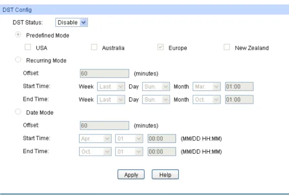
Choose the menu System →System Info →Daylight Saving Time to load the following page.
Figure 4-6 Daylight Saving Time The following entries are displayed on this screen:
DST Config
DST Status: Enable or disable the DST.
Predefined Mode: Select a predefined DST configuration:
USA: Second Sunday in March, 02:00 ~ First Sunday in
November, 02:00.
Australia: First Sunday in October, 02:00 ~ First Sunday in
April, 03:00.
Europe: Last Sunday in March, 01:00 ~ Last Sunday in
October, 01:00.
New Zealand: Last Sunday in September, 02:00 ~ First
Sunday in April, 03:00.
Recurring Mode: Specify the DST configuration in recurring mode. This configuration is recurring in use.
Offset: Specify the time adding in minutes when Daylight
Saving Time comes.
Start/End Time: Select starting time and ending time of
Note:
1. When the DST is disabled, the predefined mode, recurring mode and date mode cannot be configured.
2. When the DST is enabled, the default daylight saving time is of Europe in predefined mode.
4.1.5 System IP
Each device in the network possesses a unique IP Address. You can log on to the Web management page to operate the switch using this IP Address. The switch supports three modes to obtain an IP address: Static IP, DHCP and BOOTP. The IP address obtained using a new mode will replace the original IP address. On this page you can configure the system IP of the switch. Choose the menu System →System Info →System IP to load the following page.
Figure 4-7 System IP The following entries are displayed on this screen:
IP Config
MAC Address: Displays MAC Address of the switch.
IP Address Mode: Select the mode to obtain IP Address for the switch.
Static IP: When this option is selected, you should enter IP
Address, Subnet Mask and Default Gateway manually.
DHCP: When this option is selected, the switch will obtain
network parameters from the DHCP Server.
BOOTP: When this option is selected, the switch will obtain
network parameters from the BOOTP Server.
IP Address: Enter the system IP of the switch. The default system IP is 192.168.0.1 and you can change it appropriate to your needs.
Subnet Mask: Enter the subnet mask of the switch.
Default Gateway: Enter the default gateway of the switch.
Note:
1. Changing the IP address to a different IP segment will interrupt the network communication, so please keep the new IP address in the same IP segment with the local network.
3. If the switch gets the IP address from DHCP server, you can see the configuration of the switch in the DHCP server; if DHCP option is selected but no DHCP server exists in the network, a few minutes later, the switch will restore the setting to the default.
4. If DHCP or BOOTP option is selected, the switch will get network parameters dynamically from the Internet, which means that its IP address, subnet mask and default gateway cannot be configured.
5. The default IP address is 192.168.0.1.
4.1.6 System IPv6
IPv6 (Internet Protocol version 6), also called IPng (IP next generation), was developed by the IETF (Internet Engineering Task Force) as the successor to IPv4 (Internet Protocol version 4). Compared with IPv4, IPv6 increases the IP address size from 32 bits to 128 bits; this solves the IPv4 address exhaustion problem.
IPv6 features
IPv6 has the following features:
1. Adequate address space: The source and destination IPv6 addresses are both 128 bits (16 bytes) long. IPv6 can provide 3.4 x 1038 addresses to completely meet the requirements of
hierarchical address division as well as allocation of public and private addresses.
2. Header format simplification: IPv6 cuts down some IPv4 header fields or move them to IPv6 extension headers to reduce the load of basic IPv6 headers, thus making IPv6 packet handling simple and improving the forwarding efficiency. Although the IPv6 address size is four times that of IPv4 addresses, the size of basic IPv6 headers is 40 bytes and is only twice that of IPv4 headers (excluding the Options field).
3. Flexible extension headers: IPv6 cancels the Options field in IPv4 packets but introduces multiple extension headers. In this way, IPv6 enhances the flexibility greatly to provide scalability for IP while improving the handling efficiency. The Options field in IPv4 packets contains 40 bytes at most, while the size of IPv6 extension headers is restricted by that of IPv6 packets.
4. Built-in security: IPv6 uses IPSec as its standard extension header to provide end-to-end security. This feature provides a standard for network security solutions and improves the interoperability between different IPv6 applications.
5. Automatic address configuration: To simplify the host configuration, IPv6 supports stateful and stateless address configuration.
Stateful address configuration means that a host acquires an IPv6 address and related
6. Enhanced neighbor discovery mechanism: The IPv6 neighbor discovery protocol is a group of Internet control message protocol version 6 (ICMPv6) messages that manages the information exchange between neighbor nodes on the same link. The group of ICMPv6 messages takes the place of Address Resolution Protocol (ARP) message, Internet Control Message Protocol version 4 (ICMPv4) router discovery message, and ICMPv4 redirection message to provide a series of other functions.
Introduction to IPv6 address
1. IPv6 address format
An IPv6 address is represented as a series of 16-bit hexadecimals, separated by colons (:). An IPv6 address is divided into eight groups, and the 16 bits of each group are represented by four hexadecimal numbers which are separated by colons, for example, 2001:0d02:0000:0000:0014: 0000:0000:0095. The hexadecimal letters in IPv6 addresses are not case-sensitive.
To simplify the representation of IPv6 addresses, zeros in IPv6 addresses can be handled as follows:
Leading zeros in each group can be removed. For example, the above-mentioned address
can be represented in shorter format as 2001:d02:0:0:14:0:0:95.
Two colons (::) may be used to compress successive hexadecimal fields of zeros at the
beginning, middle, or end of an IPv6 address. For example, the above-mentioned address can be represented in the shortest format as 2001:d02::14:0:0:95.
Note:
Two colons (::) can be used only once in an IPv6 address, usually to represent the longest successive hexadecimal fields of zeros. If two colons are used more than once, the device is unable to determine how many zeros double-colons represent when converting them to zeros to restore a 128-bit IPv6 address.
An IPv6 address consists of two parts: address prefix and interface ID. The address prefix and the interface ID are respectively equivalent to the network ID and the host ID in an IPv4 address.
An IPv6 address prefix is represented in "IPv6 address/prefix length" format, where "IPv6 address" is an IPv6 address in any of the above-mentioned formats and "prefix length" is a decimal number indicating how many leftmost bits from the preceding IPv6 address are used as the address prefix.
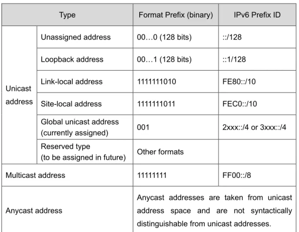
2. IPv6 address classification
IPv6 addresses fall into three types: unicast address, multicast address, and anycast address.
Unicast address: An identifier for a single interface, on a single node. A packet that is sent
Multicast address: An identifier for a set of interfaces (typically belonging to different nodes),
similar to an IPv4 multicast address. A packet sent to a multicast address is delivered to all interfaces identified by that address. There are no broadcast addresses in IPv6. Their function is superseded by multicast addresses.
Anycast address: An identifier for a set of interfaces (typically belonging to different nodes).
A packet sent to an anycast address is delivered to one of the interfaces identified by that address (the nearest one, according to the routing protocols’ measure of distance). The type of an IPv6 address is designated by the first several bits called format prefix. The following table lists the mappings between address types and format prefixes.
Type Format Prefix (binary) IPv6 Prefix ID
Unicast address
Unassigned address 00…0 (128 bits) ::/128 Loopback address 00…1 (128 bits) ::1/128 Link-local address 1111111010 FE80::/10 Site-local address 1111111011 FEC0::/10 Global unicast address
(currently assigned) 001 2xxx::/4 or 3xxx::/4 Reserved type
(to be assigned in future) Other formats
Multicast address 11111111 FF00::/8
Anycast address
Anycast addresses are taken from unicast address space and are not syntactically distinguishable from unicast addresses.
Table 4-1 Mappings between address types and format prefixes 3. IPv6 Unicast Address:
IPv6 unicast address is an identifier for a single interface. It consists of a subnet prefix and an interface ID.
Subnet Prefix: This section is allocated by the IANA (The Internet Assigned Numbers
For all IEEE 802 interface types (for example, Ethernet and FDDI interfaces), Interface IDs in the modified EUI-64 format are constructed in the following way:
The first three octets (24 bits) are taken from the Organizationally Unique Identifier (OUI) of the 48-bit link-layer address (the MAC address) of the interface, the fourth and fifth octets (16 bits) are a fixed hexadecimal value of FFFE, and the last three octets (24 bits) are taken from the last three octets of the MAC address. The construction of the interface ID is completed by setting the universal/local (U/L) bit--the seventh bit of the first octet--to a value of 0 or 1. A value of 0 indicates a locally administered identifier; a value of 1 indicates a globally unique IPv6 interface identifier.
Take MAC address 0012:0B0A:2D51 as an example. Insert FFFE to the middle of the address to get 0012:0BFF:FE0A:2D51. Then set the U/L bit to 1 to obtain an interface ID in EUI-64 format as 0212:0BFF:FE0A:2D51.
IPv6 unicast address can be classified into several types, as shown in Table 4-1. The two most common types are introduced below:
Global unicast address
A Global unicast address is an IPv6 unicast address that is globally unique and is routable on the global Internet.
Global unicast addresses are defined by a global routing prefix, a subnet ID, and an interface ID. The IPv6 global unicast address starts with binary value 001 (2000::/3). The global routing prefix is a value assigned to a site (a cluster of subnets/links) by IANA. The subnet ID is an identifier of a subnet within the site.
The figure below shows the structure of a global unicast address.
Figure 4-8 Global Unicast Address Format
Link-local address
A link-local address is an IPv6 unicast address that can be automatically configured on any interface using the link-local prefix FE80::/10 (1111 1110 10) and the interface identifier in the modified EUI-64 format. Link-local addresses are used in the neighbor discovery protocol and the stateless autoconfiguration process. Nodes on a local link can use link-local addresses to communicate. The figure below shows the structure of a link-local address.
Figure 4-9 Link-local Address Format
IPv6 devices must not forward packets that have link-local source or destination addresses to other links.
Note:
You can configure multiple IPv6 addresses per interface, but only one link-local address.
IPv6 Neighbor Discovery
The IPv6 neighbor discovery process uses ICMP messages and solicited-node multicast addresses to determine the link-layer address of a neighbor on the same network (local link), verify the reachability of a neighbor, and track neighboring devices.
1. IPv6 Neighbor Solicitation Message and Neighbor Advertisement Message
A value of 135 in the Type field of the ICMP packet header identifies a neighbor solicitation (NS) message. Neighbor solicitation messages are sent on the local link when a node wants to determine the link-layer address of another node on the same local link.
After receiving the neighbor solicitation message, the destination node replies by sending a neighbor advertisement (NA) message, which has a value of 136 in the Type field of the ICMP packet header, on the local link. After the source node receives the neighbor advertisement, the source node and destination node can communicate.
Neighbor advertisement messages are also sent when there is a change in the link-layer address of a node on a local link.
Address Resolution
The address resolution procedure is as follows:
Node A multicasts an NS message. The source address of the NS message is the IPv6
address of an interface of node A and the destination address is the solicited-node multicast address of node B. The NS message contains the link-layer address of node A.
Neighbor Reachability Detection
After node A acquires the link-layer address of its neighbor node B, node A can verify whether node B is reachable according to NS and NA messages.
Node A sends an NS message whose destination address is the IPv6 address of node B. If node A receives an NA message from node B, node A considers that node B is reachable.
Otherwise, node B is unreachable.
Duplicate Address Detection
Neighbor solicitation messages are used in the stateless autoconfiguration process to verify the uniqueness of unicast IPv6 addresses before the addresses are assigned to an interface. After node A acquires an IPv6 address, it will perform duplicate address detection (DAD) to determine whether the address is being used by other nodes (similar to the gratuitous ARP function of IPv4). DAD is accomplished through NS and NA messages. The DAD procedure is as follows:
Node A sends an NS message whose source address is the unassigned address :: and
destination address is the corresponding solicited-node multicast address of the IPv6 address to be detected. The NS message contains the IPv6 address.
If node B uses this IPv6 address, node B returns an NA message. The NA message
contains the IPv6 address of node B.
Node A learns that the IPv6 address is being used by node B after receiving the NA
message from node B. Otherwise, node B is not using the IPv6 address and node A can use it.
2. IPv6 Router Advertisement Message
Router advertisement (RA) messages, which have a value of 134 in the Type field of the ICMP packet header, are periodically sent out each configured interface of an IPv6 router.
RA messages typically include the following information:
One or more onlink IPv6 prefixes that nodes on the local link can use to automatically
configure their IPv6 addresses.
Lifetime information for each prefix included in the advertisement.
Sets of flags that indicate the type of autoconfiguration (stateless or stateful) that can be
completed.
Default router information (whether the device sending the advertisement should be used
as a default router and, if so, the amount of time, in seconds, the device should be used as a default router).
Additional information for hosts, such as the hop limit and maximum transmission unit (MTU)
RAs are also sent in response to device solicitation messages. Device solicitation messages, which have a value of 133 in the Type field of the ICMP packet header, are sent by hosts at system startup or anytime needed so that the host can immediately autoconfigure without needing to wait for the next scheduled RA message.
Hosts discover and select default devices by listening to Router Advertisements (RAs).
Stateless address autoconfiguration means that the node automatically configures an IPv6 address and other information for its interface according to the address prefix and other configuration parameters in the received RA messages.
3. IPv6 Neighbor Redirect Message
A value of 137 in the type field of the ICMP packet header identifies an IPv6 neighbor redirect message. Devices send neighbor redirect messages to inform hosts of better first-hop nodes on the path to a destination.
A device will send an IPv6 ICMP redirect message when the following conditions are satisfied:
The receiving interface is the forwarding interface.
The selected route itself is not created or modified by an IPv6 ICMP redirect message. The selected route is not the default route.
You can configure the system’s administrative IPv6 address on this page.
Choose the menu System →System Info →System IPv6 to load the following page.
Figure 4-10 System IPv6 The following entries are displayed on this screen:
Global Config
IPv6: Enable/Disable IPv6 function globally on the switch.
Link-local Address Config
Config Mode: Select the link-local address configuration mode.
Manual: When this option is selected, you should assign a
link-local address manually.
Auto: When this option is selected, the switch will generate a
link-local address automatically.
Status: Displays the status of the link-local address.
Normal: Indicates that the link-local address is normal.
Try: Indicates that the link-local address may be newly
configured.
Repeat: Indicates that the link-local address is duplicate. It is
illegal to access the switch using the IPv6 address(including link-local and global address).
Global Address Autoconfig via RA Message
Enable global address auto
configuration via RA message:
When this option is enabled, the switch automatically configures a global address and other information according to the address prefix and other configuration parameters from the received RA(Router Advertisement) message.
Global Address Autoconfig via DHCPv6 Server
Enable Global Address Autoconfig via DHCPv6 Server:
When this option is enabled, the system will try to obtain the global address from the DHCPv6 Server.
Add a global address manually
Address Format: You can select the global address format according to your requirements.
EUI-64: Indicates that you only need to specify an address
prefix, and then the system will create a global address automatically.
Not EUI-64: Indicates that you have to specify an intact global
address.
Global Address: When selecting the mode of EUI-64, please input the address prefix here, otherwise, please input an intact IPv6 address here.
Global address Table
Select: Select the desired entry to delete or modify the corresponding global address.
Global Address: Modify the global address.
Prefix Length: Modify the prefix length of the global address.
Type: Displays the configuration mode of the global address.
Manual: Indicates that the corresponding address is
configured manually.
Status: Displays the status of the global address.
Normal: Indicates that the global address is normal.
Try: Indicates that the global address may be newly
configured.
Repeat: Indicates that the corresponding address is duplicate.
It is illegal to access the switch using this address.
Tips:
After adding a global IPv6 address to your switch manually here, you can configure your PC’s global IPv6 address in the same subnet with the switch and login to the switch via its global IPv6 address.
4.2 User Management
User Management functions to configure the user name and password for users to log on to the Web management page with a certain access level so as to protect the settings of the switch from being randomly changed.
The User Management function can be implemented on User Table and User Config pages.
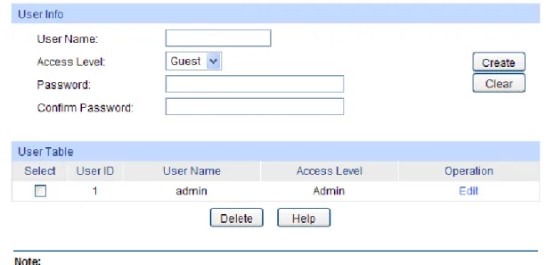
4.2.1 User Table
On this page you can view the information about the current users of the switch.
Choose the menu System →User Management →User Table to load the following page.
Figure 4-11 User Table
4.2.2 User Config
On this page you can configure the access level of the user to log on to the Web management page. The switch provides two access levels: Guest and Admin. The guest only can view the settings without the right to configure the switch; the admin can configure all the functions of the switch. The Web management pages contained in this guide are subject to the admin’s login without any explanation.
Choose the menu System →User Management →User Config to load the following page.
Figure 4-12 User Config The following entries are displayed on this screen:
User Info
User Name: Create a name for users’ login.
Access Level: Select the access level to login.
Admin: Admin can edit, modify and view all the settings of
different functions.
Guest: Guest only can view the settings without the right to edit
and modify.
Password: Type a password for users’ login.
Confirm Password: Retype the password.
User Table
Select: Select the desired entry to delete the corresponding user information. It is multi-optional The current user information cannot be deleted.
User ID, Name,
Access Level: Displays the current user ID, user name, access level and user status.
Operation: Click the Edit button of the desired entry, and you can edit the corresponding user information. After modifying the settings,
4.3 System Tools
The System Tools function, allowing you to manage the configuration file of the switch, can be implemented on Config Restore, Config Backup, Firmware Upgrade, System Reboot and
System Reset pages.
4.3.1 Config Restore
On this page you can upload a backup configuration file to restore your switch to this previous configuration.
Choose the menu System →System Tools →Config Restore to load the following page.
Figure 4-13 Config Restore
The following entries are displayed on this screen:
Config Restore
Restore Config: Click the Restore Config button to restore the backup configuration file. It will take effect after the switch automatically reboots.
Note:
1. It will take a few minutes to restore the configuration. Please wait without any operation. 2. To avoid any damage, please do not power down the switch while it’s being restored.
3. After being restored, the current settings of the switch will be lost. Wrong uploaded configuration file may cause the switch unmanaged.
4.3.2 Config Backup
On this page you can download the current configuration and save it as a file to your computer for your future configuration restore.
Choose the menu System →System Tools →Config Backup to load the following page.
Figure 4-14 Config Backup
The following entries are displayed on this screen:
Config Backup
Backup Config: Click the Backup Config button to save the current configuration as a file to your computer. You are suggested to take this measure before upgrading.
Note:
It will take a few minutes to backup the configuration. Please wait without any operation.
4.3.3 Firmware Upgrade
The switch system can be upgraded via the Web management page. To upgrade the system is to get more functions and better performance. Go to http://www.tp-link.com to download the updated firmware.
Choose the menu System →System Tools →Firmware Upgrade to load the following page.
4.3.4 System Reboot
On this page you can reboot the switch and return to the login page. Please save the current configuration before rebooting to avoid losing the configuration unsaved
Choose the menu System →System Tools →System Reboot to load the following page.
Figure 4-16 System Reboot
Note:
To avoid damage, please do not turn off the device while rebooting.
4.3.5 System Reset
On this page you can reset the switch to the default. All the settings will be cleared after the switch is reset.
Choose the menu System →System Tools →System Reset to load the following page.
Figure 4-17 System Reset
Note:
After the system is reset, the switch will be reset to the default and all the settings will be cleared.
4.4 Access Security
Access Security provides different security measures for the remote login so as to enhance the configuration management security. It can be implemented on Access Control, HTTP Config,
HTTPS Config, SSH Config and Telnet Config pages.
4.4.1 Access Control
On this page you can control the users logging on to the Web management page to enhance the configuration management security. The definitions of Admin and Guest refer to 4.2 User Management.
Choose the menu System →Access Security →Access Control to load the following page.
Figure 4-18 Access Control The following entries are displayed on this screen:
Access Control Config
Control Mode: Select the control mode for users to log on to the Web management page.
IP-based: Select this option to limit the IP-range of the users for
login.
MAC-based: Select this option to limit the MAC Address of the
users for login.
Port-based: Select this option to limit the ports for login.
Access Interface: Select the interface for access control to apply.
IP Address & Mask These fields is available to configure only when IP-based mode is selected. Only the users within the IP-range you set here are allowed for login.
MAC Address: The field is available to configure only when MAC-based mode is selected. Only the user with this MAC Address you set here are allowed for login.
Port: The field is available to configure only when Port-based mode is selected. Only the users connecting to the ports selected are allowed to manage the switch.
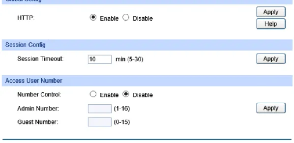
Figure 4-19 HTTP Config The following entries are displayed on this screen:
Global Config
HTTP: Select Enable/Disable the HTTP function on the switch.
Session Config
Session Timeout: If you do nothing with the Web management page within the
timeout time, the system will log out automatically. If you want to reconfigure, please login again.
Access User Number
Number Control: Select Enable/Disable the Number Control function.
Admin Number: Enter the maximum number of the users logging on to the Web
management page as Admin.
Guest Number: Enter the maximum number of the users logging on to the Web
management page as Guest.
4.4.3 HTTPS Config
SSL (Secure Sockets Layer), a security protocol, is to provide a secure connection for the application layer protocol (e.g. HTTP) communication based on TCP. SSL is widely used to secure the data transmission between the Web browser and servers. It is mainly applied through ecommerce and online banking.
SSL mainly provides the following services:
1. Authenticate the users and the servers based on the certificates to ensure the data are transmitted to the correct users and servers;
2. Encrypt the data transmission to prevent the data being intercepted;
3. Maintain the integrality of the data to prevent the data being altered in the transmission.
Adopting asymmetrical encryption technology, SSL uses key pair to encrypt/decrypt information. A key pair refers to a public key (contained in the certificate) and its corresponding private key. By
default the switch has a certificate (self-signed certificate) and a corresponding private key. The Certificate/Key Download function enables the user to replace the default key pair.
After SSL is effective, you can log on to the Web management page via https://192.168.0.1. For the first time you use HTTPS connection to log into the switch with the default certificate, you will be prompted that “The security certificate presented by this website was not issued by a trusted certificate authority” or “Certificate Errors”. Please add this certificate to trusted certificates or continue to this website.
The switch also supports HTTPS connection for IPv6. After configuring an IPv6 address (for example, 3001::1) for the switch, you can log on to the switch’s Web management page via https://[3001::1].
On this page you can configure the HTTPS function.
The following entries are displayed on this screen:
Global Config
HTTPS: Enable or Disable the HTTPS function on the switch. By
default, it’s enabled.
SSL Version 3: Enable or Disable the Secure Sockets Layer Version 3.0. By
default, it’s enabled.
TLS Version 1: Enable or Disable the Transport Layer Security Version 1.0.
By default, it’s enabled.
CIPHERSUITE
RSA_WITH_RC4_128_MD5: Key exchange with RC4 128-bit encryption and MD5 for
message digest. By default, it’s enabled.
RSA_WITH_RC4_128_SHA: Key exchange with RC4 128-bit encryption and SHA for
message digest. By default, it’s enabled.
RSA_WITH_DES_CBC_SHA: Key exchange with DES-CBC for message encryption and
SHA for message digest. By default, it’s enabled.
RSA_WITH_3DES_EDE_CBC
_SHA: Key exchange with 3DES and DES-EDE3-CBC for message encryption and SHA for message digest. By default, it’s enabled.
Session Config
Session Timeout: If you do nothing with the Web management page within the
timeout time, the system will log out automatically. If you want to reconfigure, please login again.
Access User Number
Number Control: Enable or Disable the Number Control function.
Admin Number: Enter the maximum number of the users logging on to the
Web management page as Admin.
Guest Number: Enter the maximum number of the users logging on to the
Web management page as Guest.
Certificate Download
Certificate File: Select the desired certificate to download to the switch. The certificate must be BASE64 encoded.
Key Download
Key File: Select the desired Key to download to the switch. The key must be BASE64 encoded.
Note:
1. The SSL certificate and key downloaded must match each other; otherwise the HTTPS connection will not work.
2. To establish a secured connection using https, please enter https:// into the URL field of the browser.
3. It may take more time for https connection than that for http connection, because https connection involves authentication, encryption and decryption etc.
4.4.4 SSH Config
As stipulated by IETF (Internet Engineering Task Force), SSH (Secure Shell) is a security protocol established on application and transport layers. SSH-encrypted-connection is similar to a telnet connection, but essentially the old telnet remote management method is not safe, because the password and data transmitted with plain-text can be easily intercepted. SSH can provide information security and powerful authentication when you log on to the switch remotely through an insecure network environment. It can encrypt all the transmission data and prevent the information in a remote management being leaked.
Comprising server and client, SSH has two versions, V1 and V2 which are not compatible with each other. In the communication, SSH server and client can auto-negotiate the SSH version and the encryption algorithm. After getting a successful negotiation, the client sends authentication request to the server for login, and then the two can communicate with each other after successful authentication. This switch supports SSH server and you can log on to the switch via SSH connection using SSH client software.
SSH key can be downloaded into the switch. If the key is successfully downloaded, the certificate authentication will be preferred for SSH access to the switch.
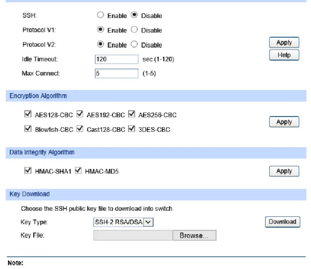
Figure 4-21 SSH Config The following entries are displayed on this screen:
Global Config
SSH: Enable or Disable the SSH function. By default, it’s disabled.
Protocol V1: Enable or Disable the SSH V1 to be the supported protocol.
Protocol V2: Enable or Disable the SSH V2 to be the supported protocol.
Idle Timeout: Specify the idle timeout time. The system will automatically release the connection when the time is up. The default time is 120 seconds.
Max Connect: Specify the maximum number of the connections to the SSH server. No new connection will be established when the number of the connections reaches the maximum number you set. The default value is 5.
Encryption Algorithm
Check the box to enable the corresponding encryption algorithm.
Key Download
Key Type: Select the type of SSH Key to download. The switch supports two types: SSH-2 RSA/DSA and SSH-1 RSA.
Key File: Please ensure the key length of the downloaded file is in the range of 512 to 3072 bits.
Download: Click the Download button to download the desired key file to the switch.
Note:
It will take a long time to download the key file. Please wait without any operation.
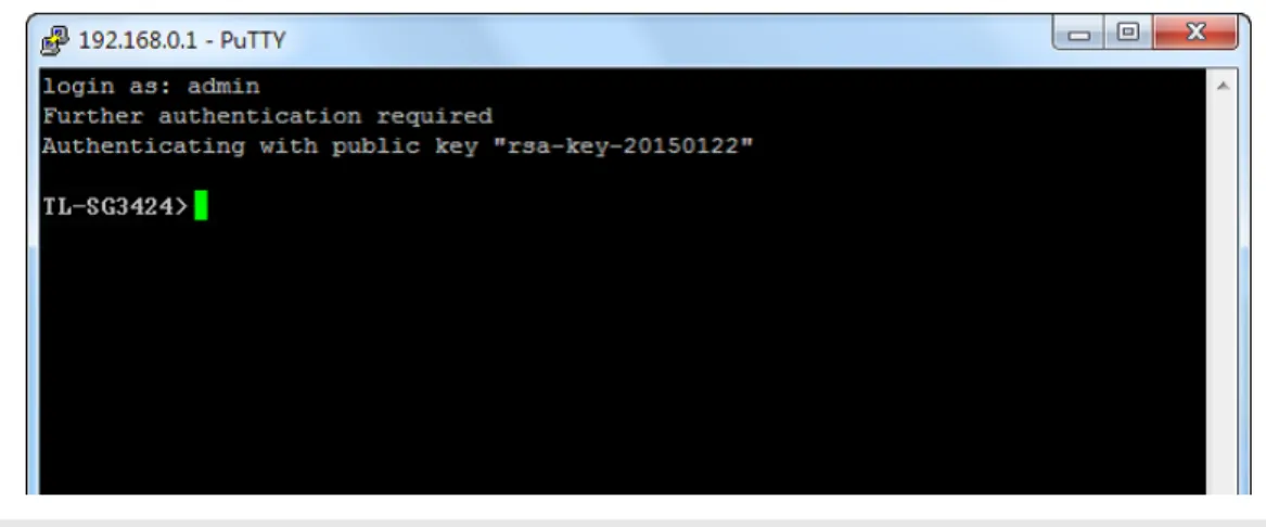
Application Example 1 for SSH:
Network Requirements
1. Log on to the switch via password authentication using SSH and the SSH function is enabled on the switch.
2. PuTTY client software is recommended.
Configuration Procedure
1. Open the software to log on to the interface of PuTTY. Enter the IP address of the switch into
Host Name field; keep the default value 22 in the Port field; select SSH as the Connection type.
2. Click the Open button in the above figure to log on to the switch. Enter the login user name and password, and then you can continue to configure the switch.
Application Example 2 for SSH:
Network Requirements
1. Log on to the switch via password authentication using SSH and the SSH function is enabled on the switch.
2. PuTTY client software is recommended.
Configuration Procedure
1. Select the key type and key length, and generate SSH key.
Note:
1. The key length is in the range of 512 to 3072 bits.
2. During the key generation, randomly moving the mouse quickly can accelerate the key generation.
2. After the key is successfully generated, please save the public key and private key to the computer.
3. On the Web management page of the switch, download the public key file saved in the computer to the switch.
Note:
1. The key type should accord with the type of the key file. 2. The SSH key downloading cannot be interrupted.
4. After the public key is downloaded, please log on to the interface of PuTTY and enter the IP address for login.
After successful authentication, please enter the login user name. If you log on to the switch without entering password, it indicates that the key has been successfully downloaded.
Note:
Following the steps above, you have already entered the User EXEC Mode of the switch. However, to configure the switch, you need a password to enter the Privileged EXEC Mode first. For a switch with factory settings, the Privileged EXEC Mode password can only be configured through the console connection. For how to configure the Privileged EXEC Mode password, please refer to the
1.1.2 Configuring the Privileged EXEC Mode Password in CLI Reference Guide.
4.4.5 Telnet Config
On this page you can Enable/Disable Telnet function globally on the switch.
Choose the menu System→Access Security→Telnet Config to load the following page.
Figure 4-22 Telnet Config The following entries are displayed on this screen:
Global Config
Telnet: Enable or Disable the Telnet function globally on the switch.
Chapter 5 Switching
Switching module is used to configure the basic functions of the switch, including four submenus:
Port, LAG, Traffic Monitor and MAC Address.
5.1 Port
The Port function, allowing you to configure the basic features for the port, is implemented on the
Port Config, Port Mirror, Port Security, Port Isolation and Loopback Detection pages.
5.1.1 Port Config
On this page, you can configure the basic parameters for the ports. When the port is disabled, the packets on the port will be discarded. Disabling the port which is vacant for a long time can reduce the power consumption effectively. And you can enable the port when it is in need.
The parameters will affect the working mode of the port, please set the parameters appropriate to your needs.
Choose the menu Switching → Port → Port Config to load the following page.
Figure 5-1 Port Config Here you can view and configure the port parameters.
Port Config
Port Select: Click the Select button to quick-select the corresponding port based on the port number you entered.