International Journal of Science Engineering and Advance Technology,
IJSEAT, Vol. 4, Issue 7
ISSN 2321-6905
July -2016
www.ijseat.com
Page 305
Modeling and Design of Control Reduced-Rating of DVR With a
Battery Energy Storage System
1
T.Siva Sankar Subramanyam,
2Laxman Dasari
1M-tech Student Scholar,
2Assistant Professor
Department of Electrical &Electronics Engineering,
Prasiddha College Of Engineering&Technology (Pcet)
East Godavari (Dist.); A.P, India
[email protected],
[email protected]Abstract:-In the midst of the past presences a while, In this suspect, assorted voltage implantation anticipates dynamic voltage restorers (DVRs) are investigated with particular spotlight on another technique used to minimize the rating of the voltage source converter (VSC) used as a piece of DVR. Another control technique is proposed to control the capacitor-upheld DVR. The control of a DVR is appeared with a reduced rating VSC. The reference load voltage is assessed using the unit vectors. The synchronous reference frame hypothesis is utilized for the change of voltages from pivoting vectors to the stationary edge. The compensation of the voltage sags, swell, and harmonics is exhibited utilizing a decreased rating. The purposes behind minimize the rating of the voltage source converter (VSC) utilized as a part of DVR permit the compensation of current consonant fixings, consolidating unequal current made in single-stage nonlinear weights. The key pay of the executed with diminished rating of DVR and took after control arrangement for pay conditions is presentations for the way of power through test results by MATLAB/SIMULINK.
Key words: Dynamic voltage restorer (DVR), power quality, unit vector, voltage harmonics, voltage sag, voltage swells.
I. Introduction
POWER QUALITY issues in the present-day dissemination frameworks are tended to in the literature [1]–[6] because of the expanded utilization of delicate and critical equipments, for example, correspondence system, process commercial enterprises, and exact assembling forms. Power quality issues, for example, transients, sags, swells, and different bends to the sinusoidal waveform of the supply voltage influence the execution of these
hardware pieces. Advances, for example, custom power devices are developed to give security against power quality issues. Custom power devices are for the most part of three classifications, for example, arrangement associated compensators known as dynamic voltage restorers (DVRs), shunt-associated compensators, for example, circulation static compensators, and a mix of arrangement and shunt-associated compensators known as unified force quality conditioner [2]–[6]. The DVR can manage the heap voltage from the issues, for example, sag, swell, and harmonics in the supply voltages. Subsequently, it can shield the basic buyer loads from stumbling and ensuing misfortunes [2]. The custom force gadgets are produced and introduced at purchaser point to meet the force quality models.
International Journal of Science Engineering and Advance Technology,
IJSEAT, Vol. 4, Issue 7
ISSN 2321-6905
July -2016
www.ijseat.com
Page 306
DVRs can dispense with the greater part of the sags and minimize the danger of burden stumbling for profound droops, however their primary downsides are their standby misfortunes, the gear cost, furthermore the security plan required for downstream shortcircuits. Numerous arrangements and their issues utilizing DVRs are accounted for, for example, the voltages in a three-stage framework are adjusted [8] and a vitality advanced control of DVR is talked about in [10]. Modern case of DVRs are given in [11], and distinctive control techniques are investigated for various sorts of voltage hangs in [12]–[18]. A correlation of various topologies and control techniques is introduced for a DVR in [19]. The configuration of a capacitor-upheld DVR that secures hang, swell, bending, or unbalance in the supply voltages is examined in [17]. The execution of a DVR with the high-recurrence join transformer is talked about in [24]. In this paper, the control and execution of a DVR are exhibited with a diminished rating voltage source converter (VSC). The synchronous reference Frame (SRF) hypothesis is utilized for the control of the DVR.
II. OPERATION OF DVR
The schematic of a DVR-connected system is
shown in Fig.1
Fig.1 Basic circuit of DVR
The voltage Vinj is embedded such that the heap
voltage Vload is steady in extent and is undistorted,
in spite of the fact that the supply voltage Vs is not
consistent in size or is misshaped.
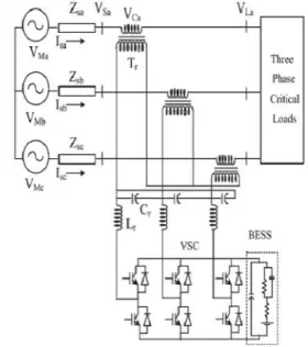
Fig. 2 shows a schematic of a three-phase DVR
connected to restore the voltage of a three-phase
critical load. A three-phase supply is connected to a
critical and sensitive load through a three-phase
series injection transformer.
Fig.2. Schematic of the DVR-connected system
The comparable voltage of the supply of stage VMa
is associated with the purpose of basic coupling
(PCC) VSa through short out impedance Zsa. The
voltage infused by the DVR in stage VCa is such that
the heap voltage VLa is of evaluated size and
undistorted. A three-stage DVR is associated with the
line to infuse a voltage in arrangement utilizing three
single-stage transformers Tr. Lr and Cr speak to the
filter parts used to filter the swells in the infused
voltage. A three-leg VSC with protected door bipolar
transistors (IGBTs) is utilized as a DVR, and a BESS
is associated with its dc transport.
III. CONTROL OF DVR
The sectional diagram of current control scheme is shown in Fig.3
International Journal of Science Engineering and Advance Technology,
IJSEAT, Vol. 4, Issue 7
ISSN 2321-6905
July -2016
www.ijseat.com
Page 306
DVRs can dispense with the greater part of the sags and minimize the danger of burden stumbling for profound droops, however their primary downsides are their standby misfortunes, the gear cost, furthermore the security plan required for downstream shortcircuits. Numerous arrangements and their issues utilizing DVRs are accounted for, for example, the voltages in a three-stage framework are adjusted [8] and a vitality advanced control of DVR is talked about in [10]. Modern case of DVRs are given in [11], and distinctive control techniques are investigated for various sorts of voltage hangs in [12]–[18]. A correlation of various topologies and control techniques is introduced for a DVR in [19]. The configuration of a capacitor-upheld DVR that secures hang, swell, bending, or unbalance in the supply voltages is examined in [17]. The execution of a DVR with the high-recurrence join transformer is talked about in [24]. In this paper, the control and execution of a DVR are exhibited with a diminished rating voltage source converter (VSC). The synchronous reference Frame (SRF) hypothesis is utilized for the control of the DVR.
II. OPERATION OF DVR
The schematic of a DVR-connected system is
shown in Fig.1
Fig.1 Basic circuit of DVR
The voltage Vinj is embedded such that the heap
voltage Vload is steady in extent and is undistorted,
in spite of the fact that the supply voltage Vs is not
consistent in size or is misshaped.
Fig. 2 shows a schematic of a three-phase DVR
connected to restore the voltage of a three-phase
critical load. A three-phase supply is connected to a
critical and sensitive load through a three-phase
series injection transformer.
Fig.2. Schematic of the DVR-connected system
The comparable voltage of the supply of stage VMa
is associated with the purpose of basic coupling
(PCC) VSa through short out impedance Zsa. The
voltage infused by the DVR in stage VCa is such that
the heap voltage VLa is of evaluated size and
undistorted. A three-stage DVR is associated with the
line to infuse a voltage in arrangement utilizing three
single-stage transformers Tr. Lr and Cr speak to the
filter parts used to filter the swells in the infused
voltage. A three-leg VSC with protected door bipolar
transistors (IGBTs) is utilized as a DVR, and a BESS
is associated with its dc transport.
III. CONTROL OF DVR
International Journal of Science Engineering and Advance Technology,
IJSEAT, Vol. 4, Issue 7
ISSN 2321-6905
July -2016
www.ijseat.com
Page 307
Fig.3 Control Block of the DVR that uses the SRF
Method of Control.
The present control proposition is fundamentally required to current references, that are utilized to repays the undesirable burden parts. In this area the source voltage, load current and the dc-voltage converter are measured, while the common streams are produced precisely from the present reference generator. Fig. 3 demonstrates a control piece of the DVR in which the SRF hypothesis is utilized for reference signal estimation. The voltages at the PCC Versus and at the heap terminalVLa detested for determining the IGBTs' door signals. The reference load voltage V∗L is separated utilizing the inferred unit vector [23]. Load voltages (VLa,VLb,VLc) are changed over to the pivoting reference outline utilizing abc−dqochange utilizing Park's change with unit vectors(sin,θ,cos,θ) determined utilizing a stage bolted circle as
=23
⎣ ⎢ ⎢ ⎢ ⎢
⎡cos cos −23 cos +23
sin sin −23 sin +23 1
2
1 2
1 2 ⎦⎥
⎥ ⎥ ⎥ ⎤
(1)
Thus, reference load voltages (V∗La,V∗Lb,V∗Lc)and voltages at the PCCVsare additionally changed over to the pivoting reference outline. At that point, the DVR voltages are acquired in the turning reference outline as
= − (2)
= − (3)
The reference DVR voltages are obtained in the
rotating reference frame
∗ = ∗ − (4)
∗ = ∗ − (5)
The error between the reference and actual DVR
voltages in the rotating reference frame is regulated
using two logic controllers. Reference DVR voltages
in the abc frame are obtained from a reverse Park’s
transformation taking ∗Dd from (4),V∗Dq from
(5),V∗D0as zero as
∗ ∗ ∗ =
cos sin 1
cos − sin − 1
cos + sin − 1
∗ ∗ ∗
(6)
Reference DVR voltages (v∗dvra,v∗dvrb ,v∗dvrc )
and actual DVR voltages(vdvra,vdvrb,vdvrc) are
used in a are used in a pulse width modulated (PWM)
controller to generate gating pulses to a VSC of the
DVR.
Voltages at the PCC vS are converted to the
rotating reference frame using abc−dqo conversion
using Park’s transformation. The harmonics and the
oscillatory components of the voltage are eliminated
using low pass filters (LPFs). The components of
voltages in the d- and q-axes are
International Journal of Science Engineering and Advance Technology,
IJSEAT, Vol. 4, Issue 7
ISSN 2321-6905
July -2016
www.ijseat.com
Page 307
Fig.3 Control Block of the DVR that uses the SRF
Method of Control.
The present control proposition is fundamentally required to current references, that are utilized to repays the undesirable burden parts. In this area the source voltage, load current and the dc-voltage converter are measured, while the common streams are produced precisely from the present reference generator. Fig. 3 demonstrates a control piece of the DVR in which the SRF hypothesis is utilized for reference signal estimation. The voltages at the PCC Versus and at the heap terminalVLa detested for determining the IGBTs' door signals. The reference load voltage V∗L is separated utilizing the inferred unit vector [23]. Load voltages (VLa,VLb,VLc) are changed over to the pivoting reference outline utilizing abc−dqochange utilizing Park's change with unit vectors(sin,θ,cos,θ) determined utilizing a stage bolted circle as
=23
⎣ ⎢ ⎢ ⎢ ⎢
⎡cos cos −23 cos +23
sin sin −23 sin +23 1
2
1 2
1 2 ⎦⎥
⎥ ⎥ ⎥ ⎤
(1)
Thus, reference load voltages (V∗La,V∗Lb,V∗Lc)and voltages at the PCCVsare additionally changed over to the pivoting reference outline. At that point, the DVR voltages are acquired in the turning reference outline as
= − (2)
= − (3)
The reference DVR voltages are obtained in the
rotating reference frame
∗ = ∗ − (4)
∗ = ∗ − (5)
The error between the reference and actual DVR
voltages in the rotating reference frame is regulated
using two logic controllers. Reference DVR voltages
in the abc frame are obtained from a reverse Park’s
transformation taking ∗Dd from (4),V∗Dq from
(5),V∗D0as zero as
∗ ∗ ∗ =
cos sin 1
cos − sin − 1
cos + sin − 1
∗ ∗ ∗
(6)
Reference DVR voltages (v∗dvra,v∗dvrb ,v∗dvrc )
and actual DVR voltages(vdvra,vdvrb,vdvrc) are
used in a are used in a pulse width modulated (PWM)
controller to generate gating pulses to a VSC of the
DVR.
Voltages at the PCC vS are converted to the
rotating reference frame using abc−dqo conversion
using Park’s transformation. The harmonics and the
oscillatory components of the voltage are eliminated
using low pass filters (LPFs). The components of
International Journal of Science Engineering and Advance Technology,
IJSEAT, Vol. 4, Issue 7
ISSN 2321-6905
July -2016
www.ijseat.com
Page 308
= + (7)
= + (8)
The remunerating methodology for pay of voltage
quality issues considers that the heap terminal voltage
ought to be of appraised size and undistorted. With a
specific end goal to keep up the dc transport voltage
of the self-upheld capacitor, a Fuzzy controller is
utilized at the dc transport voltage of the DVR And
the yield is considered as a voltage Vcap for meeting
its misfortunes
( )= ( )+ ( )− ( )+ ( )) (9)
Where vde(n) =v dc−vdc(n) is the error between the
reference v∗dc and sensed dc voltages vdc at then the
sampling instant.The referenced-axis load voltage is
therefore expressed as follows:
∗= − (10)
The amplitude of load terminal voltage VL is
controlled to its reference voltage V ∗ L using
another logic controller. The output of the controller
is considered as the reactive component of voltage
vqr for voltage regulation of the load terminal
voltage. The amplitude of load voltage VL at the
PCC is calculated from the ac voltages
(VLa,VLb,VLc) as
= (2/3) / ( + + ) (11)
Where vte(n) =V ∗ L−VL(n) denotes the error
between the reference V∗L and actual VL(n) load
terminal voltage amplitudes at then the sampling
instant. The reference load quadrature axis voltage is
expressed as follows:
∗= + (12)
Reference load voltages (v∗La ,v∗Lb ,v∗Lc ) in the
abc frame are obtained from a reverse Park’s
transformation as in (7). The error between sensed
load voltages (VLa,VLb,VLc)and reference load
voltages is used over a controller to generate gating
pulse to the VSC of the DVR.
IV. MODELING AND SIMULATION
The DVR-connected system consisting
of a three-phase supply, three-phase critical loads,
and the series injection transformers shown in Fig. 2
is modeled in MATLAB/Simulink environment along
with a simpower system toolbox and is shown in
International Journal of Science Engineering and Advance Technology,
IJSEAT, Vol. 4, Issue 7
ISSN 2321-6905
July -2016
International Journal of Science Engineering and Advance Technology,
IJSEAT, Vol. 4, Issue 7
ISSN 2321-6905
July -2016
www.ijseat.com
Page 310
Fig.4Matlab based model of the BEES- supported DVR connected system.
International Journal of Science Engineering and Advance Technology,
IJSEAT, Vol. 4, Issue 7
ISSN 2321-6905
July -2016
www.ijseat.com
Page 311
Fig5. Dynamic performance of DVR with in phase injection during voltage sag and swell applied to critical load.
V PERFORMANCE OF DVR
The execution of the DVR is exhibited for various supply voltage unsettling influences, for example, voltage hang and swell. Fig.4 demonstrates the transient execution of the framework under voltage list and voltage swell conditions. At 0.2 s, a droop in supply voltage is made for five cycles, and at 0.3 s, a swell in the supply voltages is made for five cycles. It is watched that the heap voltage is directed to steady plentifulness under both droop and swell conditions. PCC voltages Versus, load voltages VL, DVR voltages VC, sufficiency of burden voltage VL and PCC voltage Versus, source streams Is, reference load voltages VL ref, and dc transport voltage Vdc are additionally delineated in Fig3. The heap voltage is kept up sinusoidal by infusing appropriate pay voltage by the DVR. The total harmonic distortions(THDs) of the voltage at the PCC, supply current and burden voltage are appeared in Figs. 6-7, separately.
It is watched that the heap voltage THD is lessened to a level of 0.51% from the sourcevoltage of 6.41%. The sizes of the voltage infused by the DVR for alleviating the same sorts of hang in the supply with various edges of infusion are watched. . The infusion of voltage in quadrature with the line current.
Fig.6. Load voltage and harmonic spectrum during Disturbance
Fig.7. Load current and harmonic spectrum during the disturbance.
International Journal of Science Engineering and Advance Technology,
IJSEAT, Vol. 4, Issue 7
ISSN 2321-6905
July -2016
www.ijseat.com
Page 312
Fig.9.Dynamic performance of the capacitor– supported DVR During a Voltage Swell.
VI CONCLUSION
This paper shows the operation of a DVR has been shown with another control method utilizing different voltage infusion plans. An examination of the execution of the DVR with various plans has been performed with a diminished rating VSC, including a capacitor-upheld DVR. The reference load voltage has been evaluated utilizing the technique for unit vectors, and the control of DVR has been accomplished, which minimizes the blunder of voltage infusion. The SRF hypothesis has been utilized for assessing the reference DVR voltages. It is inferred that the voltage infusion in-stage with the PCC voltage results in least appraising of DVR yet at the expense of a vitality source at its dc transport.
APPENDEX