Wind Energy Conversion Systems using DFIG with Integrated
Active Filter Capabilities
B V D N Pourna Ganga Tejaswi1, G T P Naidu2
M.Tech Student, Department of EEE, PCET, Anathavaram, India.1 Asst. Professor, Department of EEE, PCET, Anathavaram, India.2
Abstract— Doubly Fed Induction Generator for Wind Energy Conversion Systems manages the operation of doubly nourished acceptance generator with an incorporated dynamic channel capacities utilizing network side converter (GSC). The principle commitment of this work lies in the control of GSC for providing sounds notwithstanding its slip control exchange. The rotor-side converter (RSC) is utilized for accomplishing most extreme power extraction and to supply required responsive energy to DFIG. Wind vitality change framework (WECS) functions as a static compensator (STATCOM) for providing music notwithstanding when the wind turbine is in shutdown condition. Control calculations of both GSC and RSC are introduced in detail. Actualized extend DFIG-based WECS is reproduced utilizing MATLAB/Simulink . A model of the proposed DFIG based WECS is produced utilizing a fluffy logic controller. The wind vitality is the favored for all renewable vitality sources. In the underlying days, wind turbines have been utilized as settled speed twist turbines with squirrel confine acceptance generator and capacitor banks. The majority of the wind turbines are settled speed as a result of their straightforwardness and minimal effort.
Index Terms— Doubly fed induction generator (DFIG),integrated active filter, nonlinear load, power quality, wind energy conversion system (WECS),Fuzzy logic controller(FLC).
I. INTRODUCTION
The increase in population and industrialization, the energy demand has increased significantly. The conventional energy sources such as coal, oil, and gas are limited in nature. There is a need for renewable energy sources for the future energy demand. The other main advantages of this renewable source are eco-friendliness and unlimited in nature. Due to technical advancements, the cost of the wind power produced is comparable to that of conventional power plants. Therefore, the wind energy is the most preferred out of all renewable energy sources. In the initial days, wind turbines have been used as fixed speed wind turbines with squirrel cage induction generator and capacitor banks. Most of the wind turbines are fixed speed because of their simplicity and low cost. By observing and implementing wind turbine characteristics, one can clearly identify that for extracting maximum power, the machine should run at varying rotor speeds at different wind speeds. An implemented modern power electronic converter, the machine is able to run at adjustable speeds. These variable speed wind turbines are able to improve the wind energy production. Out of all factor speed wind turbines, doubly encouraged acceptance generators (DFIGs) are favored in light of their ease. The upsides of this DFIG are the higher vitality
yield, bring down converter rating, and better use of generators.
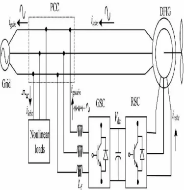
symphonious streams are moderated by GSC control, so that the stator and lattice ebbs and flows are without consonant. RSC is controlled for accomplishing most extreme power point following (MPPT) furthermore to make solidarity control figure at the stator side utilizing voltage-arranged reference outline. Synchronous reference outline (SRF) control technique is utilized for separating the basic segment of load streams for the GSC control.
Fig 1. Proposed system configuration.
III. DESIGN OFDFIG-BASEDWECS
Choice of evaluations of VSCs and dc-connect voltage is especially essential for the fruitful operation of WECS. The evaluations of DFIG and dc machine utilized as a part of this test framework are given in Appendix. In this segment, an itemized outline of VSCs also, dc-connect voltage is examined for the trial framework utilized as a part of the research center.
IV. CONTROL STRATEGY
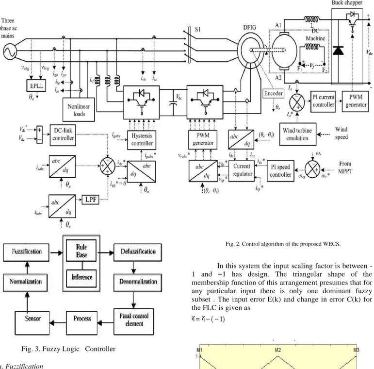
Control calculations for both GSC and RSC are exhibited in this segment. Finish control schematic is given in Fig. 2. The control calculation for copying wind turbine attributes utilizing dc machine and Type A chopper is additionally appeared in Fig. 2.The primary reason for RSC is to concentrate most extreme power with autonomous control of dynamic and responsive forces. Here, the RSC is controlled in voltage-situated reference outline. Accordingly, the dynamic and responsive forces are controlled by controlling direct and quadrature pivot rotor streams (idr and iqr), individually. Coordinate pivot reference rotor current is chosen with the end goal that most extreme power is extricated for a specific wind speed. This can be accomplished by running the DFIG at a rotor speed for a specific wind speed. Along these lines, the external circle is chosen as a speed controller for accomplishing direct pivot reference rotor current.SRF hypothesis created in this paper to repay streams and voltage conditions as immediate and quadrature hub for framework side and rotor side converter.
V. FUZZY LOGIC CONTROL
Fig. 3. Fuzzy Logic Controller
a. Fuzzification
Participation work qualities are doled out to the phonetic factors, utilizing seven fluffy subsets: NB(Negative Big), NM(Negative Medium), NS (Negative Small), ZE (Zero), PS (Positive Small),PM(Positive Medium) and PB (Positive Big). The parcel of fluffy subsets and the state of participation capacity adjust the take care of business to proper framework. Input mistake E(k) and change in blunder CE(k) of qualities which is standardized by an info scaling element as appeared in table 1.
Fig. 2. Control algorithm of the proposed WECS.
In this system the input scaling factor is between -1 and +-1 has design. The triangular shape of the membership function of this arrangement presumes that for any particular input there is only one dominant fuzzy subset . The input error E(k) and change in error C(k) for the FLC is given as
ሻ=ሻ− ( − 1)
. Ouput(c)
Fig. 4.(a)(b)(c) Membership functions
b. Inference Method
Several composition methods such as Min and Max-Dot have been proposed and Min method is used. Minimum operator and Maximum operator of output membership function is of each rule and it is shown in Table 1.
c. Defuzzification
As a plant usually requires a non-fuzzy value of control, a defuzzification stage is needed. To compute the output of the FLC, "height" method is used and the FLC output modifies the control output. Further, the output of FLC controls the switch in the inverter. In order to control these parameters, they are sensed and compared with the reference values. To achieve this, the membership functions of Fuzzy controller are: error, change in error and output as shown in Figs.(3), (4). In the present work, for fuzzification, non uniform fuzzifier has been used. If the exact values of error and change in error are small or large, they are divided
conversely. The α is self-adjustable factor and to regulate operation. E is the error of the system, C is the change in error and u is the control variable. If the system is not in balanced it indicates an error 'E' if the value is large. While the error 'E' value is small it indicates that the system is near to balanced state. If system is unbalanced, the control variables should be enlarge to balance the system as early as possible. For system stability overshoot plays an important role. For restraining oscillations and system stability it requires less overshoot. 'C' plays an important role, while
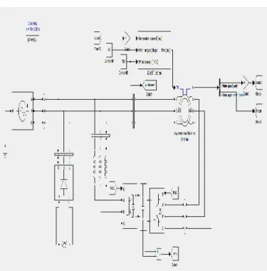
FIG 5.1 Block diagram of proposed DFIG-based WECS at fixed wind speed of 10.6 m/s (rotor speed of 1750 rpm).
Fig. 5.3. Simulated performance of the proposed DFIG-based WECS at fixed wind speed of 10.6 m/s (rotor speed of 1750 rpm).
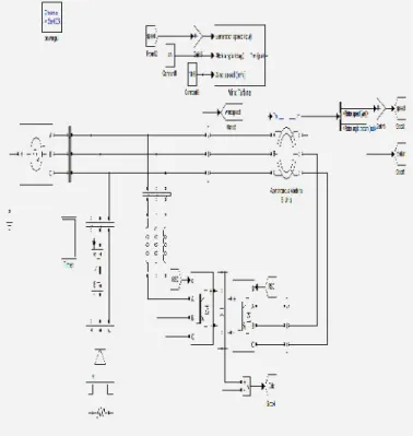
FIG 5.4 MAIN BLOCK DIAGRAM OF proposed DFIG-based WECS working as a STATCOM at zero wind speed.
Fig.5.5 Simulated performance of the proposed DFIG-based WECS working as a STATCOM at zero wind speed.
Fig. 5.7 Dynamic performance of DFIG-based WECS for the sudden removal and application of local loads.
FIG 5.8 Block diagram of proposed DFIG for fall in wind speed
Fig5.9 Simulated performance of proposed DFIG for fall in wind speed.
FIG 5.11 TOTAL HARMONIC DISTORTION OF GRID CURRENT
FIG5.12 TOTAL HARMONIC DISTORTION OF LOAD CURRENT
FIG 5.13 TOTAL HARMONIC DISTORTION OF SOURCE CURRENT
FIG 5.14 TOTAL HARMONIC DISTORTION OF SOURCE VOLTAGE
VI. CONCLUSION
The GSC control algorithm of the proposed DFIG has been modified for supplying the harmonics and reactive power of the local loads. In this proposed DFIG, the reactive power for the induction machine has been supplied from the RSC and the load reactive power has been supplied from the GSC. The decoupled control of both active and reactive powers has been achieved by RSC control. The proposed DFIG has also been verified at wind turbine stalling condition for compensating harmonics and reactive power of local loads. This proposed DFIG-based WECS with an integrated active filter has been simulated using MATLAB/Simulink environment, and the simulated results are verified with test results of the developed prototype of this WECS. Fuzzy controller is replaced by PI controller for the harmonic reduction of GSC and RSC controller. Steady-state performance of the proposed DFIG has been demonstrated for a wind speed. Dynamic performance of this proposed GSC control algorithm has also been verified for the variation in the wind speeds and for local nonlinear load.
REFERENCES
[1] N. K. Swami Naidu, Member, IEEE, and Bhim Singh, Fellow, IEEE” Doubly Fed Induction Generator for Wind Energy Conversion Systems With Integrated ActiveFilter Capabilities” IEEE TRANSACTIONS ON INDUSTRIAL INFORMATICS, VOL. 11, NO. 4, AUGUST 2015
[2] D. M. Tagare, Electric Power Generation the Changing Dimensions. Piscataway, NJ, USA: IEEE Press, 2011.
[3] G. M. Joselin Herbert, S. Iniyan, and D. Amutha, “A review of technical issues on the development of wind farms,”
concepts for windturbines,” IEEE Trans. Energy Convers., vol. 21, no. 3, pp. 725–733, Sep. 2006.
[8] R. Datta and V. T. Ranganathan, “Variable-speed wind power generation using doubly fed wound rotor induction machine—A comparison with alternative schemes,” IEEE Trans. Energy Convers., vol. 17, no. 3, pp. 414–421, Sep. 2002.
[9] E. Muljadi, C. P. Butterfield, B. Parsons, and A Ellis,
“Effect of variable speed wind turbine generator on stability of a weak grid,”IEEE Trans. Energy Convers., vol. 22, no. 1, pp. 29–36, Mar. 2007.
[10] R. Pena, J. C. Clare, and G. M. Asher, “Doubly fed
induction generator using back-to-back PWM converters and its application to variable-speed wind-energy generation,”IEE Proc. Elect. Power Appl., vol. 143, no. 3, pp. 231–241, May 1996.
[11] S. Muller, M. Deicke, and R. W. De Doncker, “Doubly
fed induction generator systems forwind turbines,”IEEE Ind. Appl. Mag., vol. 8, no. 3, pp. 26–33, May/Jun. 2002.
[12] W. Qiao and R. G. Harley, “Grid connection requirements and solutions for DFIG wind turbines,” inProc. IEEE Energy 2030 Conf. (ENERGY’08), Nov. 17–18, 2008, pp. 1–8.
[13] A. Petersson, T. Thiringer, L. Harnefors, and T. Petru,
“Modeling and experimental verification of grid interaction of a DFIG wind turbine,”IEEE Trans. Energy Convers., vol. 20, no. 4, pp. 878–886, Dec. 2005.
[14] H. M. Hasanien, “A set-membership affine projection algorithm-based adaptive-controlled SMES units for wind
farms output power smoothing,”IEEE Trans. Sustain. Energy, vol. 5, no. 4, pp. 1226–1233, Oct. 2014.
[15] Z. Saad-Saoud, M. L. Lisboa, J. B. Ekanayake, N.
Jenkins, and G. Strbac, “Application of STATCOMs to wind
farms,”IEE Proc. Gener. Transmiss. Distrib., vol. 145, no. 5, pp. 511–516, Sep. 1998.
[16] G. O. Suvire and P. E. Mercado, “Combined control of a