Design Analysis of Low Speed Flywheels For Automobiles
S.Sivakumar#1, M. Manoj#2, P.Satish Reddy#3, N.Guru Murthy#4#1Scholar of Master of Technology,#2Asst Professor,#3Assoc Professor,#4Asst Professor Dept of Mechanical Engineering, Prasiddha College of Engg & Tech, Anathavaram
#1[email protected],#2[email protected],#3[email protected],#4[email protected]
ABSTRACT
This paper concentrates on investigating the impacts of flywheel geometry on its vitality stockpiling or convey capacity per unit mass, additionally characterized as most extreme particular vitality. In this paper we have investigated different profiles of flywheel and the put away active vitality per unit mass is ascertained for the separate flywheel. Different profiles are outlined and examination in CAE instrument (CATIAV5). investigation is done for various states of the flywheels and von mises stresses and aggregate misshapening are resolved. It demonstrates that shrewd plan of flywheel geometry significantly affect the Specific Energy stockpiling and decrease the operational burdens applied on the pole because of lessened mass at high rotational rates. Proficient flywheel configuration used to boost the latency of minute for least material utilized and assurance high unwavering quality and long life.
The execution characteristics of flywheels, inspecting two sorts of materials–steel and cast press
Keywords— Flywheel, specific energy, stored kinetic energy.
1. INTRODUCTION OF FLYWHEEL
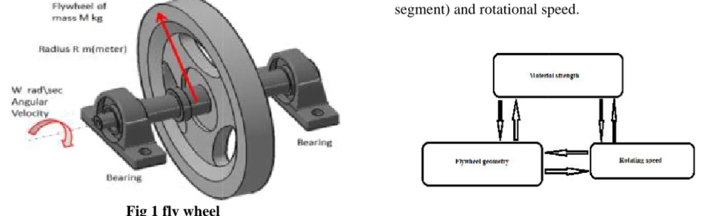
A flywheel is an inertial vitality stockpiling gadget. It assimilates mechanical vitality and fills in as a repository, putting away vitality amid the period when the supply of vitality is more than prerequisite then it discharges amid the period when the necessity of vitality is more than the supply.
Fig 1 fly wheel
1.1 FUNCTION AND NEED OF OPERATION
The primary capacity of a flywheel is to smoothen out varieties in the speed of a pole brought on by torque changes. In the event that the wellspring of the heap torque is fluctuating in nature. Many machines have stack designs that cause the torque time capacity to change over the cycle. For instance inner burning motors with maybe a couple chambers, Piston compressors, punch squeezes, shake crushers and so on are alternate frameworks that have fly wheel.. Flywheel retains mechanical vitality by expanding its precise speed and conveys the put away vitality by diminishing its speed. Flywheel goes about as a repository by putting away vitality amid the period when the supply of vitality is more than the prerequisite and discharging it amid the period when the necessity of the vitality is more than the supply.
Flywheel gives a compelling approach to smooth out the variance of speed. The put away active vitality in view of the mass snapshot of latency and rotational speed. A flywheel is a mechanical gadget with a huge snapshot of latency utilized as a capacity gadget for rotational vitality. Flywheels oppose changes in their rotational speed, which steadies the pivot of the pole. Flywheels have turned into the subject of broad research as power stockpiling gadgets for utilizations in vehicles. Flywheel vitality stockpiling frameworks are thought to be an appealing other option to electrochemical batteries because of higher put away vitality thickness, higher life time, and deterministic condition of charge and naturally clean nature.
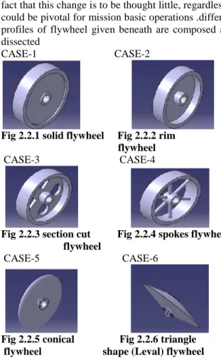
The execution of a flywheel can be ascribed to three variables, i.e., material quality, geometry (cross-segment) and rotational speed.
Fig 1.1 factors affecting flywheel performance
Design Analysis of Low Speed Flywheels For Automobiles
S.Sivakumar#1, M. Manoj#2, P.Satish Reddy#3, N.Guru Murthy#4#1Scholar of Master of Technology,#2Asst Professor,#3Assoc Professor,#4Asst Professor Dept of Mechanical Engineering, Prasiddha College of Engg & Tech, Anathavaram
#1[email protected],#2[email protected],#3[email protected],#4[email protected]
ABSTRACT
This paper concentrates on investigating the impacts of flywheel geometry on its vitality stockpiling or convey capacity per unit mass, additionally characterized as most extreme particular vitality. In this paper we have investigated different profiles of flywheel and the put away active vitality per unit mass is ascertained for the separate flywheel. Different profiles are outlined and examination in CAE instrument (CATIAV5). investigation is done for various states of the flywheels and von mises stresses and aggregate misshapening are resolved. It demonstrates that shrewd plan of flywheel geometry significantly affect the Specific Energy stockpiling and decrease the operational burdens applied on the pole because of lessened mass at high rotational rates. Proficient flywheel configuration used to boost the latency of minute for least material utilized and assurance high unwavering quality and long life.
The execution characteristics of flywheels, inspecting two sorts of materials–steel and cast press
Keywords— Flywheel, specific energy, stored kinetic energy.
1. INTRODUCTION OF FLYWHEEL
A flywheel is an inertial vitality stockpiling gadget. It assimilates mechanical vitality and fills in as a repository, putting away vitality amid the period when the supply of vitality is more than prerequisite then it discharges amid the period when the necessity of vitality is more than the supply.
Fig 1 fly wheel
1.1 FUNCTION AND NEED OF OPERATION
The primary capacity of a flywheel is to smoothen out varieties in the speed of a pole brought on by torque changes. In the event that the wellspring of the heap torque is fluctuating in nature. Many machines have stack designs that cause the torque time capacity to change over the cycle. For instance inner burning motors with maybe a couple chambers, Piston compressors, punch squeezes, shake crushers and so on are alternate frameworks that have fly wheel.. Flywheel retains mechanical vitality by expanding its precise speed and conveys the put away vitality by diminishing its speed. Flywheel goes about as a repository by putting away vitality amid the period when the supply of vitality is more than the prerequisite and discharging it amid the period when the necessity of the vitality is more than the supply.
Flywheel gives a compelling approach to smooth out the variance of speed. The put away active vitality in view of the mass snapshot of latency and rotational speed. A flywheel is a mechanical gadget with a huge snapshot of latency utilized as a capacity gadget for rotational vitality. Flywheels oppose changes in their rotational speed, which steadies the pivot of the pole. Flywheels have turned into the subject of broad research as power stockpiling gadgets for utilizations in vehicles. Flywheel vitality stockpiling frameworks are thought to be an appealing other option to electrochemical batteries because of higher put away vitality thickness, higher life time, and deterministic condition of charge and naturally clean nature.
The execution of a flywheel can be ascribed to three variables, i.e., material quality, geometry (cross-segment) and rotational speed.
1.1.1 Material quality
More grounded materials could embrace extensive working burdens, subsequently could be keep running at high rotational velocities permitting putting away more vitality. Subsequently could be keep running at high rotational rates enable wing to store more vitality.
1.1.2 Rotational speed
It straightforwardly controls the vitality put away, higher velocities wanted for more vitality stockpiling, yet high speeds attest inordinate loads on both flywheel and direction amid the pole outline.
1.1.3 Geometry of flywheel
It controls the Specific Energy and motor vitality stockpiling capacity of the flywheel. Any advancement impact of flywheel cross-area may contribute significant changes in dynamic vitality stockpiling ability subsequently decreasing both general shaft or bearing burdens and material disappointment events. Flywheel productivity incorporates the measure of active vitality put away per unit mass and mechanical misfortunes.
To enhance the nature of the item and so as to have protected and solid plan, it is important to explore the burdens incited in the segment amid working condition.
At the point when the flywheel turns, outward strengths follows up on the flywheel because of which elastic and twisting anxiety are actuated in a flywheel. To counter the necessity of smoothing out the expansive motions in speed amid a cycle of a mechanical framework.
2. GEOMETRICAL DIMENTIONS OF FLYWHEEL
State of the flywheel is influenced on shaft stress and vitality stockpiling for unit mass in flywheel, the distinctive sort's flywheel is outlined and broke down with consistent external and inward widths at speed 750 rpm.
External width of flywheel (do) =380mm,
Internal width of flywheel (di) =50mm.
2.1 DESIGN APPROACH
There are two phases to the plan of a flywheel.
2. At that point flywheel geometry must be characterized that caters the required snapshot of idleness in a sensibly measured bundle and is protected against disappointment at the outlined rates of operation.
A flywheel is composed and dissected. By utilizing advancement method different parameter like material, cost of flywheel can be streamlined and by applying an approach for change of different working parameter like, geometry shape and vitality putting away limit per unit mass, I can discovered greatest vitality stockpiling in flywheels.
2.2 OTHER FLYWHEEL GEOMETRIES
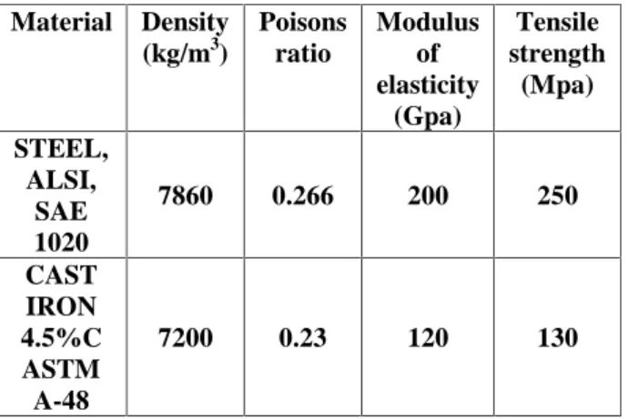
Other flywheel geometries taken under review are strong flywheel, edge flywheel, area cut flywheel, spokes flywheel, funnel shaped flywheel and triangle shape (leval) flywheel. Keeping outside breadth 380 mm, put away active vitality is figured for unit mass for these profiles.
This paper obviously portrays the significance of flywheel geometry plan and material choice and its commitment in the vitality stockpiling. In spite of the fact that this change is to be thought little, regardless it could be pivotal for mission basic operations .different profiles of flywheel given beneath are composed and dissected
CASE-1 CASE-2
Fig 2.2.1 solid flywheel Fig 2.2.2 rim flywheel
CASE-3 CASE-4
Fig 2.2.3 section cut Fig 2.2.4 spokes flywheel flywheel
Flywheels are vitality stockpiling gadgets and consequently while considering their assembling generally the accompanying variables are considered
1. Material cost
2. Material weight
3. Vitality stockpiling for unit mass
4. Material rigidity.
Since vitality put away is corresponding to the elasticity of material and the mass. Remembering the above focuses, steel flywheel for low rpm, and carbon fiber for higher rpm is ordinarily utilized. Flywheels are produced using a wide range of materials; the requests of the application decide the decision of material. Solid metal flywheels are utilized as a part of old steam motors, inward burning motors. Flywheels utilized as a part of autos to smooth power-transmission might be made of solid metal or nodular iron, steel or aluminum relying upon the execution application, Flywheels produced using high-quality steel or composites have been proposed for use in vehicle control stockpiling and stopping mechanisms
Attributes of flywheel materials appeared in Table 3
Table no 3.Materials used for analysis
3.1 GEOMETRY SHAPE FACTOR
The highest possible value for the shape factor of a flywheel rotor, K=1, which can only be
achieved by the theoretical constant-stress
disc geometry A constant-thickness disc geometry has a shape factor of K=0.606, while for a rod of constant thickness the value is K=0.333. A thin cylinder has a shape factor of K=0.5
Table no 3.1 calculated shape factors for used geometries
Shape of geometry
Shape factor for cast iron
Shape factor for steel
Solid disc K=1 K=1
Rim K=0.666 K=0.666
Cut section K=0.666 K=0.666
Spokes K=0.333 K=0.333
Conical K=0.619 K=0.612
Triangle shape(pierced disc)
K=0.499 K=0.516
4. ANALYSIS OF FLYWHEEL 4.1 FEA ANALYSIS
In industry by and large two sorts of examination are utilized: 2-D demonstrating, and3-D displaying. While 2-D demonstrating monitors effortlessness and enables the examination to be keep running on a moderately typical PC, it tends to yield less exact outcomes. 3-D demonstrating, in any case, creates more precise outcomes.
The CATIAV5 CAE (Computer-Aided Engineering) programming project was utilized to plan strong geometry and examination the conduct of mechanical bodies under basic stacking conditions
4.2 STRUCTURAL ANALYSIS
Basic investigation is completed on six unique states of flywheels and I have to lessen material of flywheel and discover more vitality stockpiling for least material and contrasted consequences of cast iron flywheel and aftereffects of steel flywheel at same rotational speed.
4.3 ELEMENT TYPE
The straight tetrahedron components are speedier computationally however less precise. Then again, the explanatory components require more computational assets however prompt more precise outcomes. Another imperative element of explanatory components is that they can fit bended surfaces better. All in all, the examination of massive items requires the utilization of strong components. Hexahedral components are likewise accessible on a restricted premise in late arrivals of CATIA.
Material Density (kg/m3)
Poisons ratio
Modulus of elasticity
(Gpa)
Tensile strength
(Mpa)
STEEL, ALSI,
SAE 1020
7860 0.266 200 250
CAST IRON 4.5%C ASTM A-48
Fig 4.3 Tetrahedron elements
4.4 MESHING METHOD
The idea of component size is simple. A littler component estimate prompts more precise outcomes to the detriment of a bigger calculation time. The "droop" phrasing is one of a kind to CATIA. In FEA, the geometry of a section is approximated with the components. The surface of the part and the FEA estimation of a section don't correspond. The "droop" parameter controls the deviation between the two. In this manner, a littler "hang" esteem could prompt better outcomes. There is a connection between these parameters that one doesn't need to be worried with now. The physical sizes of the agent "size" and "hang" on the screen, which additionally restrain the coarseness of the work, can be changed by the client. There are two approaches to change these parameters: The main strategy is to double tap on the delegate symbols on the screen which constrains the OCTREE Tetrahedron Mesh box and Change the default qualities to coordinate the numbers in the container.
See that the kind of the components utilized (straight/illustrative) is additionally set in this crate. Select OK.
The second technique for achieving this container is through the tree. By double tapping on the branch named OCTREE Tetrahedron Mesh, a similar box opens enabling the client to change the qualities.
With a specific end goal to see the created work, you can indicate the curser the branch Nodes and Elements, right snap and select Mesh Visualization. This progression might be marginally unique in some UNIX machines. After playing out this operation a Warning box shows up which can be disregarded by choosing OK. For the work parameters utilized, the accompanying lattice is shown on the screen.
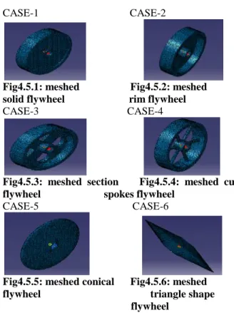
4.5 MESHED FLYWHEEL MODELS
flywheel model of different sorts are appeared in beneath
CASE-1 CASE-2
Fig4.5.1: meshed Fig4.5.2: meshed solid flywheel rim flywheel
CASE-3 CASE-4
Fig4.5.3: meshed section Fig4.5.4: meshed cut flywheel spokes flywheel
CASE-5 CASE-6
Fig4.5.5: meshed conical Fig4.5.6: meshed flywheel triangle shape
flywheel
4.6 STRUCTURAL ANALYSES ON STEEL FLYWHEELS
CASE-1
Fig 4.6.1(a) shows displacement of Solid Fly Wheel, which has the deformed shape of the flywheel analysis. The value of deformation is 0.000338 mm.
Fig 4.6.1(a): solid flywheel displacement
Fig 4.6.1(b) shows solid flywheel, which represents the maximum stress developed in the flywheel The von-mises stress of flywheel is 1.34 E+006 N/m2.
Fig 4.6.2(a): rim flywheel displacement
Fig 4.6.2(b) shows rim flywheel,which represents the maximum stress developed in the flywheel. The von-mises stress of flywheel is 1.98E+06N/m2
Fig 4.6.2(b): von-mises stress of rim flywheel
CASE-3
Fig 4.6.3(a) shows displacement of section cut flywheel, which has the deformed shape of the flywheel analysis the value of deformation is 0.00158 mm
Fig4.6.3 (a): displacement of section cut flywheel
Fig 4.6.3(b) shows section cut flywheel, which represents the maximum stress developed in the flywheel. The von- mises stress of flywheel is 5.07E+006 N/m2
Fig 4.6.3(b): von-mises stress of section cut flywheel
CASE-4
Fig 4.6.4(a) shows displacement of spokes flywheel, which has represents the deformed shape of the flywheel the value of deformation is 0.00138 mm
Fig 4.6.4 (a): displacement of spokes flywheel
4.6.4(b) shows spokes flywheel, which Shows the maximum stress developed in the flywheel analysis. The von-mises stress of flywheel is 3.3E+006 N/m2
Fig 4.6.4(b): von-mises stress of spokes flywheel
CASE-5
Fig 4.6.5(a) shows displacement of conical flywheel, which has the deformed shape of the flywheel analysis the value of deformation is 0.000208 mm
Fig 4.6.5(a): displacement of conical flywheel
Fig 4.6.5(b) shows conical flywheel, which represents the maximum stress developed in the flywheel. The von- mises stress of flywheel is 1.26E+006N/m2
Fig 4.6.5(b): von-mises stress of conical flywheel CASE-6
Fig 4.6.6(a) shows displacement of triangle shape flywheel, which has the deformed shape of the flywheel analysis the value of deformation is 0.000149 mm
Fig 4.6.6 (a): displacement of triangle shape (leval) flywheel
Fig 4.6.6(b): von-mises stress of triangle (leval) shape flywheel
4.7 ANALYSIS RESULTS OF CAST IRON FLYWHEELS
CASE-1
Fig 4.7.1(a) shows displacement of Solid Fly Wheel which has the deformed shape of the flywheel analysis the value of deformation is 0.000463mm.
Fig 4.7.1(a): solid flywheel displacement
Fig 4.7.1(b) shows solid flywheel, which represents the maximum stress developed in the flywheel. The von-mises stress of flywheel is 1.24 E+006 N/m2.
Fig 4.7.1(b): solid flywheel von-mises stress CASE-2
Fig 4.7.2(a) shows displacement of rim flywheel which has the deformed shape of the flywheel analysis the value of deformation is0.000219mm
Fig 4.7.2(a): rim flywheel displacement
Fig 6.2.2(b) shows rim flywheel, which represents the maximum stress developed in the flywheel. The von-mises stress of flywheel is 1.81E+06N/m2
Fig 4.7.2(b): von-mises stress of rim flywheel
CASE-3
Fig 4.7.3(a) shows displacement of section cut flywheel, which has the deformed shape of the flywheel analysis the value of deformation is 0.00206mm
Fig 4.7.3(b) shows section cut flywheel, which represents the maximum stress developed in the flywheel. The von-mises stress of flywheel is 4.6E+006 N/m2
Fig4.7.3 (b): von-mises stress of section cut flywheel CASE-4
Fig 4.7.4(a) shows displacement of spokes flywheel, which has deformed shape of the flywheel analysis. The value of deformation is 0.0018 mm
Fig 4.7.4 (a): displacement of spokes flywheel
Fig 4.7.4(b) shows spokes flywheel, which represents the maximum stress developed in the flywheel. The von-mises stress of flywheel is 3.08E+006 N/m2
Fig 4.7.4(b): von-mises stress of spokes flywheel
CASE-5
Fig 6.2.5(a) shows displacement of conical flywheel, which has the deformed shape of the flywheel analysis the value of deformation is 0.000286 mm
Fig 4.7.5(a): displacement of conical flywheel
Fig 4.7.5(b) shows conical flywheel, which represents the maximum stress developed in the flywheel. The von-mises stress of flywheel is 1.11E+006N/m2
Fig 4.7.5(b): von-mises stress of conical flywheel CASE-6
Fig 4.7.6 (a): displacement of triangle shape (leval) flywheel
Fig 4.7.6(b) shows triangle shape flywheel, which represents the maximum stress developed in the flywheel. The von-mises stress of flywheel is 7.12e+005N/m2
Fig 4.7.6(b): von-mises stress of triangle shape (leval) flywheel
5. ANALYSIS RESULTS AND DISCUSSIONS
Results of cast iron flywheel at speed 750 rpm Table no 5.1 results of cast iron flywheels
Results of steel flywheel at speed 750 rpm
Table no 5.2: results of steel flywheel
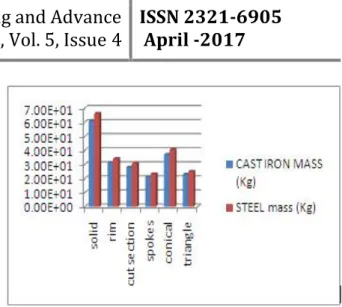
Fig 5.1: mass of flywheels
The above figure shows mass of flywheels, in this spokes type and triangle shape flywheels shows minimum mass as compared to remaining
Fig 5.2: displacements of flywheel
From the above figure, maximum deflection is developed in rim type flywheel when using cast iron or steel. This will be minimized in spokes type flywheel and triangle shape flywheel shows minimum deflection in both materials
Fig 5.3: specific energies of flywheels on basis of geometry at speed 750 rpm
From above figure specific energy storage in flywheels is an approximately same in both materials of flywheel and more energy delivering capacity consist in spokes type flywheel
0 0.0005 0.001 0.0015 0.002 0.0025
so
lid rim
cu
t s
ec
tio
n
sp
ok
es
co
nic
al
tria
ngle
CAST IRON DISPLACEMENT ( mm)
STEEL
DISPLACEMENT (mm)
0 20 40 60 80 100
so
lid rim
cu
t s
ec
tio
n
sp
ok
es
co
nic
al
tria
ngle
CAST IRON SPECIFIC ENERGY (J/Kg) STEEL
Fig 5.4 specific energies of flywheels on basis of
geometry shape factor at speed 750 rpm
From above figure specific energy storage in flywheels is an approximately same in both material of flywheel and more energy delivering capacity consist in cut section type flywheel and then spokes type flywheel have more energy delivering capacity as compared to remained per minimum material.
Fig 5.5: von mises stress
From the above figure, maximum stress is developed in steel flywheel as compared to cast iron flywheels and maximum stress observed in cut section flywheel as compared to remained flywheels
Table no 5.3 shows maximum speeds of flywheel with factor of safety
From above table shows maximum speeds of flywheels with factor of safety and maximum energy storage per unit mass and it is more in triangle (leval) shape flywheel at higher speeds as compared to remains.
CONCLUSION:
Different type of flywheels are designed and analyzed for getting high reliability and long life. Smart design of flywheel geometry has significant effect on its specific energy performance. Amount of kinetic energy stored by spokes flywheel is greater than any other flywheel at 750 rpm from analysis results, the material induced in the spokes flywheel is less than that of other flywheel, thus reduce the cost of the flywheel. From the analysis it is found that maximum stresses induced are in the rim and arm junction. And according to the shape factor cut section flywheel shows maximum energy storage for unit mass at 750 rpm but stresses induced in flywheel is more than other flywheels.
Results shows that efficient flywheel design maximize the inertia of moment for minimum material used and guarantee high reliability and long life. And then I found maximum speed of flywheels with factor of safety at which it is operate the results shows triangle shape (leval) flywheel operates at maximum speed and stores maximum energy per unit mass is more as remain flywheels and mass of flywheel is less as compared to solid, rim, cut section and conical
flywheels and 1 or 2 kg’s more than spokes flywheel.
REFERENCES
[1]. Bawane G ―Analysis and optimization of Flywheel ijmerr/vol.1/no.2/july2012, pp272-276.
[2]. Bolund B, Bernhoff H, Leijon M -Flywheel energy and power storage systems / Renewable and Sustainable Energy Reviews 11 (2007) 235–258.
[3]. Bitterly G, “Flywheel technology: past, present, and 21st century projections,” IEEE Aerospace and Electronic Systems Magazine, vol. 13, no. 8, pp. 13–
16, 1998.
[4]. Dhengle M ―Investigation of stresses in arm type
rotating flywheel IJEST/vol.4/pp641-650.
[5]. Forrester, A. I.& Keane, A. J. (2009). Recent advances in surrogate-based optimization, Progress in Aerospace Sciences 45(1-3): 50–79.
0 100 200 300 400 500
so
lid rim
cu
t s
ec
tio
n
sp
ok
es
co
nic
al
tria
ngle
CAST IRON SPECIFIC ENERGY (J/Kg) STEEL SPECIFIC ENERGY (J/Kg)
0.00E+00 1.00E+06 2.00E+06 3.00E+06 4.00E+06 5.00E+06
6.00E+06 CAST IRON
[7]. Mofid M―An Optimal Two-Dimensional Geometry of Flywheel for Kinetic Energy Storage Int. J. of Thermal & Environmental Engineering Volume 3, No. 2 (2011) 67-72
[8]. Sudipta S ―Computer aided design & analysis on
flywheel for greater efficiency IJAERS/Vol. I/ Issue II/299-301 International Journal of Mechanical Engineering and Research, ISSN 0973-4562 Vol. 5 No.1 (2015) © Research India Publications; http://www.ripublication.com/ijmer.htm 13
[9]. A Summary of the State of the Art of Superconducting Magnetic Energy Storage, Systems, Flywheel Energy Storage Systems and Compressed Air Energy Storage Systems. Sandia Report, SAND99 - 1854, July 1999.