HAL Id: hal-02161803
https://hal.archives-ouvertes.fr/hal-02161803
Submitted on 21 Jun 2019
HAL
is a multi-disciplinary open access
archive for the deposit and dissemination of
sci-entific research documents, whether they are
pub-lished or not. The documents may come from
teaching and research institutions in France or
abroad, or from public or private research centers.
L’archive ouverte pluridisciplinaire
HAL, est
destinée au dépôt et à la diffusion de documents
scientifiques de niveau recherche, publiés ou non,
émanant des établissements d’enseignement et de
recherche français ou étrangers, des laboratoires
publics ou privés.
Standards and Applications
Ali Nikoukar, Saleem Raza, Angelina Poole, Mesut Günes, Behnam Dezfouli
To cite this version:
Ali Nikoukar, Saleem Raza, Angelina Poole, Mesut Günes, Behnam Dezfouli. Low-Power Wireless for
the Internet of Things: Standards and Applications: Internet of Things, IEEE 802.15.4, Bluetooth,
Physical layer, Medium Access Control, coexistence, mesh networking, cyber-physical systems, WSN,
M2M. IEEE Access, IEEE, 2018, 6, pp.67893-67926. �10.1109/ACCESS.2018.2879189�. �hal-02161803�
Low-Power Wireless for the Internet of Things:
Standards and Applications
ALI NIKOUKAR 1, SALEEM RAZA1, ANGELINA POOLE2, MESUT GÜNEŞ1, AND BEHNAM DEZFOULI 2
1Institute for Intelligent Cooperating Systems, Otto von Guericke University Magdeburg, 39106 Magdeburg, Germany 2Internet of Things Research Lab, Department of Computer Engineering, Santa Clara University, Santa Clara, CA 95053, USA
Corresponding author: Ali Nikoukar ([email protected])
This work was supported by DAAD (Deutscher Akademischer Austauschdienst) and DAAD/HEC Scholarships.
ABSTRACT The proliferation of embedded systems, wireless technologies, and Internet protocols have
enabled the Internet of Things (IoT) to bridge the gap between the virtual and physical world through enabling the monitoring and actuation of the physical world controlled by data processing systems. Wireless technologies, despite their offered convenience, flexibility, low cost, and mobility pose unique challenges such as fading, interference, energy, and security, which must be carefully addressed when using resource-constrainedIoTdevices. To this end, the efforts of the research community have led to the standardization of several wireless technologies for various types of application domains depending on factors such as reliability, latency, scalability, and energy efficiency. In this paper, we first overview these standard wireless technologies, and we specifically study the MAC and physical layer technologies proposed to address the requirements and challenges of wireless communications. Furthermore, we explain the use of these standards in various application domains, such as smart homes, smart healthcare, industrial automation, and smart cities, and discuss their suitability in satisfying the requirements of these applications. In addition to proposing guidelines to weigh the pros and cons of each standard for an application at hand, we also examine what new strategies can be exploited to overcome existing challenges and support emergingIoT
applications.
INDEX TERMS Internet of Things, IEEE 802.15.4, Bluetooth, Physical layer, Medium Access Control,
coexistence, mesh networking, cyber-physical systems, WSN, M2M I. INTRODUCTION
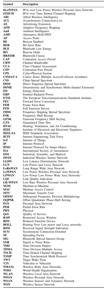
The Internet of Things (IoT) [1] refers to the inter-networking of everyday objects that are equipped with sensing, com-putation, and communication capabilities. These networks can collaboratively interact and perform a variety of tasks autonomously. IoT promises to play a remarkable role in diverse application domains, such as smart homes [2], med-ical care [3], [4], industrial automation [5], [6], intelli-gent transportation [7], [8], resource management [9], smart cities [10], [11], and energy management [12], [13], as shown in Figure 1. For example, in a smart home application, based on user prescribed settings, different monitoring and control tasks are carried out by smart sensors and actua-tors, such as the heating control system, air-condition mon-itoring, and fire alarms. Closely related to the IoT are
Machine-to-Machine(M2M)communication [14],Wireless
Sensor Networks (WSNs)[15],Wireless Personal Area
Net-works (WPANs) [16] Wireless Sensors and Actuators Net-works (WSANs) [17], [18], and Cyber-Physical Systems (CPSs)[19], [20], which are application-dependent terms.
FIGURE 1. Applications ofIoTin different domains.
The entire vision of the IoT surrounds the concept of communication among smart objects, enabling them to see, hear, think, act, and talk to one another to make smart deci-sions. It fundamentally embeds intelligence into the objects 2169-35362018 IEEE. Translations and content mining are permitted for academic research only.
by utilizing ubiquitous computing, networking technologies, inter-networking protocols, and applications [21]. Both wired and wireless networks are utilized to support information exchange at the backbone and local access networks. The local access networks, in particular, are wireless, support multi-hop communication, and enable mobility [22]. As these networks are usually low-power and unreliable, they are referred to asLow-Power and Lossy Networks (LLNs)[23]. These networks lay the necessary foundation of IoT and contribute to making it highly accessible. The aspect of ubiq-uitous accessibility of services and objects to mobile users is imperative because most of theIoTservices are targeted to mobile users. Another strong aspect is the autonomous oper-ation, where IoThelps to decentralize the decision-making process to accomplish autonomous operations with minimal human intervention. This autonomous feature is of paramount importance for a multitude of industrial applications that enable smart processes and systems. This has amplified the vision of the fourth Industrial revolution, also known as the Industry-4.0 or smart factory [24].
Although IoT promises to revolutionize several appli-cation domains and enormously transform the way we live and communicate, it imposes challenging requirements from the networking point of view. The first essential requirement isreliablewireless network connectivity, which is particularly important for applications such as industrial process automation and control, healthcare, emergency sit-uations, disaster recovery, home safety [25]. Second, time-liness or low latency are requirements that guarantee the bounded and deterministic delay of data transfer between different objects so that actions are performed on time. For example, industrial process control systems require real-time communication between machines and controllers. Third, the
low-power operationrequirement helps the nodes save power and avoid unnecessary communication attempts, thereby pre-venting early death and extending network lifetime. All of these requirements led to the development of several standards and technologies. These standards propose differ-ent features and protocols to satisfy the Quality of Service
(QoS)requirements of differentIoTapplications. However, the practical use of these standards in different IoT appli-cations has resulted in several limitations. These limitations accelerated the need for further analysis in order to seek viable solutions to meet existing and future demands ofIoT
applications. In this paper, we review the existing low-power wireless standards and technologies. We primarily focus on
thePhysical(PHY) andMedium Access Control(MAC)
lay-ers because they directly impact several performance metrics, such as reliability, latency, scalability, and energy consump-tion. In this paper:
– We present an overview of some of the active stan-dardization bodies that are working on the devel-opment of sophisticated standards and protocols forIoT.
– We discuss and analyze several low-power wireless standards and technologies. The Institute of
Electri-cal and Electronic Engineers (IEEE) 802.15.4
stan-dard and its derivations such as Thread, WirelessHART,
IPv6 over Low Power Wireless Personal Area Network
(6LoWPAN), and IPv6 Over TSCH(6TiSCH)are pre-sented. We also study the Bluetooth standard and its variants, such as Bluetooth Basic Rate and Enhanced
Data Rate(BR/EDR)andBluetooth Low Energy(BLE).
– Various technologies and standards that share common frequency bands, such asIndustrial, Scientific, and Med-ical(ISM), generate severe interference in a coexisting environment. We investigate how the inherentPhysical
(PHY)andMedium Access Control(MAC)layer design of these standards and technologies help to cope with interference issues.
– We explore the suitability of various standards across differentIoTapplication domains, such as smart homes, smart cities, smart healthcare, and industrial automation. Possible limitations of each standard in different appli-cation domains are also highlighted.
– We emphasize the need to overcome the limitations of the existing standards to meet timeliness, reliability, scalability, and energy efficiency requirements ofIoT
applications.
– We explain how the stringent requirements of IoT
applications and the constrained resources of objects introduce severe challenges in terms of protocol design.
The remainder of the paper proceeds as follows. In Section III, we discuss IEEE 802.15.4, in particular, its PHY and MAC features. Several standards based on IEEE 802.15.4 are also presented. Subsequently, we dis-cuss how IEEE 802.15.4e overcomes the limitations of IEEE 802.15.4. SectionIVdescribes Bluetooth and its radio and link layer working principles in detail. The discus-sion revolves around different verdiscus-sions of Bluetooth such as BR/EDR and BLE. Specifically, we demonstrate the communication principles in BLE such as beaconing and extended connectivity features. Additionally, we point out the limitations of each of the Bluetooth versions. Furthermore, we explain theBLEmesh specification. SectionVpresents the coexistence perspective of different standards and tech-nologies that share the 2.4 GHz band. Other non-standard sources of interference are also described. In Section VI, we give an overview of the Z-wave standard. Section VII
examines IEEE 802.11ah, which is another low-power wire-less standard operating in sub-GHz. In SectionVIII, theLong
Range(LoRa)technology is presented. In SectionIX, we
dis-cuss broad applications of IoT and their characteristics, requirements, and traffic categories. We explore the suitabil-ity of each standard relative to these application domains. In Section Xwe discuss the existing surveys relevant to IoT. Finally, a conclusion is drawn in SectionXI.
II. STANDARDIZATION BODIES
A large number of devices from different technologies and vendors makes the IoT environment quite heteroge-neous, which causes interoperability issues across different application domains. To meet this challenge, we witness several standardization bodies that accelerated the devel-opment of low-power wireless standards and technologies. These standards employ unique PHY,MAC, network, and application layer enhancements to meet power, low-latency, high reliability, scalability, and security requirements ofIoTapplications. In the following, we describe some of the well-known standardization bodies that are actively working toward developingIoTprotocols.
IEEE Standards Association(IEEE-SA) [26] is the most
well-known standardization organization. It mostly targets the lower layers in the OSI protocol stack, namely MAC
and PHY. In this paper, we focus on IEEE 802.15.4, IEEE 802.15.1 (Bluetooth), and IEEE 802.11ah due to their low power operation. The IEEE 802.15.4 provides the fun-damental blocks for many of the key technologies such as ZigBee, Thread, WirelessHART, and ISA100.11a. These standards are detailed in SectionIII. Up to 2017, IEEE-SA has published more than 1100 active standards, and it has more than 600 standards under development [27].
ZigBee alliance [28] is an open global standard based on IEEE 802.15.4 that is targeted to low-power wireless net-works. The technical specifications of ZigBee are discussed in SectionIII. The most common applications of ZigBee are in home automation, industrial control, and healthcare. They will be described in SectionIX.
TheInternet Engineering Task Force (IETF)[29] is one
of the non-profit organizations that developed IoT standards such as6LoWPANorRouting Over Low power and Lossy
networks(ROLL).IETFencourages more people to
commu-nicate and collaborate on new ideas such as improving the
IoTuse cases in smart cities, healthcare, industrial Internet and other related applications by providing solutions to over-come issues such as scalability, timeliness, and IPv6 adap-tation for low-power wireless networks. IETF provides a platform where developers and researchers can collaborate voluntarily to improve and build standards. The standard documents provided by the IETF, such as the Request for Comments (RFCs), can be accessed freely. For example, (RFC4944) [30] was developed in 2007 and updated by the drafts (RFC6282) [31], (RFC6775) [32], (RFC8025) [33], (RFC8066) [34] up until 2017 for developing 6LoWPAN
standards. These documents cover a wide range of topics relating to issues of routing, security, and applications inIoT.
The European Telecommunications Standards
Insti-tute (ETSI) [35] is another non-profit body (like IETF) that works for standardization organizations in Europe. It produces globally-applicable standards for communication technologies for the Internet, such as fixed, mobile, and broadcast, and short-range technologies. The Third Gener-ation Partnership Project(3GPPTM) is an example of the
ETSIstandards. Currently,ETSIhas 800 member organiza-tions from 67 countries.
OneM2M [36] is a worldwide organization formed in 2012 that aims to provide and develop technical specifications in order to meet architectural, security, and interoperabil-ity requirements forM2Mcommunication. It targets appli-cations such as smart cities, smart grids, smart homes, and healthcare. OneM2M cooperates with more than 200 companies.
International Society of Automation (ISA) [37] targets
industrialIoTcovering applications such as security, safety, batch control, and enterprise integration. A widely-adopted standard developed by this body is ISA100.11a [38].ISAhas more than 40,000 members and 140 committees, subcom-mittees, working groups, and task forces that are working to develop the ISA standards.
OpenWSN [39] is a project created by the University of California, Berkeley. It aims to provide an open source plat-form for developers and researchers to implement the IoT
protocol stack. The stack implements different hardware and operating systems, such as OpenMote [40] and RIOT [41], respectively. One of the important goals of OpenWSN is the adaptation of theTime-Slotted Channel Hopping(TSCH)
concept over IEEE 802.15.4e.TSCHprovides the IPv6 sup-port in the network layer based on theIETF 6TiSCH imple-mentation [42]. We will discussTSCHin SectionIII-H.
Internet Protocol for Smart Object(IPSO)alliance [43] is
an active organization for enablingInternet Protocol(IP) con-nectivity for smart object communication inIoT.IPSOwas founded in 2008 and targetsIoTapplications, such as smart cities, home automation, healthcare, and energy management.
Bluetooth Special Interest Group(SIG)[44] developed and
licensed Bluetooth technology. It is a non-profit organization that was founded in September 1998. This body publishes the core specifications for the different version of Bluetooth. In SectionIV, we will describe the different versions of Blue-tooth developed bySIG. Currently,SIGis supported by more than 30,000 member companies [45]. AlthoughSIGdoes not sell any Bluetooth products, it owns the Bluetooth word mark, figure mark and combination mark, which collectively make up the Bluetooth trademarks.
III. IEEE 802.15.4
IEEE 802.15.4 [46], which mainly defines PHYandMAC
layer specifications, is considered the defacto standard for
Low Rate Wireless Personal Area Network(LR-WPAN). The
standard was developed for low data rate monitoring and control applications that require very low power consump-tion. Due to its appealing features such as low-power, low cost, and moderate data rate, it is the most widely used stan-dard for home automation [47], industrial automation [48], [49], smart cities [50], and Wireless Body Area Networks
(WBANs)[51]. Most of the existing standards, such as Zig-Bee [28], WirelessHART [52], and ISA100.11a [53], employ IEEE 802.15.4 as the PHYlayer technology together with certain upper layer modifications. At the MAC layer, the
FIGURE 2. The star and peer-to-peer network topologies supported by the IEEE 802.15.4 standard.
TABLE 2.Frequency bands of the IEEE 802.15.4 standard.
standard offers a flexible protocol that tries to achieve a better trade-off among several performance metrics, such as energy efficiency, delay, coverage, and data rate.
The IEEE 802.15.4 network supports star, tree, and peer-to-peer network topologies as shown in Figure2. The network is composed of two types of devices, namelyFull Function
Device (FFD) and Reduced Function Device (RFD). The
FFDscan perform activities like network coordination, rout-ing, and sensrout-ing, whereas theRFDsare constrained nodes that can only serve as end-devices to perform sensing tasks. As coordinators, FFDs can form, manage, and maintain a
Personal Area Network(PAN), but aFFDcan manage only
a singlePANat a time. TheFFDscan also serve as routers that relay traffic through intermediate routes from source to destination. They can also store routing tables.
The following discussion elaborates more on thePHYand
MAClayer specifications of the standard. A. PHY LAYER
The PHY layer uses the 2.4 GHzISM[54] frequency band. Different frequency bands are allocated to different regions, as listed in Table2.
The PHY offers services such as the transmission and reception ofPHY Protocol Data Units(PPDUs) across the physical channel. It performs a number of suitable function-alities like the activation and deactivation of radio transceiver,
Energy Detection(ED),Link Quality Indication(LQI),Clear
Channel Assessment (CCA), channel frequency selection,
and packet transmission and reception [46].
The purpose of the ED is to estimate the power of the received signal within the bandwidth of the channel so that theMAClayer can avoid interference.
CCA is a reliable method to determine any activity on the channel before making a transmission. CCA works based on multiple sampling of channel energy. For exam-ple, it may sample the channel five times and report a free
channel if there is at least one sample less than the noise floor. There are total 27 different channels available across all of the bands as defined by the IEEE 802.15.4 stan-dard. For example, the 2.4 GHz band includes 16 channels numbered from 11 to 25, where each channel has a bandwidth of 2 MHz and center frequencies are separated by 5 MHz. They offer an achievable data rate of as much as 250 kbps [55]. IEEE 802.15.4 uses Direct Sequence Spread
Spectrum (DSSS) which mainly supports coexistence by
spreading the signal over a larger bandwidth.
Upon receiving a request from the MAC sub-layer, the radio transceiver may operate in one of the three states: transmit, receive, or sleep. The energy consumption states of a transceiver can be classified into the following states: transmission, reception, and sleep. During idle listening, the device is listening to incoming packets, which may result in overhearing packets that are not destined for it [56]. It is observed that in most of the commercial IEEE 802.15.4 com-pliant transceivers the energy consumed during idle listening is almost the same as receiving or transmitting a packet [57] and is a significant cause of energy waste. For example, the TI CC2420 transceiver at 0 dBm output power con-sumes 17.4 mA in transmission and 18.8 mA in idle listening states [58].
Since nodes have constrained resources, the IEEE 802.15.4 implements duty cycling in theMACprotocol to save power. Duty cycling allows a node to sleep by turning off its transceivers to conserve energy periodically.
B. MACLAYER
The standard proposes a flexibleMACthat can mainly switch between two channel access modes known asbeacon enabled
mode andnon-beacon enabledmode. 1) BEACON ENABLED (BE) MODE
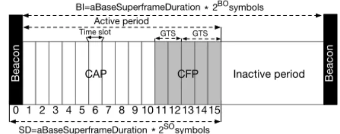
In this mode, communication is based on a superframe struc-ture. The superframe starts with a beacon period followed by an active period and an inactive period, as shown in Figure3. The active period consists of theContention Access Period
(CAP) and Contention Free Period (CFP), while the inac-tive period allows duty cycling. The acinac-tive period is further subdivided into 16 equally spaced parts called time slots. The superframe information is broadcasted through beacons at the start of the network. A beacon is a specific frame generated periodically by the PAN coordinator to update syn-chronization and other network related information among the nodes. A superframe is bounded by two beacons. After the beacon, theCAPimmediately starts where nodes compete, using slottedCarrier Sense Multiple Access/Collision Avoid-ance(CSMA/CA) to transmit new packets to the coordina-tor or request pending packets. To minimize the probability of collisions over the channel, slotted CSMA/CA uses the
Binary Exponential (BE) Backoff algorithm. After theCAP
is the CFP, which contains Time Division Multiple Access
(TDMA) like Guaranteed Time Slots (GTSs)for transmis-sion. GTSs are allocated by the coordinator to the nodes that
FIGURE 3. The superframe structure of the BE MAC mode of IEEE 802.15.4 standard.
require special bandwidth reservations [59]. Nodes request the GTSs from the PAN coordinator during theCAP. GTS can be used either for transmission or reception, and a maximum of seven GTSs are allowed per superframe. During the GTS, the node has exclusive access to the channel at its disposal.
The total duration of the superframe, including active and inactive periods, can be configured through two important parameters known as Superframe Order (SO) and Beacon Order(BO). The network coordinator defines the superframe structure by aBeacon Interval(BI), which is the time between two sequential beacons, and a Superframe Duration (SD), which is the active duration of the superframe, as shown in Figure3. The values of BO and BI are related as follows [46];
for 0≤ BO≤14
BI =α×2BOsymbols
αis known asaBaseSuperframeDuration, which is the num-ber of symbols forming a superframe when the SO is equal to zero. The SO defines the duration of the active period including the beacon frame. The values of SO and SD are related as follows:
for 0≤SO≤BO≤14 SD=α×2SOsymbols
Therefore, in the case of 2.4 GHz, the value of SD=15.36× 2SO ms with a BI = 15.36×2BO ms. Thus, the value of BI can be adjusted between 15 ms to 245 s [59], depending on the value of BO and SO.
2) NON-BEACON ENABLED (NBE) MODE
No GTS allocation is employed in this mode. Nodes mainly utilize unslottedCSMA/CAfor channel access and perform only a single CCA operation without synchronization to backoff boundaries [60].
C. LIMITATIONS OF IEEE 802.15.4 MAC
Although IEEE 802.15.4MAChas several appealing features for general IoT applications, yet it has several limitations for applications that require high reliability, low latency, and energy efficiency, as pointed out in [61] and [62]. To address this issue, several investigations on the performance analysis of IEEE 802.15.4MACwere conducted [63]–[66].
Studies in [67] show that the selection of the binary expo-nent is random and does not take into account the number of available nodes, the communication activity level, or the priority of data packets, resulting in a higher likelihood of collisions. The random nature of the binary exponent causes nodes to sleep for prolonged periods than required. This leaves the medium unnecessarily idle for an extended period, impacting the throughput.
A simulation-based evaluation of slotted Carrier Sense
Multiple Access(CSMA)for beacon-enabled mode for dense
networks was conducted in [66]. The authors showed that the backoff algorithm is not flexible for large-scale networks, since the lower limit of the backoff delay is always 0 which is fixed. Thus, it prevents particular ranges for the backoff delays. Therefore, it is not sufficient to avoid collisions for large-scale networks. The impact on the selection of the BO and SO was analyzed based on the average delay. A node that cannot complete its data transmission in the currentCAPis forced to defer its transmission to the following superframe. Therefore, the node has to re-contend to access the medium and face collisions. Such a situation makes the delay for the data transmission not only non-deterministic and unbounded, but it also deteriorates the throughput.
Another study on the performance of slotted CSMA/CA
for the BE mode was conducted in [63]. The authors showed that the default values of MAC parameters, such as MAC
minimum binary exponent and number of backoffs, may result in lower throughput and high-power consumption. This analytical study was based on the Markov model for both sat-urated and unsatsat-urated periodic traffic, and it was suggested to tune theMACparameters to achieve better results.
Anastasiet al.[64] gave a comprehensive analysis on the
MAC unreliability problem. The authors argued that if the power management is enabled, it will result in poor packet delivery ratio. The reason was found to be the contention access period and its default parameters, such as the minimum and maximum binary exponent value, the maximum number of backoffs, and maximum frame retries allowed.
The authors suggested that theMAC, in its current form, is not suitable for mission-critical applications and requires proper tuning of theMACparameters for better performance. Motivated by these shortcomings, several relevant stan-dards and protocols emerged to overcome the limitations of IEEE 802.15.4MAC[68], [69]. We overview these protocols and standards as follows. We will present different applica-tions based on this standard and elaborates further on their suitability in each application domain in SectionIX.
D. THREAD
Thread [70] is an open networking stack, which has received support from well-known organizations such as Google, Sam-sung, Nest, Freescale, and ARM [71]. It is built on top of the IEEE 802.15.4PHYandMAClayer specifications, operating in 2.4 GHz band. It is cost-effective, reliable, secure, works at very low-power, and supports up to 250 devices in a single local mesh network. The technology is optimized for
FIGURE 4. The mesh networking architecture of Thread.
low latency (less than 100 ms) and smart home networking applications, such as access control, energy management, and light control.
It does not suffer from a single point of failure due to its mesh networking capability, thus improving reliability.
It natively supports 6LoWPAN technology to benefit IPv6 capability in order to support interoperability. In this way, devices can be directly connected to the Internet and can be accessed from anywhere. Figure4shows the mesh network architecture of Thread. As shown, a typical Thread network consists of at least one or more border routers, a router, a leader, sleepy end-devices, and end-devices. The border router serves as a gateway that is responsible for connect-ing a Thread network to an adjacent non-Thread network that operates on other physical layers like IEEE 802.11 or Ethernet. Multiple border routers can be deployed to achieve redundancy. This keeps the mesh network functional in case of a failure of the single border router, thereby improving resiliency. A router offers routing services to the network devices. It also provides security and network joining services for the devices that wish to join the network. A router or bor-der router can act as a leabor-der which is required to make decisions for some specific functions like assigning router addresses and allowing new router requests.
Sleepy end-devices can communicate through their parent router and serve as only host devices, but they cannot for-ward messages for other devices. End-devices can exchange messages with their parent devices. At the application layer, Thread does not impose any particular application layer pro-tocol, however, the common light-weight protocols, such as
Constrained Application Protocol(COAP),Message Queue Telemetry Transport(MQTT), andExtensible Messaging and Presence Protocol(XMPP), can be used.
The standard implements several security enhancements; it supportsTransport Layer Security(TLS) [72] and its variant, Datagram TLS (DTLS) [73]. A network-wide key is used at the MAC that protects the IEEE 802.15.4 data frames against eavesdropping, tampering, and targeted disruption from outsiders.
Since Thread and ZigBee mostly share the same physical specifications and have several features in common, it is expected that they are likely to merge in order to create a uniformIoTstandard [74]. Although Thread claims to have all of the features mentioned above, there are no practical implementations or deployments available based on Thread standard.
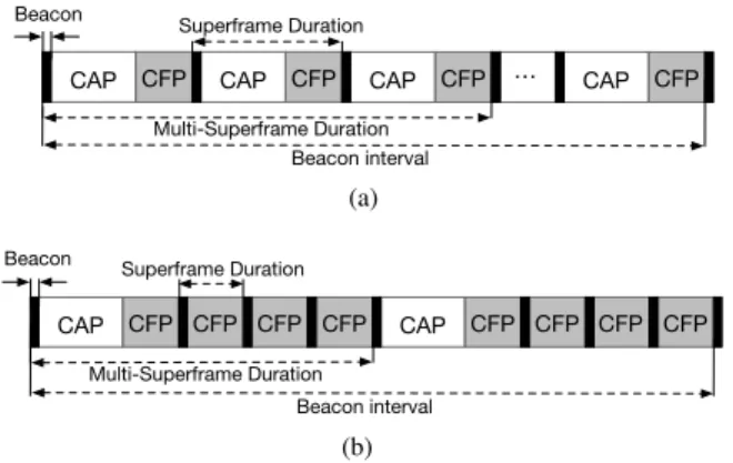
FIGURE 5. The multi-superframe structure of DSME MAC mode with extended and reduced CAP. The shaded bars show the CFP consisting of GTSs and the white bars show CAP. (a) DSME multi-superframe with extended CAP. (b) DSME multi-superframe with reduced CAP.
E. IEEE 802.15.4E
IEEE 802.15.4, in its 2011 version [46], supports enhanced physical specifications that enable a variety of applica-tions (see sectionIII-A). However, the standard cannot sup-port mission-critical applications due to several limitations. Specifically, in order to meet reliability, low latency, and low-power consumption, which are the requirements of emerg-ing applications like Cyber Physical System (CPS) based
Intelligent Transportation System (ITS) [75], [76], smart health care [77], and industrial process automation and control, IEEE released an enhanced version known as the IEEE 802.15.4e [78].
It specifically introduces five enhancedMACprotocols in the form of MACbehavior modes. These protocols will be elaborated in the subsequent discussion.
1) DETERMINISTIC AND SYNCHRONOUS MULTI-CHANNEL EXTENSION (DSME)
DSME is an extension of the beacon-enabled MAC mode of the IEEE 802.15.4. DSME does not rely on a single channel. Instead, it uses multiple channels and has a multi-superframe structure, which has an extended number of GTSs. A multi-superframe consists of a collection of consec-utive non-overlapping superframes as shown in Figure5. The multi-superframe structure can flexibly support both periodic and a periodic traffic. DSME mainly targets multi-hop net-works and usesEnhanced Beacons(EBs), which are shown as black bars inside the multi-superframe in Figure 5. EBs are used to announce the presence of the network and contain information related to the size of the time slots, slot frames, and time synchronization information to maintain synchro-nization among the network nodes. The superframe consists of only the active period, which is further subdivided into
CAPandCFP. Nodes in theCAPuse slottedCSMA/CAfor channel access to transmit monitoring, urgent, or a periodic data. TheCAPis fixed to 8-time slots during which the nodes should stay awake. The CFPoccupies the remaining seven slots that are known as the Guaranteed Time Slots(GTSs)
(DSME-GTSs), which are used to transmit time-critical data. As mentioned before, nodes remain awake during the CAP; however, in order to save energy, DSME reduces the num-ber of CAP periods, and only the first superframe of each multi-superframe uses theCAP. The rest of the superframes inside the multi-superframe structure do not make use of the
CAP, but rather the whole period is treated as a CFPthat consists of 15 GTSs, as shown in Figure3 (SectionIII-B). DSME exploits channel diversity to select the best possible channel in order to ensure reliability and robustness against external interference and multi-path fading. Therefore, it is particularly suitable for factory automation, smart metering, and patient health monitoring.
DSMEMACmode is scalable due to its distributed nature. Specifically, slot allocation and beacon scheduling are not performed by a central entity, but rather they are performed by the network devices themselves in a distributed fashion. It is adaptive to time-varying traffic conditions and to changes in network topology, where each pair of nodes, based on their needs, allocates and deallocatesGTSslots. Due to its adaptive capability, it can be a good candidate for mobile networks, where data rate requirements and topology vary over time. It improves energy efficiency through its Group Acknowl-edgement(GACK) option, where a singleAcknowledgement
(ACK)frame aggregates the acknowledgments of multiple data frames.
Although DSMEMACpresents significant enhancements, some of its shortcomings have been identified as follows. For example, Rodenas-Herraiz et al. [79] pointed out the overhead of topology change in large-scale networks. In par-ticular, the overhead may be high due to the rescheduling of beacon frames and/or selection of non-interfering frequency channels, assuming the multi-superframe structure is long enough and contains superframes of all coordinators. This increases the energy expenditure of the devices. On the other hand, in a dense network, DSME incurs considerable delays due to theTDMAmulti-superframe structure, where the coor-dinator and the devices become active only in their respec-tive superframes. Therefore, if the part of data transmission cannot be completed in the current superframe, it needs to be deferred to the following superframe. The coordinator and its associated devices would have to wait for the next multi-superframe to resume their transmission.
2) THE LOW LATENCY DETERMINISTIC NETWORK (LLDN) LLDN targets applications that require low latency, such as manufacturing and robotics. It only works with the star topology and usesTDMAsuperframe time slots with small packets. The duration of the superframe is fixed and has distinctive slots, namely the beacon, management, uplink, and bidirectional time slots. The duration of a time slot is 10 ms, and the number of time slots determines the num-ber of devices that can communicate. Since the size of the superframe is restricted to a certain number of time slots, it only allows a certain number of devices to participate in the network.
However, in order to make the network scalable up to more than 100 devices, the PAN coordinator can use mul-tiple transceivers that each operate on a different frequency. Moreover, in order to further reduce latency, LLDN makes use of short MAC addresses to decrease frame processing and transmission time. Similar to DSME, it also exploits the GACK mechanism to minimize the bandwidth overhead. The use of star topology makes LLDN more suitable for factory automation, where a large number of nodes often communi-cate with a central entity. However, it has some limitations in terms of scalability, topology, and throughput.
The standard recommends using multiple transceivers in the PAN coordinator to create various networks operating on different channels. However, a study by Pattiet al. [80] argues that this recommendation imposes a higher cost and greater complexity. They propose multi-channel LLDN, which improves scalability by allowing a higher number of nodes in the network while maintaining low cycle times with-out the need of multiple transceivers for the PAN coordinator. Bergeret al. [81] indicate that using a star topology restricts coverage.
They propose the extension of the star topology, which is to collect data from two-hop sensors with the use of a relay node strategy. The relay nodes improve transmission reliability by retransmitting undelivered packets. The authors are of the view that the use of reserved slots and retransmission strategy in default LLDN reduces the number of sensor nodes per network, which impacts data throughput.
3) THETime-Slotted Channel Hopping(TSCH)
TSCH MAC is considered one of the latest generations of
MAC protocols in the category of reliable and low-power operation. It aims to satisfy the requirements of low-power mesh networks in industrial process automation. TSCH is considered the most viableMACcandidate for theIoT pro-tocol stack because of its time and channel diversity fea-tures [82]. It incorporates mechanisms such as time-slotted access and multiple channel communication with channel hopping. Time-slotted channel access inherently avoids the nodes that are competing for the channel, eliminating colli-sions and improving throughput. It provides every network node guaranteed access to the wireless medium, offering deterministic latency, and builds on a communication sched-ule that coordinates the exchange of information among the nodes. In this way, each node exactly knows when to transmit, receive, or sleep. TSCH achieves low-power through syn-chronization, causing the receiver to be active precisely when the sender transmits.
The improved design of TSCH is influenced by Time
Synchronized Mesh Protocol(TSMP)which is a proprietary
MACprotocol designed by the Dust Networks [83].TSMP
became the widely acceptedMACprotocol in the industrial domain, and in particular, is adopted by WirelessHART [84] for itsMACoperation [52]. Standards like ISA100.11a [53] and WIA-PA [85] use the core concepts of TSMPin their
MAC design, alongside some higher layer packet format
FIGURE 6. TSCH slotframe schedule based on the associated topology. (a) TSCH slotframe, it also shows sequence of transmission events within a timeslot for a transmitter-receiver node pair. (b) The associated topology where dotted arrows show transmission in shared slots and solid arrows represent transmission in dedicated slots.
modifications. Below, we present an overview of the TSCH slot frame and its functionality.
The earlier MAC protocol of IEEE 802.15.4 (see sectionIII-B) used a single channel approach in combination with the backoff algorithm in order to avoid collisions in a shared medium.TSCH takes a multi-channel approach by utilizing channel hopping and maintaining a low duty cycle. Channel hopping intelligently mitigates external interfer-ence and multi-path fading [86], which makesTSCHhighly reliable and robust. Today, TSCH commercial products offer 99.9% end-to-end reliability while consuming an aver-age current that is below 50µA at 3.6 V [87].
TSCHSlotframe:A slot frame combines several time slots that repeat periodically, as shown in Figure 6a.
Not only does this periodic repetition of slot frame provide each node the opportunity to communicate in the network, but it also helps to update synchronization and other network related information.TSCHdoes not define and impose a slot frame size; instead, the slot frame size is a design parameter that is decided by the application programmer. The size of the slot frame can be from 0 to 1000 time slots [88]. Enhanced beacons are sent by the nodes to advertise the network.
A time slot is long enough to send a maximum size packet and receive its correspondingACK. A typical value of the
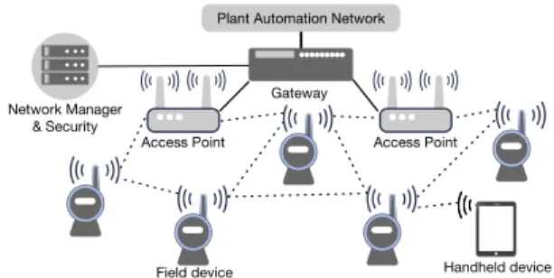
FIGURE 7. WirelessHART network architecture showing communication among different kinds of devices.
time slot duration is suggested to be 10 ms. If an ACK is not received in a defined time period, the retransmission will follow the subsequent time slot that is scheduled for the same (transmitter-receiver) pair of nodes. A possible communica-tion schedule is depicted in Figure 6a. The slot frame is seven slots long, and there are sixteen channel offsets available. Each link is assigned a cell. Some of the cells could be dedi-cated to only one pair of nodes, while others could be shared cells, i.e., more than one pair of nodes can communicate in these slots. There could be a possibility of collision in a shared slot, but the standard implements a simple back-off scheme to deal with it. Each node only cares about the cell it is assigned to. For example, in Figure 6a, when noden5transmits a packet
to noden0, it uses time slot 3 from the dedicated time slots
and channel offset (Ch.05). F. WIRELESSHART
WirelessHART [84] is the first open wireless industrial standard, introduced by the HART (Highway Addressable Remote Transducer) [89] foundation. It is mainly designed for industrial process measurements and control applica-tions while still being backward compatible with the HART legacy systems. It is a mesh network with self-organizing and self-healing capabilities in combination with a secure and reliable communication protocol. Although Bluetooth and ZigBee were prevalent before the release of Wire-lessHART, they could not fulfill the stringent requirements of industrial control applications [52]. Specifically, neither ZigBee nor Bluetooth offered guaranteed end-to-end delay and reliability.
1) NETWORK ARCHITECTURE
WirelessHART introduces different types of devices in the network as shown in Figure7: network and security manager, gateways, access points, and field devices. The network man-ager is responsible for computing and maintaining the com-munication schedule and routing tables, as well as performing the overall network health monitoring. It can query a par-ticular field device through the gateway as requested by the host application. The security manager and network manager work collaboratively to provide security against intrusion and attacks by generating a different session, joint, and network keys [90].
2) PHY ANDMACLAYERS
ThePHYlayer is based on IEEE 802.15.4 [55].
TSMP is the medium access and networking protocol which offers reliable, robust, and low-power communica-tion. It features time synchronized, dedicated time-slotted access, link layer ACKs, graph-based routing, and multi-layer security on every packet. It targets reliability of greater than 99.99% at low-power, scalability of hundreds of mesh nodes, flexibility to support time-varying traffic, security, and the ability to withstand harsh industrial environments [91]. The communication is governed by a time-slotted schedule which lets the nodes know when to transmit, receive, or sleep.
TSMPfollows the same schedule scheme as ofTSCH, where the schedule is computed and is represented through cells using different time slots and channel offsets as described in SectionIII-E3.
G. IPV6 OVER LOW-POWER WIRELESS PERSONAL AREA NETWORKS (6LOWPAN)
The underlying motivation to standardize6LoWPAN [92], [93] was the need to integrate constrained devices to the Internet.IETFcreated the6LoWPANandRouting Over Low-Power and Lossy Networks(ROLL) [23] working groups with the goal toward standardized IP-based protocols for LLN. The ROLL focuses on developing routing solutions forLLNs
over IPv6.
The fact that the IPv6 protocol imposes high overhead and complexity which makes it difficult to be deployed in constrained environments, such as the IEEE 802.15.4 net-work. Since theMACpayload of IEEE 802.15.4 cannot be larger than 127 bytes, the 40-byte header of IPv6 does not leave much space for actual payload. This prompted the need to form an adaptation layer between the network and data link layer in order to enable IPv6 packets to fit into the IEEE 802.15.4 specifications.Low Power Wireless Personal
Area Networks (LoWPANs)impose several constraints, such
as small packet sizes, different address lengths, small band-width, high density of nodes, battery operated devices, poor link quality, and duty cycling. This makes it challenging to develop an optimized adaptation sublayer to successfully map the service required by the network layer on the services provisioned by the link layer [93].
In essence,6LoWPANdefines an adaptation layer through header compression (HC) in order to transmit IPv6 packets over the IEEE 802.15.4 network. It supports packet fragmen-tation and reassembly in order to meet the Maximum Transfer Unit (MTU) requirements of IPv6, and it allows forwarding to the data link layer for multi-hop connections [94].
The 6LoWPAN adaptation layer defines two header compression techniques that compress large IPv6 headers (in the best case) to several bytes. The compression technique, 6LoWPAN-HC1, compresses IPv6 packets that contain IPv6 link-local addresses. The size of the packet is minimized by eliminating fields such as IP version, traf-fic class, flow label, and hop limit. The 6LoWPAN-HC2
FIGURE 8. Envisioned6TiSCHprotocol stack [101].
technique is proposed for the compression of UDP, TCP, and ICMP.
The main objective in proposing the HC1 and HC2 tech-niques was to perform compression in a stateless manner that did not require any previous agreements between the two nodes.
H. 6TiSCH
IETF formed 6TiSCH [95] working group to support IPv6 over TSCH (see Section III-E). 6TiSCH contributes to the IoT by bonding the unique features of TSCH and IP networking mechanisms in order to produce an interop-erable Industrial IoT (IIoT) protocol stack [96]. This will support TSCH MAC being placed under an IPv6 enabled protocol stack running6LoWPAN, IPv6 RPL [97], [98], and CoAP [99], [100]. Figure8shows the reference protocol stack for 6TiSCH [101]. For the successful integration ofTSCH
with upper layer protocols,6TiSCHintroduces a functional entity that is responsible for schedulingTSCHtime slots to be sent on the network. This entity resides at the higher layer and is known as6TiSCHOperation Sublayer (6top).
6top is a logical link control that resides between the IP layer and the TSCH MAClayer. It controls the TSCH
schedule, collects the connectivity graph, and monitors and optimizes the schedule of the cells. It supports both cen-tralized and distributed scheduling approaches. The sched-uled cells are labeled as either hard cells or soft cells. Hard cells cannot be dynamically reallocated by 6top. Rather, they are typically scheduled by a scheduling entity such asPath Computation Entity(PCE), that can move or delete cells in theTSCHschedule. In contrast, soft cells can be reallocated by the 6top dynamically. Typically, a distributed scheduling entity schedules these cells. 6top records the performance of the cells to the same neighbor. If a cell performs poorly com-pared to the other cells with the same neighbor, it moves the cell to a differentchannelOffsetandslotOffset, where chan-nelOffsetandslotOffsetperform better. In this way, the 6top sublayer can cope with the interference reliably.
IV. BLUETOOTH
In this Section, we discuss the history of Bluetooth tech-nology and technical details such as radio, link layer, and network topology. Bluetooth is a low-power wireless tech-nology used for short-range communication. It was designed to replace serial cables with the wireless links [102]. Nowa-days, aside from connecting devices like mice, keyboards, cell phones, headsets, and multimedia devices, it is used to
connect sensors, actuators, controllers, and critical wireless infrastructures. Availability is one of the main advantages of Bluetooth. TheAllied Business Intelligence (ABI)research group predicted that by 2021 there would be 48 billion devices connected to the Internet, 30% of which would be Bluetooth enabled [103]. Bluetooth was introduced in 1999, and the first specification was released in 2001 [104]. In 2002, IEEE assigned the 802.15.1 standard for it [105].
The technology is divided into two major categories: First, Bluetooth Basic Rate and Enhanced Data Rate
(BR/EDR) refers to the earlier versions of Bluetooth mainly designed for file transmission and audio streaming. It is reported that in 2015, 116.32 million BR/EDR headsets were shipped [106]. Second,BLE refers to the recent ver-sions of Bluetooth targeting low-power consumption for
IoT applications. Due to the consumer demand for low-power and high throughput, both BLE and BR/EDR are available in some devices like smartphones and laptops. They are known as dual-mode Bluetooth and switch the proto-col stack from BR/EDR to BLE and vice versa when is needed [107]. Table 4 highlights the key features of each version.
A. BLUETOOTH BASIC RATE AND ENHANCED DATA RATE The first version of BR/EDR was only designed for file sharing by using anAsynchronous Connection-Less(ACL)
link. The link is a single point-to-multiple point link that can be used for broadcasting data and can support both asymmetrical and symmetrical connection. The audio stream-ing capability has been added toBR/EDR by using a
Syn-chronous Connection-Oriented(SCO)link in v1.2. The new
link provides up to three symmetrical point-to-point links that reserve time slots in order to guarantee timely trans-mission. To avoid delay in voice transmission,SCOpackets do not deliver ACKs. In 2003, SIG enhanced the link and released eSCOto improve voice transmission reliability. The higher quality is achieved by employing a limited number of re-transmissions for lost or damaged packets. Additionally, this version employs Adaptive Frequency Hopping (AFH)
to improve coexistence with other wireless protocols [108] (SectionVdiscussesAFHin detail). Bluetooth versions up to v1.2 provide a maximum throughput of 721.2 kbps, known as Bluetooth Basic Rate (BR). Due to the high demand for large file and audio transmission, BR was unable to fulfill the throughput requirements. Therefore, in 2004,SIG intro-duced Bluetooth v2.0 to improve throughput and named it as Bluetooth Enhanced Data Rate (EDR). This version increased the throughput by 2.1 Mbps by using theDifferential Phase Shift Keying(DPSK) modulation technique [109]. Although EDR tries to improve the data rate, it does not satisfy the entire user requirements. Thus, in April 2009,SIGlaunched Bluetooth v3.0, known as Bluetooth High Speed (HS) [110]. Bluetooth HS delivers up to a 24 Mbps data rate by using the 802.11 radio. Alternative MAC/PHY (AMP) controller [111] changes the radio from BR/EDR to 802.11 and vice versa. AMP enables the 802.11’s radio when higher throughput is
FIGURE 9. BR/EDR,BLE, IEEE 802.15.4, and IEEE 802.11 sharing2.4 GHzfrequency band.
required. After that, it reverts to primary BR/EDR radio to save power.
1) BR/EDRRADIO
The radio operates on the 2.4 GHz ISM band at frequencies between 2402 to 2480 MHz. It uses Gaussian Frequency
Shift Keying (GFSK) modulation with three output power
classes: class one has the maximum output power 100 mW and achieving communication range 100 m, class two and class three support output power 2.4 mW and 1 mW, respec-tively. The communication range of class two and class three is almost 10 m. Power classification improves energy efficiency and avoids interference with other networks by reducing the communication range. For example, a few meter communication ranges satisfy the user requirement for Blue-tooth headphones and a smartphone. Lowering the signal propagation range reduces noise for other wireless networks in the vicinity. The physical channel is subdivided into 1, 3, or 5 time slots; each time slot is 625µs andTime Division Duplex (TDD) provides full duplex transmission. In TDD, both the uplink and downlink can transmit information in the same frequency by using a synchronized time interval which resolves contention over the wireless channel. InBR/EDR, the frequency band is divided into 79 channels, and each channel is 1 MHz wide. Figure9(a) shows the channel assign-ment of BR/EDR. The radio uses the Frequency Hopping
Spread Spectrum (FHSS) technique to avoid interference
from any coexisting Bluetooth devices with other technolo-gies that share the same frequency band. In theFHSS tech-nique, the radio switches the transmission channels 1600 times per second; therefore, if a transmission encounters noise on one channel, there is a chance that the next channel
would be free of noise. In Bluetooth v1.2, AFH added a technique that blacklists the channels based on traffic load as good or bad channels. This minimizes the chance of collision by only performing transmission in the good channels. 2) NETWORK TOPOLOGY
In BR/EDR, devices communicate in a network called a
piconet. A piconet is a star based topology, in which a node can only communicate with a central node calledmasterand the others are calledslaves. In the master node, the built-in clock is responsible for synchronizing master-slaves commu-nication. The slave nodes receive an inquiry message from the master node to identify the address and clock phase. With this information, the slave nodes can compute the channel hopping sequence to identify when and on what channel to listen. The slaves can only initiate communication after receiving permission from the master node. There are two types of slave nodes:active andparked. In a piconet, one master, up to seven active slaves, and up to 255 parked slaves can coexist. Therefore, in order to address the active and parked slaves, three and eight bits are required respectively. The master node continuously polls the active slaves to see if they have data to transmit. If an active slave does not respond to the polling for a long period, it loses its three-bit active slave address and becomes a parked slave by obtaining an eight-bit address. For the parked slaves to rejoin the network, the master node periodically checks their status if they have any data to transmit. If so, the master node reassigns the three-bit active slave address.
Since each piconet uses its own frequency pattern that is generated by the master node, it would be possible for several piconets to coexist. As shown in Figure 10, neighboring
FIGURE 10. A sample of Bluetooth scatternet formation. Although Bluetooth is a star-based technology, node role switching enables connection establishment with other networks in vicinity.
piconets can join and construct a new network topology called ascatternet. A scatternet is a combination of two or more piconets through node sharing. With this, a slave can be shared by two piconets, or it can be a master in one piconet and a slave in another. In this way, by combining piconets, Bluetooth can extend the number of nodes in the network. For example, in Figure10, the nodes are organized into three piconets: A, B and C. However, the piconets can communi-cate with each other using the shared nodes. The shared node between piconets A and B switches the roles from a slave in A to a master in B and vice versa. On the other hand, the shared node in piconets B and C remain as a slave in both.
3) LINK CONTROLLER
Bluetooth does not support the OSI model or the TCP/IP protocol stack because it has its ownMACprotocol for com-munication management called thelink controller. Figure11
shows the state diagram of the link controller inBR/EDR. There are three primary states:standby,connection, andpark. The standby state is the default state that waits for the connec-tion event. It is designed to save power when the connecconnec-tion is not required. The connection state is when the BR/EDR
radio turns on to discover devices in the vicinity and starts exchanging information if they are ready to communicate. Park mode is a deep sleep mode that helps to save power when the connection is not required for a long period. Only slaves can switch to this mode. They receive the synchronization packet periodically, and, once received, they can then join the network whenever it is needed. Before switching from the standby mode to the connection state, there are some sub-states such as Device Discoveryand connection establish-ment. The connection establishment sub-state discovers the devices that are willing to initiate the connection. The Device Discovery sub-state has three sections. In the inquiry section, the device that attempt to initiate the connection hops among 32 out of the 79 channels, which are known as the inquiry channels, and broadcasts ID packets. For channel hopping, it uses the built-in clock and pseudo-random numbers to generate the pattern. On the other side, the device that is about to become discoverable switches to the inquiry scan state and waits for the expected ID packets in the inquiry channel. It listens for 1.28 s in every channel. It switches the channels slower than the device that broadcasts the ID packet
FIGURE 11. Link controller state forBR/EDRdesigned for communication establishment and power saving.
in order to increase the probability of handshake at the same time and the same channel. After receiving the ID packet, it replies in the inquiry response state with the Frequency Hop Synchronization (FHS) packet. The packet contains the node’s address, the clock value, and value used for synchro-nization. After the devices are discovered and the packets have been exchanged, the connection establishment sub-state starts. This state is much faster than the inquiry state because both devices know each other’s frequency and clock infor-mation. The previously discovering device changes to the page state and becomes the master node while the discovered device changes the state to page scanning and becomes the slave. After defining the roles, the connection state starts. The master polls the slaves and waits for the response from the slaves. During the connection state, the device can be in one of three modes: sniff, active and hold. In the active mode, the master node keeps scheduling the slaves by trans-mitting POLL packets. The packet exchange stops in the hold mode, and the master and slave nodes get informed about the duration of time that they need to hold. The sniff mode is designed to save the battery. In this mode, during the connection the device can be temporarily absent from the piconet. For example, a device that is not operating, such as a mouse or keyboard, puts itself in sniff mode and transitions to the active mode when needed.
4) LIMITATIONS OFBR/EDR
Two major limitations ofBR/EDRare high power consump-tion and lack of scalability. Although BR/EDR uses the standby state, parked mode, and effective duty cycling to save energy, these techniques are not enough to guarantee the low-power consumption requirement of someIoTapplications. A major disadvantage of BR/EDR is high power con-sumption. This is because of continuous polling of the slave nodes by the master node in the absence of data to transmit. Many studies address this problem and pro-pose scheduling algorithms for polling the slave nodes such as, [112], [113], and [114]. Chakraborty et al. [115] proposed a solution for adaptive polling of slave nodes. In their method, the master node polls the slave based
on the probabilistic scheduling estimation. This allows the node to reduce power consumption by extending its standby time. Also, in [116], the performance of different scheduling algorithms, such as pure round-robin, gated round-robin, and exhaustive round-robin for polling the slave nodes inBR/EDRhave been evaluated using OPNET simulator.
The second reason behind the high power consumption of BR/EDR is the scanning of a large number of chan-nels (32 chanchan-nels) for Device Discovery. For example, Duflot et al. [117] pointed out the issue and proposed a probabilistic model to scan the inquiry channels. They also analyzed the power consumption performance of Device Dis-covery in the best and worst case scenarios. In [118], the effect of Device Discovery complexity on power consumption has been analyzed. They proposed the adaptive rendezvous proto-col as a method of optimizing Device Discovery performance. The lack of scalability and mesh networking are other weaknesses ofBR/EDR. This version of Bluetooth only sup-ports a maximum number of eight nodes, and slave nodes are not able to connect to each other directly because of the star-based topology. This standard has been primarily developed for the scenarios in which a computer plays a master node role, and a limited number of devices, such as a mouse, keyboard, and headset, are connected as slaves. Scatternet is one of the most highlighted solutions for performing mesh networking and improving the scalability ofBR/EDR. Scat-ternet is a formation that is not natively supported by the core specification, but there is a huge amount of research that pro-poses scatternet-based solutions or improves on the scatternet formation. For example, Jeddaet al.[119] mentioned the time efficiency problem in scatternet formation and proposed an algorithm to solve this challenge. They also compared the performance of other scatternet formation algorithms, such as BlueStars [120] and BlueMesh [121]. In [122], the problem with scatternet formation, specifically, was that the network overhead was caused by an increased number of bridges that were switching the piconets. This increases the probability of packet loss. Reference [123] analyzed the performance of algorithms for Bluetooth scatternet formation namely, Blue-Trees [124], BlueStars and the BlueNet protocol [125], and revealed the problem of time-consuming Device Discovery in a scatternet network. In general, these works conclude that scatternet is not a reliable and robust solution for Bluetooth networking, specifically due to the discovery delay and rout-ing challenges.
B. BLUETOOTH LOW ENERGY (BLE)
BLE, introduced by SIG in 2011, was created for low-power wireless applications that did not require high through-put. To achieve low power consumption, the link layer,
PHYlayer, and packet formats were redesigned. In addition, whileBR/EDRdesigned for only two-way communication,
BLEdevices are capable of acting only as either a transmit-ter or a receiver. For example, a remote control only needs to transmit a short command, and it does not need to receive
a response. On the receiving side, a TV or lamp acts only as a receiver, waiting for a command to act. This results in design simplification, yielding higher power efficiency. In December 2013,SIGreleased the first update (v4.1) for the technology [126]. This update can be applied over the air, and no hardware change is required. In the first version of
BLE, the devices were only able to establish a connection as master or slave. However, in the new update, the link layer is redesigned and allows devices to switch their roles when needed. One year later, SIG made noticeable changes and released version 4.2 [127]. In this new update, the actual payload size was increased from 27 Bytes to 251 Bytes. Increasing the payload size while keeping the same packet format increased the throughput up to 2.6 times more. This increase in the packet size also increased the feasibility of IPv6 support. Although version 4.2 does not support IPv6 in the core specifications,IETF published RFC (7668) [128] to provide IPv6 support over BLE with the adaptation of
6LoWPANprotocol stack. Bluetooth 5, introduced in Decem-ber 2016, is the latest version ofBLE[129]. Its main aim is to overcome the limitations of the older versions by increasing the range, size of advertisement payload, and throughput. The extension in range provides indoor application coverage and even enables building-to-building connectivity. In addition, advertisement extension was introduced in this version in order to increase the advertisement payload up to 8 times more by using data channels as secondary advertisement channels. This opened a new domain of applications for Bluetooth beacons. The last improvement was increasing the data rate by doubling the modulation rate, also calledBLE
high-speed mode. This mode helps lower power consumption because of the shorter radio operation time that is needed for transmitting the same amount of data. It also improves the coexistence of the technology with other devices through shorter occupancy of air time. An application of this mode is over-the-air-update ofIoTdevices.
1) RADIO
As Table4shows, the general transmit power range inBLE
is between −10 dBm and 10 dBm. However, theoretically, version 5 supports output power up to 20 dBm. Similar to the classic version, the PHY layer in BLE operates in the 2.4 GHz frequency band. In contrast to BR/EDR, it has 40 channels, and each channel is 2 MHz wide. Among these channels, there are three special channels called advertise-ment channels. As shown in Figure9(b), these channels are placed in the center frequency of 2402 MHz, 2426 MHz, and 2480 MHz and are specified with a gray color. The reason for choosing these frequency centers is to avoid the most common cause of interference in the 2.4 GHz, which is IEEE 802.11b/g/n. Since IEEE 802.11 b/g/n channels are 22 MHz wide, they overlap. Therefore, the conventional tech-nique is to use only none-overlapping channels which are channel 1, 6, and 11. Thus, advertisement channels are strate-gically located in places that have minimum interference with non-overlapping channels in IEEE 802.11 b/g/n [130].
FIGURE 12. BLE link layer state has five states:Standby,Scanning,
Advertising,Initiating, andConnection.
Advertisement channels are used for various purposes, such as Device Discovery, connection establishment, and broad-casting. InBR/EDR32 channels are assigned for connection initiating which causes significant power consumption and delay. Where BLE reduced initiating links down to three advertisement channels that the receiving device needs to scan. By limiting the number of channels, connection estab-lishment is faster and more power efficient compared to BR/EDR. Although both versions use the FHSS andAFH
to cope with interference, only data channels are involved in frequency hopping in BLE. Data channels are channels that are reserved for information exchange. Please note that
BLE5 in advertisement extension mode uses data channels as secondary channels for advertisement. Before switching to data channels on the sender side, the device sends a special PDU in the advertisement channels and returns to sleep. In the receiver side, the device listens to these channels to pick up the PDU. Finally,GFSKmodulation is used for radio transmission. The modulation rate is 1 Mbps, except in the
BLE5 high-speed which is 2 Mbps.
2) LINK LAYER
Compared toBR/EDR, the new link layer has been simplified to reduce the power consumption and provides a faster con-nection establishment [131]. BLE has only a single packet type, instead of the 17 types of packets that are used in the
BR/EDR. In particular, BR/EDRhas a specific packet for-mat for different modulations and file or voice transmission, on the other hand,BLEomitted the voice streaming capability and only has GFSK modulation. This simplifies the pro-cessing of resource-constrained devices. Connection estab-lishment only requires scanning advertisement channels. Subsequently, based on the PDU format received, it either switches to data channels or receives the broadcast data [132]. Figure12shows the state machine ofBLE, which has five states.
• Standby is the initial or default state. This state is designed to save power, and no sending or receiving happens in this state. The device may switch to this state from any other state. For example, after advertising device returns to standby mode to save power.
• Advertisingis the first step for any BLE connection.
In the link layer, advertisement channels are respon-sible for broadcasting PDUs. Based on the reason for advertising, these PDUs are classified as either:
FIGURE 13. Advertisement and scanning process inBLE. (a) shows the advertising device, and (b) shows the process in a scanning device.
non-connectable advertising, connectable advertising, discoverable advertising, directed advertising, scan request, scan response, or connect request [133]. Advertising may result in communication establish-ment or merely broadcasting data. Figure 13(a) shows the process in the advertising state. During the Adv_Interval, devices send the same PDU in the adver-tisement channels (channels number 37, 38, and 39), return to the standby state for the duration of Adv_Delay, and then repeat the process.
• Scanning state is divided into two parts: passive scan and active scan. In the passive scan, the receiver only listens to the advertised packets and does not respond. In the active scan, the receiver may respond the received packet to get more information in order to make the connection.
• Initiatinghappens when the initiator receives the packet from the advertiser, and it responds to the packets by sending initiating packets.
• Connectionis only required when the devices need to
switch to data channels and exchange information. The advertising device becomes the master node, and the initiating device becomes a slave node. Then, the adver-tisement channels hand over the responsibility to the data channels by employing theAFH. After the connec-tion ends, the device is only allowed to transiconnec-tion to the standby state.
C. BLUETOOTH BEACON
The idea of Bluetooth beacons was first introduced by Apple and named as iBeacon [134]. A Bluetooth beacon is equipped withBLEand was designed to be an simple one-way com-munication channel. Due to the low-power consumption of
BLE, these beacons can operate for several years with a small battery. The concept of beaconing in Bluetooth refers to the periodical broadcasting of small pieces of information, such as sensor data or marketing information. Bluetooth beacons have applications in many areas, such as train stations, smart parking, and indoor positioning in order to help people by providing a platform directly to their smartphones. Currently,


![FIGURE 8. Envisioned 6TiSCH protocol stack [101].](https://thumb-us.123doks.com/thumbv2/123dok_us/970133.2627219/11.864.105.364.127.203/figure-envisioned-tisch-protocol-stack.webp)

