Workflows in UML
Peter RittgenUniversity College of Borås, 501 90 Borås, Sweden, phone: +46 33 16 5930, fax: +46 33 16 4007 E-mail: [email protected]
ABSTRACT
UML Activity Diagrams have been studied thoroughly regarding their usefulness for the modeling of business processes and workflows. Different extensions have been suggested that focus on either business processes or workflows. While having the advantage of supporting the respective process type optimally these approaches provide only a weak support of the automation of business processes, i.e. of the transformation of suitable parts of business processes into workflows. Here we introduce WorkFlow Diagrams as an incremental extension of Business Process Diagrams. Both diagram types are based on Activity Diagrams and each serves the specific needs of its application area. But due to the incremental extension we can also support the development of workflows based on the respective business process models.
INTRODUCTION
The business process is often seen as the focal point of attention when it comes to improving the effectiveness and efficiency of an organization. Models of business processes are used to describe both the status quo of the existing organization and the plans for its improvement. This is done with the help of languages which are specifically designed for modeling business processes, such as Role Activity Diagrams (Ould, 1995) or ARIS/EPC (ARchitecture of integrated Information Systems / Event-driven Process Chain, (Scheer, 1999)). Once we have developed appropriate business process models the next step is to identify parts of these processes which can be executed under the control of a workflow system. As the afore-mentioned languages are not equipped with workflow concepts this means that the relevant parts of the business process have to be modeled anew, this time using a workflow language. Apart from the additional work involved in this process there are also more sources of mistakes because the process parts to be automated have to be redrawn as workflows. This is not a straightforward conversion but involves both a refinement of the process and a redesign of control flow structures.
We therefore suggest a workflow language – WorkFlow Diagrams (WFDs) – that is an incremental extension of an existing business process language – Business Process Diagrams (BPDs). This means that the elements of the workflow language form a genuine superset of the elements of the business process language. The same is true for the respective semantics. Thus each business process diagram already represents a valid workflow – although not yet in sufficient detail. The required refinement and redesign can therefore be carried out immediately on the business process model (or parts of it) without having to draw a new workflow model first. Moreover, both BPDs and WFDs are based on UML’s Activity Diagrams so that they can profit from this established standard in terms of
• and the precise specification of behaviour provided by the UML documentation and the pUML group.
In the following sections we first give an overview of Business Process Diagrams. We then go on showing the requirements of workflow modeling and the language elements needed to meet these requirements. We conclude with an example of a business process to be supported by a workflow system and the corresponding workflow model.
ACTIVITY DIAGRAMS AND BUSINESS PROCESSES
Although the proponents of UML themselves suggest that activity diagrams can be used for business process modeling (cf. (OMG, 2003, p. 1-9)) there is some doubt as to whether they actually cover all aspects required for modeling business processes (cf. (Nüttgens et al., 1998). (Simons & Graham, 1999) point out that activity diagrams are better suited for this pupose than use cases and other UML diagrams and (Barros et al., 2000) identify areas of improvement. Among the business process features missing in UML 1.5’s Activity Diagrams are:
• an event-control mechanism,
• flexible assignment of organizational units responsible for an activity, • assignment of data containers (here: objects) to activities.
Business Process Diagrams have been developed to solve these issues. They have been introduced in (Rittgen, 2003) and are briefly sketched here for convenience.
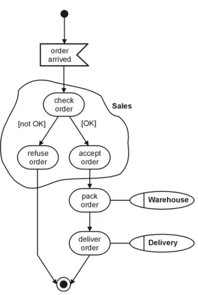
In their original version the event control was introduced as an additional (non-native UML) artefact. In more recent versions of UML the Activity Diagrams are equipped with a feature that allows for sending and receiving signals. Signals come close to what the concept of an event entails in typical business process languages such as the Event-driven Process Chain. But there is one notable difference: in event-oriented business process languages it is often not clear whether an event corresponds to the sending or to the receiving of a signal. Most events do both: they are triggered by an activity and they trigger an(other) activity. The only exceptions are the start and end events which correspond to the receiving and sending of signals, respectively. Figure 1 shows an example of a Business Process Diagram that uses the receiving of the signal “order arrived” as a start event that triggers order processing.
To assign organizational units to activities ‘clouds’ are used (see fig. 1) which have a function similar to that of the swim lanes suggested by (OMG, 2003). In addition BPDs also use a notation borrowed from Event-driven Process Chains (EPCs), an ellipse with a vertical bar, that can be attached to singular activities (see also fig. 1). A similar notation can be employed for the assignment of data containers / objects.
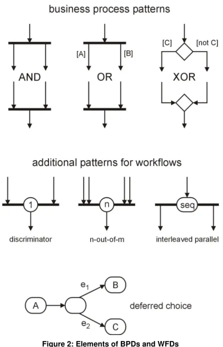
With regard to control flow most business process languages use three elementary concepts: AND, OR and XOR. They are shown in the upper half of figure 2 in the next section. The AND refers to the parallel execution of two or more threads. It corresponds to the fork/join in UML Activity Diagrams as represented by the synchronization bar.
Figure 1: Business Process Diagram
The OR allows for the execution of one or more alternatives out of a set of n alternatives. The matching join waits until all the paths, which have actually been started, are finished. It corresponds to a conditional fork (OMG, 2003, p. 3-169). In the example in figure 2: if condition “A” holds, the left path is taken. If condition “B” holds, the right path is taken. If both conditions hold, both paths are taken. The latter situation is forbidden in the XOR. It should be noted that the definition of the OR join refers to the corresponding fork. This so-called non-local semantics makes it difficult to arrive at a precise, formal description of the OR join’s behaviour. UML tries to avoid this (general) problem by demanding that an Activity Diagram containing conditional forks must be well-structured which means that all problematic situations are simply forbidden. For business process modeling this restriction is considered to be inadmissible. For a discussion of the principal problem in the context of EPCs see (Aalst, Desel, & Kindler, 2002). Constructive approaches to dealing with this problem (also in the context of EPCs) can be found in (Langner et al., 1998), (Dehnert, & Rittgen, 2001) and (Rittgen, 2001).
Finally, the XOR branch demands that exactly one of the outgoing paths is taken. In the example in figure 2: If condition “C” holds, the left path is taken, otherwise the right path. Please observe that the conditions governing the outgoing paths of an XOR must be mutually
ACTIVITY DIAGRAMS AND WORKFLOWS
The market of workflow management systems provides a large number of different products such as COSA, FLOWer, Domino Workflow, Eastman, Visual Workflow, Forté Conductor, Meteor, Mobile, MQSeries/Workflow, Staffware, Verve Workflow, I-Flow, InConcert, Changengine, and SAP R/3 Workflow. A comparative study of these prodcuts with respect to their expressive power has been conducted by (Aalst, Hofstede, Kiepuszewski, & Barros, 2002). The results of this study showed that many of the workflow-specific patterns are not directly supported by most of the products. In addition, most of these approaches define their own workflow language. On the other hand, there are also efforts to standardize the workflow language, most notably XPDL (Workflow Management Coalition, 2002) and BPML (Arkin, 2002). But even these approaches are not complete with respect to the set of workflow patters identified by (Aalst, Hofstede, Kiepuszewski, & Barros, 2002).
In this situation some researchers have tried to develop approaches that 1) support all patterns that are relevant for workflow modeling, and 2) are integrated within a larger standardization effort, in particular UML.
In this context the Activity Diagrams have received considerable attention. Approaches to the use of these diagrams for workflow modeling have been suggested by (Dumas, & Hofstede, 2001) and (Bastos, & Ruiz, 2002) among others. The former have translated the workflow patterns identified in (Aalst, Hofstede, Kiepuszewski, & Barros, 2002) to corresponding patterns in Activity Diagrams. The results show that all patterns can be expressed in this language but many of the elementary workflow patterns, such as discriminator and interleaved parallel routing, translate into complex constructs in the UML world that are too cumbersome to be usable in real-life workflow modeling. We therefore suggest to introduce a few new notational elements for these patterns to extend Activity Diagrams to WorkFlow Diagrams. These new elements are shown in the lower half of figure 2.
They can be seen as “macros” that abbreviate the respective Activity-Diagram constructs shown in (Dumas, & Hofstede, 2001). In this way we can define the precise behaviour of these new elements by recurring to their definition in (Dumas, & Hofstede, 2001) which in turn is rooted in the semantics of Activity Diagrams. Although the latter is not given formally in the UML documentation, there are considerable efforts of the pUML group (precise UML) to provide a mathematically founded semantics for e.g. Activity Diagrams. One of the most advanced approaches aiming in this direction is provided by (Eshuis, 2002). The discriminator is a pattern to express the following situation: you have started two or more parallel threads but you are only interested in the results of the thread that finishes first. All others are ignored. Therefore you do not wait for the others to be finished but proceed immediately after the first result becomes available. As a symbol for the discriminator we suggest a synchronization bar that has a circle in the middle in which the number “1” is inscribed (meaning one result is enough). An example for such a pattern is given in the next section.
Figure 2: Elements of BPDs and WFDs
The n-out-of-m join is a straightforward generalization of the discriminator to the case that more than one result is required. Please observe that m must be greater than n so the simplest case of such a pattern is the 2-out-of-3 join which means that out of three parallel threads you are only interested in the results of the two that finish first and you ignore the one that comes last. The notation for this type of join matches that of the discriminator with the “1” being replaced by the number “n” (“2” in the example). An example of this pattern is a paper that has to be sent to three external reviewers. To speed up the publication process we have determined that the results of two reviews are sufficient to decide on the further processing of the paper (acceptance/rejection). So as soon as the second review is sent in we start the further processing of the paper and we ignore the final review.
The interleaved parallel routing is used when a number of activities has to be performed in an arbitrary sequential order. One can also say that these activities are concurrent but may
in any order (e.g. depending on the availability of lab staff and/or instruments). All of the test have to be performed before the doctor can make the diagnosis.
The deferred choice can be seen as an external (or implicit) choice as opposed to the XOR which represents an internal (or explicit) choice. The difference is that in the case of the internal choice the decision about the path to take is made by the process/workflow itself whereas the external choice involves waiting for events triggered by the environment (e.g. other business processes or workflows or something happening outside the workflow system). The fact that the workflow has to wait gave rise to the name “deferred choice”. So the choice is deferred (delayed) until the respective event occurs. The deferred choice does not require a new notational element as it is already supported by Activity Diagrams if we allow that an activity state is not associated with an activity (or associated with an empty activity). The outgoing arcs of this state must be associated with events. The resulting empty state is a wait state that can only be left when one of the events occurs (see figure 2, bottom). Such a “blank state” is admissible because it is in accordance with the underlying State Machines which also provide wait states. Let us consider the example of a make-or-buy decision. After having accepted a customer order we can either execute the order ourselves or have a subcontractor do it for us. So we ask the subcontractor for a quote (A) and defer the choice between make and buy until we receive this quote. If the quoted price is below our cost price (event e1) we
buy (B), otherwise (event e2) we make (C).
In addition to these workflow-specific constructs, the modeler can go on using the patterns for general business processes as provided by the Business Process Diagrams (AND, OR, XOR).
EXAMPLE
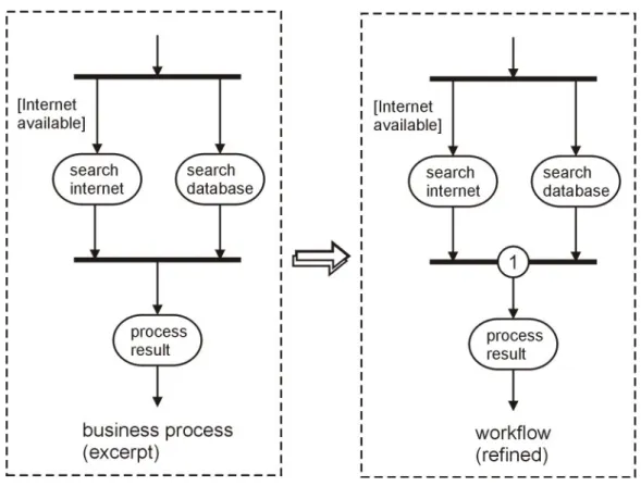
Let us assume that we are in charge of reorganizing the business processes of a company called PicturePro that is concerned with providing photographs to media companies. The customers ask for a picture by describing its content (e.g. We would like to have a photo showing a teenage boy and girl in front of a fountain). Up to now the staff of PicturePro decided on their own how to find an appropriate picture. Some used conventional methods (e.g. filing cabinets), others used individual databases and yet another group used the Internet primarily. Our objective is to make sure that in the future a standardized process is followed by all employees. This process is supposed to be effective and efficient, i.e. a suitable picture must always be found and the effort spent must be within reasonable limits. The CEO of PicturePro also requires that the work is supported by a workflow system to maintain a consistent level of quality, to give the employees better support and to have more flexibility in case of employees being on sick leave or terminating their employment. On the grounds of their lack of efficiency we decide to give up the conventional filing systems. To increase effectiveness we settle on using both the database research and the Internet research for every picture search (see fig. 3).
On the business process level these two parallel paths are joined by a regular OR (the synchronization bar) which would wait for the completion of the internet search (if initiated) even if our local database produces a faster result. That is, of course, inefficient so when we refine the business process into a workflow we decide to use the discriminator instead. Now the processing of the search result will be done as soon as the first result becomes available.
Figure 3: Business Process and Workflow
CONCLUSION
The introduction of UML provided a standard which not only influenced the modeling of software but also that of businesses. Many methods that were so far primarily focused on the business domain are now being equipped with interfaces to UML. On the other hand early versions of the UML paid little attention to business processes and workflows. The use case seemed to be the only UML concept for business modeling and was hence often stretched beyond its original scope, e.g. by employing it to model business processes. Many authors have therefore tried to make use of the powerful UML concept of stereotypes to build application-oriented languages. Contrary to this development the ideas outlined here argue that we need more original support for business-oriented concepts in UML rather than having to specify them as an add-on. The reason for this is that the latter makes it much more difficult to establish a standard for the ‘business add-ons’ and to integrate the business models into the UML world. We have taken another step in this direction by adding the concept of workflows to UML. Others will have to follow to make UML a truly unified language for all aspects of developing information systems.
REFERENCES
Aalst, W.M.P. van der, Desel, J., & Kindler, E. (2002). On the Semantics of EPCs: A Vicious Circle. In M. Nüttgens and F.J. Rump (Eds.). Proceedings of the EPK 2002: Business Process Management using EPCs, Trier, Germany, November 2002. Bonn: Gesell-schaft für Informatik, pp. 71-80,
Arkin, A. (2002). Business Process Modeling Language. November 2002. Aurora, CO: BPMI.org.
Barros, A., Duddy, K., Lawley, M., Milosevic, Z., Raymond, K., & Wood, A. (2000). Processes, Roles, and Events: UML Concepts for Enterprise Architecture. In A. Evans, S. Kent, & B. Selic (Eds.). UML 2000 - The Unified Modeling Language. Advancing the Standard. Third International Conference, York, UK, October 2000. Proceedings. Lecture Notes in Computer Science 1939, Berlin: Springer, pp. 62-77.
Bastos, R. M., & Ruiz, D. D. A. (2002): Extending UML Activity Diagram for Workflow Modeling in Production Systems. In: 35th Hawaii International Conference on System Sciences – 2002, Big Island, Hawaii, January 7 - 10, 2002. Proceedings, vol. 9. Los Alamitos, California: IEEE Computer Society, p. 291
Dehnert, J., & Rittgen, P. (2001). Relaxed Soundness of Business Processes. In K.R.Dittrich, A. Geppert, & M.C. Norrie (Eds.). Advanced Information Systems Engineering, 13th International Conference, CAiSE 2001, Interlaken, Switzerland, June 4-8, 2001. Proceedings. Lecture Notes in Computer Science 2068, Berlin: Springer, pp. 157-170. Dumas, M., Hofstede, A.H.M. ter (2001): UML activity diagrams as a workflow specification
language. In: M. Gogolla and C. Kobryn, editors, Proc. of the 4th Int. Conference on the Unified Modeling Language (UML01), volume 2185 of LNCS, pages 76-90, Toronto, Canada, October 2001. Berlin: Springer.
Eshuis, R. (2002): Semantics and Verification of UML Activity Diagrams for Workflow Modelling. Ph.D. thesis, University of Twente.
Langner, P., Schneider, C., & Wehler, J. (1998). Petri Net Based Certification of Event driven Process Chains. In J. Desel and M. Silva, editors, Application and Theory of Petri Nets, volume 1420 of Lecture Notes in Computer Science. Berlin: Springer, pp. 286– 305.
Nüttgens, M., Feld, T., & Zimmermann, V. (1998). Business Process Modeling with EPC and UML: Transformation or Integration? In M. Schader, & A. Korthaus (Eds.). The Unified Modeling Language - Technical Aspects and Applications. Heidelberg: Springer, pp. 250-261.
OMG (Ed.) (2003). Unified Modeling Language Specification: Version 1.5, March 2003. Needham: OMG.
Ould, M. (1995). Business processes: modeling and analysis for re-engineering and improvement. Chichester: John Wiley and Sons.
Rittgen, P. (2001). E-Commerce Software: From Analysis to Design. In A. Gangopadhyay (Ed.). Managing Business with Electronic Commerce: Issues and Trends. Hershey: Idea Group, pp. 17-36.
Rittgen, P. (2003). Business Processes in UML, in Favre, Liliana: UML and the Unified Process, Hershey, PA: IRM Press, 2003, pp. 315 – 331
Scheer, A.-W. (1999). ARIS - Business Process Modeling. (2 ed.). Berlin: Springer.
Simons, A. J. H., & Graham, I. (1999). 30 Things that go wrong in object modelling with UML 1.3. In H. Kilov, B. Rumpe, I. Simmonds (Eds.). Behavioral Specifications of Businesses and Systems, chapter 17. Amsterdam: Kluwer Academic Publishers, pp. 237-257.
Workflow Management Coalition (2002). Workflow Process Definition Interface -- XML Process Definition Language. Document Number WFMC-TC-1025. Lighthouse Point, FL: Workflow Management Coalition, October 2002.