CHAPTER 10
ULTIMATE LIMIT STATES DESIGN
Article 41. Equilibrium Limit State
It should be verified that the equilibrium limits (overturning, sliding, etc.), are not exceeded under the least favourable loading hypothesis, applying the Rational Mechanical Methods, and taking account of the actual conditions of the supports.
E d,estab ≥ E
in which:
d,desestab
E d,estab
E
The effects of stabilising actions design value.
d,desestab
Article 42. Limit State at Failure under normal stresses
The effects of destabilising actions design value.
42.1 General design principles
42.1.1 Definition of the section
42.1.1.1 Dimensions of the section
In order to obtain strength capacity of a section, this shall be considered using its actual dimensions during the construction or service stage analysed, apart from in the case of T-beams, I-beams or similar members, when the actual widths indicated in 18.2.1 shall be taken into consideration.
42.1.1.2 Resistant section
For the purposes of the calculations for Limit State at Failure under normal stresses, the resistant section of concrete shall be obtained from the dimensions of the member and in compliance with the criteria in 40.3.5.
42.1.2 Basic hypotheses
The design of the ultimate strength capacity of sections shall be conducted on the basis of the following general hypothesis:
a) Failure is characterized by the value of strain in specified fibres of the section, defined by the failure deformation envelopes detailed in 42.1.3.
b) Strain in concrete follows a plane law. This hypothesis is valid for members in which the ratio between the distance between points of zero moment and the total depth is more than 2.
c) The strain εs
The total strain in the active stress in bonded active reinforcements shall take account, not only of the strain that occurs in the corresponding fibre in the plane of strain at failure (ε
in passive reinforcements remains equal to that of the concrete surrounding them.
pre-stressing and the strain of decompression (figure 42.1.2) as defined below: ∆εp = εcp + εp0
in which:
εcp Strain of decompression in the concrete at the level of the fibre in the
reinforcement concerned
εp0 Pre-deformation of the active reinforcement due to pre-stressing action .
during the stage concerned, taking account of any losses that have occurred.
d) The stress-strain design diagram for the concrete shall be any of those defined in 39.5. The tensile strength of the concrete shall be disregarded. The design stress-strain diagram for the steel for passive reinforcements shall be as defined in 38.4. The design stress-strain diagram for steel of active reinforcements shall be as defined in 38.7.
e) The general equations of balanced forces and moments shall be applied to the stresses in the section. This is how the ultimate strength can be calculated by integrating the stresses in the concrete and in the active and passive reinforcements.
Figure 42.1.2
42.1.3 Strain envelopes
The limit stains in sections, depending on the type of stress, enable the following domains to be recognised (figure 42.1.3):
Domain 1: Pure or combined tension where the entire section is under tension. The strain lines turn about point A corresponding to an elongation in the reinforcement of the most tensioned of 10 per 1000.
Domain 2: Pure or combined bending, in which the concrete does not reach the ultimate bending strain. The strain lines turn about point A. Domain 3: Pure or combined bending, in which the strain lines turn about point
B corresponding to the ultimate bending strain of the concrete εcu
defined in paragraph 39.5. The elongation of the most tensioned reinforcement is between 0.01 and εy with εy
Range 4: Single or combined bending in which the strain lines turn around point B. The elongation of the most tensioned reinforcement is between ε
the elongation corresponding to the yield stress of the steel.
y
Range 4a: Combined bending in which all the reinforcements are compressed and where there is a small area of concrete in tension. The strain lines turn about point B.
and 0.
Range 5: Single or combined compression in which both materials are in compression. The strain lines turn about point C, as defined by the line corresponding to the ultimate compression strain of concrete, εc0,
Figure 42.1.3
42.1.4 Design and verification of sections
Based on the basic hypotheses defined in 42.1.2, the equilibrium equations for the section can be established, producing a system of non-linear equations.
When design, the form and dimensions of the concrete section, the position of the reinforcement, the materials’ characteristics and the design stresses are known but the plane of strain at failure and the reinforcement ratio are unknown.
When verifying, the shape and dimensions of the concrete section, the position and of the reinforcement and its ratio, and the materials’ characteristics are known, and the plane of strain at failure and the sectional stresses are unknown.
42.2 Special cases
42.2.1 Minimum eccentricity
On supports and elements performing a similar function, every section submitted to an external normal compression stress Nd
h/20 and 2 cm
shall be capable of withstanding this compression, with a minimum eccentricity, due to the uncertainty at the position of the point of application of the normal stress, equal to the greater of the following values:
This eccentricity shall be calculated starting from the centre of gravity of the gross section, and in the least favourable of the main directions and in only one direction.
42.2.2 The effect of confined concrete
Concrete confined in compression improves its strength and ductility characteristics; the latter being very important for ensuring structural performance, that permits optimum use of all the additional strength capacity of a statically indeterminate element.
Confinement of the compressed zone of concrete can be achieved with a suitable amount of transverse reinforcement that is appropriately arranged and anchored in accordance with the provisions in sub-paragraph 40.3.4.
42.2.3 Unbonded active reinforcements
The increase in tension in non-bonded active reinforcements, depends on the increase in length in the tendon between anchorages which, in their turn, depend on the overall deformation of the structure at Ultimate Limit State.
42.3 Provisions relating to reinforcements
42.3.1 GeneralIn order for any passive reinforcements under compression to be taken into account during design, it will be necessary for them to be secured using hoops or stirrups, whose distance st
apart and diameter φt
s
are as follows:
t 15 φmin (φmin diameter of the thinnest compressed bar)
φt ≥ ¼ φmax (φmax diameter of the thickest compressed bar)
st
Longitudinal passive resistant reinforcement, and skin reinforcement, shall be suitably distributed in order to avoid leaving concrete areas without any reinforcements, so that the distance between two consecutive longitudinal bars (s) satisfies the following limitations:
in compressed members shall always be less than the smaller dimension of the element and not exceed 30 cm.
s ≤ 30 cm.
s ≤ Three times the gross thickness of the part of the member’s section, flanges or webs on which they are going to be located.
In zones where the bars overlap or bend, it may be necessary to increase transverse reinforcement.
42.3.2. Pure or combined bending
Whenever failure in a section occurs due to pure or combined bending, the longitudinal tensile resistant reinforcement shall satisfy the following limitation:
+
+
≥
e
A
W
z
P
f
z
W
f
A
+
d
d
f
A
s yd ctmfl s p pd p 1 , , 1 In which: Ap AArea of the bonded active reinforcement.
s
f
Area of the passive reinforcement.
pd
f
Design value of the tensile strength of bonded active reinforcement steel.
yd
f
Design value of the tensile strength of passive reinforcement steel.
ct,m,fl
W
Average flexural strength of the concrete.
1
d
Section modulus of the gross section relating to the fibre under greatest tension.
p
d
Depth of the active reinforcement from the most compressed fibre in the section.
s
P Pre-stressing force with instantaneous losses disregarded.
Depth of the passive reinforcement from the most compressed fibre in the section.
A Gross concrete section area.
e Eccentricity of the pre-stressing relative to the centre of gravity of the gross section.
z Mechanical lever arm of the section. In the absence of more accurate calculations, this may be taken to be z = 0.8 h.
If there is only active reinforcement in the design section, the following
=
1
s pd
d
shall be considered in the expression above.
In the case of end beam supports, apart from in one-way slabs comprising pre-cast elements, at least one third of the reinforcement necessary to withstand the maximum positive moment shall be continued as far as the supports; this shall be at least a quarter in intermediate beam supports. This reinforcement shall be extended from the centre line of the support by an amount which is the same as the net anchorage length (sub-paragraph 69.5.1).
The lower longitudinal reinforcement in slabs comprising reinforced joists shall comprise at least two bars.
42.3.3 Pure or combined compression
In sections subjected to pure or combined compression, the main reinforcements in compression, A's1and A's2
A '
(see figure 42.3.3) shall satisfy the following limitations:
s1 fyc,d≥ 0.05 Nd A's1 fyc,d≤ 0.5 fcd A A' c s2 fyc,d≥0.05 Nd A's2 fyc,d≤ 0.5 fcd A In which: c
fyc,d Design strength of the steel in compression fyc,d = fyd > 400 N/mm2
N
.
d
f
Factored normal acting compression force
cd
A
Design value of concrete compressive strength.
c Area of the total concrete section.
Figure 42.3.3
42.3.4 Pure or combined tension
In the case of concrete sections subjected to pure or combined tension, containing two main reinforcements, the following limitations shall be satisfied:
Ap f pd + As fyd ≥ P + Ac fct,m
in which P is the pre-stressing force with instantaneous losses disregarded.
42.3.5 Minimum amount of reinforcement (geometric ratios)
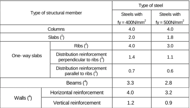
Table 42.3.5 shows the values of the minimum geometric ratios which shall always be provided in the various types of structural elements, depending on the steel used, and provided that these values are more stringent than those indicated in 42.3.2, 42.3.3 and 42.3.4.
Table 42.3.5. Minimum geometric ratios as so many per 1,000, with reference to the total concrete section
Type of structural member
Type of steel Steels with fy = 400N/mm2 Steels with fy = 500N/mm2 Columns 4.0 4.0 Slabs (1) 2.0 1.8
One- way slabs
Ribs (2) 4.0 3.0 Distribution reinforcement perpendicular to ribs (3) 1.4 1.1 Distribution reinforcement parallel to ribs (3) 0.7 0.6 Beams (4) 3.3 2.8 Walls (4) Horizontal reinforcement 4.0 3.2 Vertical reinforcement 1.2 0.9
(1) Minimum ratio of each of longitudinal and transverse reinforcements distributed along both sides. In
the case of foundation slabs and footings, half of these values shall be used in each direction and arranged on the lower side.
(2) Minimum ratio with reference to a rectangular section of width bw
(3) Minimum ratio with reference to the thickness of the in situ concrete compression layer.
and a slab depth in accordance with figure 42.3.5. This ratio shall be strictly applied in ribs but not in solid areas. All joists shall have at least two longitudinal active or passive reinforcements, on their bottom flanges, symmetrical about the middle vertical plane.
(4) Minimum ratio corresponding to the side under tension. It is recommended that a minimum
reinforcement of 30% of the nominal reinforcement is arranged on the opposite side.
(5) The minimum vertical ratio is the ratio corresponding to the side under tension. It is recommended that
a minimum reinforcement of 30% of the nominal reinforcement is arranged on the opposite side. Starting from a height of 2.5 m above the toe of the wall and provided that this distance is not less than half the wall height, the horizontal ratio may be reduced to 2%. If vertical contraction joints are incorporated that are 7.5 m or less apart, with the horizontal reinforcement interrupted, the minimum horizontal geometric ratios may be reduced to 2%. The minimum horizontal reinforcement shall be distributed on both sides. If both the wall’s sides are visible, 50% shall be arranged on each side. In walls more than 50 cm thick, an effective area of maximum thickness 50 cm, with 25 cm distributed on each side, shall be considered, and the central area between these surface layers disregarded.
Figure 42.3.5 Rib detail.
Article 43. Instability Limit State
43.1 General
43.1.1 Definitions
For the purposes of the application of this Article 43, the following terms are used:
- Non-sway structures are structures whose nodes under design actions exhibit
transverse displacement whose effects can be disregarded from the stability point of view of the assembly.
- Sway structures are structures whose nodes at design actions exhibit transverse
displacement whose effects cannot be disregarded from the stability point of view of the assembly
- Isolated supports are statically determined supports, or supports in frameswhere the
position of the points where the second-order moment is zero does not vary with the load size..
- Mechanical slenderness of a constant section support is the quotient of theeffective buckling length l0 of the support (distance between points of inflection of the column’s
deformed shape) divided by the radius of gyration i of the entire concrete section in the direction under consideration.
- Geometric slenderness of a constant section support is the quotient of the effective
buckling length l0 of the support divided by the dimension (b or h) of the section which
is parallel to the plane of buckling.
Frame structures fitted with walls or wind-bracing cores and configured so that they guarantee the structure’s torsional stiffness and which comply with the following, may clearly be considered as non-sway structures.
2 1
6
,
1
h
EI
n
n
k
N
d∑
+
≤
in which: Nd n Number of storeys.Factored vertical load which reaches the foundation with the structure fully loaded.
h Total height of the structure from the upper foundation face.
ΣEl Sum of flexion rigidities of the counter-wind elements in the direction concerned, using the inertia of the gross section for the calculation of l.
ki
43.1.2 Scope
Value constant 0.62. This constant shall be reduced to 0.31 if the bracing elements cracked at Ultimate Limit State.
This Article relates to the verification of isolated supports and frame structures in general, in which the second order effects cannot be disregarded.
The application of this Article is limited to cases in which the effects of torsion can be disregarded.
This Code does not cover cases where the mechanical slenderness of the supports exceeds 200.
The second order effects may be disregarded in insulated supports if their mechanical slenderness is less than a limit slenderness associated with a loss of load bearing capacity in the support of 10%, with respect to a non-slender support. The lower slenderness limit λinf can
100
1
-e
3,4
/
24
,
0
1
5
3
2 2 1 2 inf
>/
+
+
=
e
h
e
C
ν
λ
In which:ν Design value of the on-dimensional or reduced axial force actuating in the support. ν = Nd/(Ac fcd e ) 2 e
First order eccentricity in the end of the support with the larger moment,
deemed to be positive.
1 First order eccentricity at the end of the support with the lower moment which
is positive if it has the same sign as e2
In sway structures, e
.
1/e2
h Depth of the section in the bending plane considered. shall be taken to be equal to 1.0
C Coefficient which depends on the configuration of reinforcements whose values are:
0.24 for symmetrical reinforcement on two opposing sides in the bending plane.
0.20 for equal reinforcement on the four sides
0.16 for symmetrical reinforcement on the lateral sides.
43.2 General method
The general verification of a structure, bearing in mind geometric and mechanical non-linearities can be undertaken in accordance with the general principles indicated in 19.2. This verification justifies the fact that the structure for the various combinations of possible actions, the structure does not present any global or local instability in its constituent members, and that the strength capacity of the various sections of those elements is not exceeded.
The design shall take account of the uncertainties associated with predicting second order effects and, in particular, dimension errors and uncertainties in the position and line of action of the axial loads.
43.3 Verification of non-sway structures
The overall forces in non-sway structures may be derived according to first order theory. Based on the forces obtained in this manner, a verification shall be undertaken on the second order effects of each support considered in isolation, in accordance with 43.5.
43.4 Verification of sway structures
Sway structures shall be subject to stability verification in accordance with the general basic principles of 43.2.
For common building structures of less than 15 storeys, in which the maximum displacement at their top at characteristic horizontal loads, calculated using the first order theory and with the stiffness corresponding to gross sections, does not exceed 1/750 of the total height, each support merely needs to be verified in isolation, with the forces obtained by applying the first order theory and the buckling length in accordance with the following:
)
+
(
+
7,5
1,6
+
)
+
(
4
+
7,5
=
B A B A B Aψ
ψ
ψ
ψ
ψ
ψ
α
⋅
In which:ψ Represents the ratio of rigidities
∑
L EI of the supports at
∑
L EI of the beams at each end A and B of the support considered. The gross inertia of the sectionshall be used as the value of I.
α is the buckling length factor which shall take the following values as
appropriate:
Double-fixed-end support (lo
Double-pinned support (l
= 0.5 l)
o
Fixed-end and pinned support (l
= l)
o
Cantilever support (l
=0.7 l)
o
Double-fixed-end support with moveable ends. (l = 2 l)
o
43.5 Verification of isolated supports
= l)
The approximate method of 43.5.1 or 43.5.2 may be used with supports with a mechanical slenderness of between λinf
The approximate method of 43.2 may be used with supports with a mechanical slenderness of between 100 and 200.
and 100.
43.5.1 Approximate method. Straight combined bending
The cross-section for supports with constant section and reinforcement shall be dimensioned for a total eccentricity of:
e
e
+
e
=
e
tot e a≥
2(
)
(
)
i
50
l
e
10
+
h
e
20
+
h
+
=
e
c 2 0 e e y a1
+
0
,
12
β
ε
0
,
0035
in which: ea eFictitious eccentricity used to represent the second order effects.
e
e
Equivalent first order design eccentricity.
e= 0.6e2 + 0.4e1≥ 0.4e2
e
for non-sway supports;
e = e2
e
for sway supports.
1, e2
l
Eccentricities of axial force at the ends of the member defined in 43.1.2.
0
i
Buckling length.
c
h Total depth of the concrete section.
Radius of gyration of the concrete section in the direction concerned. εy Deformation in the steel for the design stress fyd
ε , i.e., y 3
E
f
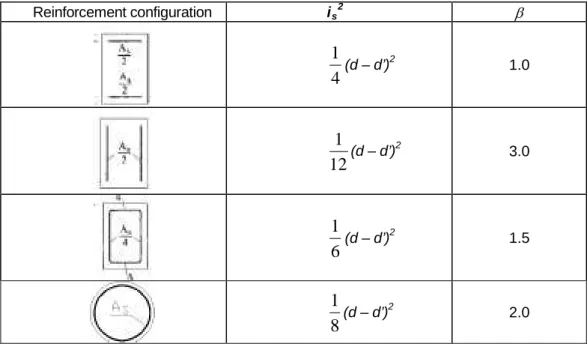
yd =β Reinforcement factor obtained from
i
4
)
d
-(d
=
2 s 2′
β
with isbeing the radius of gyration of the reinforcements. The values of β and is are
Table 43.5.1 Reinforcement configuration is 2 β 4 1 (d – d’)2 1.0 12 1 (d – d’)2 3.0 6 1 (d – d’)2 1.5
8
1
(d – d’)2 2.043.5.2 Approximate method. Biaxial combined bending
A separate verification may be carried out on rectangular cross-section elements constant reinforcement, along the two main planes of symmetry if the eccentricity of the axial load is located in the shaded area in figure 43.5.2.a. This situation obtains if any of the two conditions set out in figure 43.5.2.a, are satisfied, in which ex and ey
If the conditions above are not satisfied, the support shall be deemed to be buckle-resistant, if it satisfies the following condition:
are the design eccentricities in the direction of the x and y axes respectively.
1
M
M
+
M
M
yu yd xu xd≤
In which: Mxd Mis the design moment in direction x, in the critical verification section, taking account of the second order effects.
yd
M
is the design moment in direction y, in the critical verification section, taking account of the second order effects.
xu
M
is the maximum moment in direction x, resisted by the critical section.
yu is the maximum moment in direction y, resisted by the critical section.
Article 44. Limit State of Failure due to shear
44.1 General considerations
When analysing the bearing capacity of concrete structures with regards to shear stresses, the general design strut-and-tie method (Articles 24 and 40) shall be used on all structural members or their parts which have planes states of stress, or similar, and which are subjected to shear actions along a known plane and which are not special cases explicitly covered by this Code, such as linear members, plates, slabs, including one-way slabs and similar structures (44.2).
44.2 Shear strength of linear members, plates, and slabs, including one-way
slabs and similar structures
The requirements in the various sub paragraphs shall solely apply to linear members subjected to combined bending, shear and axial forces (in compression or tension) and to plates, slabs including basically one-way slabs.
For the purposes of this article, linear members shall be members whose distance between points of zero moment is at least twice their total depth, and whose width is no more than five times this depth, and with their main axes being straight or curved. Flat surface elements with a solid or hollow sections loaded perpendicular to their centre plane are called plates or slabs.
44.2.1 Definition of design section
For design at the Limit State of Failure due to shear stresses, sections should be
considered with their actual dimensions during the phase being analysed. Except where indicated otherwise, the resistant concrete section is obtained from the actual dimensions of the member, with the criteria of 40.3.5 being met.
If the web width in the section considered is not constant, the smallest width in the section at a height equal to three quarters of the effective depth calculated from the tensioning reinforcement (figure 44.2.1.a) shall be adopted for b0
Figure 44.2.1.a
.
44.2.2 Effective shear force
Verifications at the Limit State of Failure due to shear may be carried out based on the effective shear stress Vrd obtained from the following expression:
Vrd = V d+ Vpd+ V
in which:
cd
Vd
V
Design value of the shear force produced by external actions.
pd
V
Design value of the force component of the pre-stressing tendons parallel to the section under study.
cd Design value of the component parallel to the section of the resultant normal tensions,
both compression and traction the passive reinforcement, on the longitudinal concrete fibres, in members with variable depth.
44.2.3 Compulsory verifications
The Limit State of Failure due to shear will be reached when either the compressive strength of the web or its tensile strength is exhausted. It is consequently necessary to verify that both the following conditions are simultaneously satisfied
V
V
rd≤
u1V
V
rd≤
u2 in which: Vrt VDesign value of the effective shear force in 44.2.2.
u1
V
Ultimate shear force failure due to diagonal compression in the web..
u2 Ultim
Verification of failure due to diagonal compression in the web ate shear force failure due to tension in the web Vrd ≤ Vu1
In members without any shear reinforcement, failure due to diagonal compression will not need to be verified.
shall be conducted at the edge of the support and not at its axis.
Verification of failure due to tension in the web Vrd ≤ V u2
44.2.3.1 Obtaining V
shall be carried out on a section located at a distance of one effective depth from the edge of the direct support., apart from in the case of members without any shear reinforcements in regions which do not crack in flexion, when the provisions in 44.2.3.2.1.a shall apply.
Shear stress at failure due to diagonal compression in the web shall be calculated from the following expression: u1
θ
α
θ
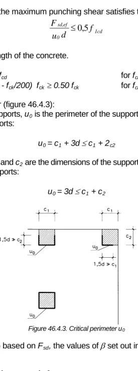
cotg + 1 cotg + cotg d b f K = Vu1 1cd 0 2 in which: f1cd fThe concrete’s compression strength.
lcd = 0.60 f cd for fck
f
≤ 60 N/mm²
lcd = (0.90 - f ck/200) fcd≥ 0.50 fcd for fck > 60 N/mm²
b0
K Coefficient which depends on the axial force.
Net minimum width of the member defined in accordance with
40.3.5.
K = 1.00 In the case of non-pre-stressed structures or structures without any axial compression force.
K = 1 + cd cd
f
'
σ
for 0 < σ’cd ≤ 0.25 f K = 1.25 for 0.25 f cd cd < σ’cd ≤ 0.50 f K = 2.5 cd
−
cd cdf
'
1
σ
for 0.50 fcd < σ’cd ≤ 1.00 f In which: cdσ’cd Effective axial tension in the concrete (positive compression), which in columns
shall be calculated bearing in mind the compression absorbed by the compressed reinforcements.
A
N
=
c ' d cd yd sf
A
−
′
σ
Nd
A
Design value of the axial force (positive compression) including pre-stressing with its design value.
c
A
Total concrete cross section area.
s’ Total area of compressed reinforcement. In combined compression, it may be
assumed that the entire reinforcement is subject to the tension fyd
f
.
yd Design strength of reinforcement As
In the case of passive reinforcements: f
’ (paragraph 40.2).
yd = σ
In the case of active reinforcements: f
sd
yd = σ
α Angle between the reinforcements and the member’s axis (figure 44.2.3.1).
pd
θ Angle between the compression struts in the concrete and the member’s axis (figure 44.2.3.1). A value which satisfies the following shall be adopted:
0.5 ≤ cotg θ ≤ 2.0
Figure 44.2.3.1
44.2.3.2 Obtaining V
44.2.3.2.1 Members without any shear reinforcement
u2
44.2.3.2.1.1 Members without any shear reinforcement in non-cracked regions (Md ≤ Mfis,d)
The shear strength of members with non-cracked regions and compressed webs shall be restricted according to the concrete’s tensile strength, and shall be equal to:
( )
l cd ct,d 2 d , ct 0 2 u f ' f S b I V = ⋅ +α
σ
in which : Md MDesign moment of the section.
fis,d Cracking moment of the section calculated using fct,d = fct,k/γc
I Moment of inertia of the transverse section.
. b0 Width of the web according to sub-paragraph 44.2.1.
S Static moment of the transverse section.
fct.d
σ’
Design value of the concrete’s tensile strength.
cd
α/ Mean compression tension in the concrete due to pre-stressing force. = l/(1.2 /bd) ≤1 in the case of pre-stressing tendons.
l
= 1 in the case of other types of bonded pre-stressing elements.
x
l
Distance in mm of the section concerned from the start of the length of transfer .
bpt
l
Length of transfer of the active pre-stressing reinforcement in mm, which may be adopted according to sub paragraph 70.2.3.
bpt = φ σp / 21 In which: SHEAR REINFORCEMENT COMPRESSION STRUTS
σp
φ Diameter of the active reinforcement in mm. Pre-stressing tension, after losses, in N/mm²
This verification shall be undertaken on a section located a distance away from the edge of the support which corresponds with the intersection of the longitudinal axis passing through the centre of gravity of the section with a line at an angle of 45. starting from the edge of the support.
When determining whether the section in members comprising pre-cast elements and in situ concrete is cracked or not in flexure, (calculation of Mdand Mfis,d
In one-way slabs comprising pre-cast, pre-stressed joists with in situ concrete forming the other ribs and compression flange, webs are not compressed by the pre-stressing of the joists, or in any case, compression is greatly reduced and transmitted over time by creep. The ultimate shear force resisted shall therefore be the larger of the figures obtained on the basis of this article, considering the pre-stressed joists in isolation or using shear verification according to sub-paragraph 44.2.3.2.1.2.
) its various constructional phases shall be taken into consideration; the acting loads and resistant sections shall be taken into consideration at each of these phases and the tensions corresponding to each phase superimposed.
44.2.3.2.1.2 Members without shear reinforcement in regions cracked in flexure (Md > Mfis.d)
Ultimate shear force failure due to tensile force in the web in conventional and high strength concrete members shall be:
(
100 f)
0,15 b d 18 , 0 V 1 cv 1/3 'cd 0 c 2 u σ + ρ ξ γ =With a minimum value of:
d b 15 , 0 f 075 , 0 V 3/2 cv1/2 'cd 0 c 2 u σ + ξ γ = in which :
fCV Effective shear strength of the concrete in N/mm² with a value of fcv =
fck with fcv not more than 15 N/mm² in the case of reduced concrete
control, with fck being the concrete’s compression strength, which, for
the purposes of this paragraph, shall be considered not to exceed 60 N/mm². ξ = 1 200≤2.0 + d with d in mm.
d Effective depth of the cross-section with reference to the longitudinal bending reinforcement, provided that this is capable of withstanding the increase in tensile stress produced by the shear-flexure interaction (see paragraph 44.2.3.4.2). σ’cd MPa 12 f 30 , 0 A N ' cd c d cd= < >/ σ
Mean axial tension in the web of the section (positive compression).
Nd Design value of the axial force including the pre-stressing force present
in the section considered. a linear variation in the pre-stressing force may be considered in members with pre-tensioned reinforcements, from the end of
the member as far as a distance equal to 1.2 times the transfer length lbpt, (see
44.2.3.2.1.1). On internal supports of continuous structural with active passing reinforcement, the contribution of the pre-stressing axial force shall be disregarded when calculating Nd
ρ1 . 0,02 d b A + A = 0 p s l ≤
ρ
Geometric ratio of the main longitudinal tensioning reinforcement, whether, bonded passive or active reinforcement, anchored at least a distance, d, away from the section considered.
In the case of slabs with pre-cast pre-stressed joists, the ultimate shear force failure due to tensile force in the web shall be less than the values obtained by considering on the one hand the minimum width of the pre-stressed rib and, on the other hand, the smallest width of the in situ concrete above the joist, bearing in mind that the resisted shear Vu2
In the first case, the design value of the concrete’s compressive strength shall be deemed to be that of the pre-stressed joist, the tension, σ’
shall be more than the minimum value set out in this article.
cd shall refer to the area of the joist and the
geometric ratio of the reinforcement shall refer to a reference cross-section of width b0 and a
depth d, with b0
In the second case, the compressive strength of the in situ concrete shall be considered to be the concrete’s compressive strength, the tension σ’
being the minimum width of the rib, and d, the effective depth of the slab.
cd shall be deemed to be zero, and the
geometric ratio of the reinforcement shall refer to a cross-section of width b0and a depth d, with
b0
In one-way slabs comprising basic lattice reinforcement, the contribution of the lattice may be considered (in accordance with sub-paragraph 44.2.3.2.2), when verifying the shear force using the smallest width underneath the fibre corresponding to a depth of at least 20 mm below the lattice’s upper round bar, as the rib width. Similarly, the rib shall be verified without the contribution of the lattice, using the rib’s smaller width, between 20 mm below the lattice’s upper round bar and the upper face of the slab (Figure 44.2.1.b).
being the minimum width of the rib in the zone of the in situ cast concrete above the beam.
44.2.3.2.2 Members with shear reinforcement
Ultimate shear force failure due to tensile force in the web shall be equivalent to:
V
+
V
=
V
u2 cu su In which: Vsu VContribution of the web’s transverse reinforcement to shear strength.
su = z sen α ( cotg α + cotg θ )Σ Aa f
In which:
yαd
Aα
f
Area per unit length of each set of reinforcements forming an angle α with the main axis of the member (figure 44.2.3.1)
yα.d Design strength of the reinforcement Aα
In the case of passive reinforcements: f
(paragraph 40.2).
yd= σ’
In the case of active reinforcements: f
sd
pyd = σ’
θ Angle between the concrete’s compression struts and the axis of the member (figure 44.2.3.1). The same value as that for verifying shear force failure due to diagonal compression in the web (paragraph 44.2.3.1) shall be adopted. It shall satisfy the following:
pd
0.5 ≤ cotg θ ≤ 2.0
α Angle of the reinforcements with the member’s axis (figure 44.2.3.1).
z Mechanic lever arm. In pure bending and in the absence of more accurate calculations, the approximate value of z = 0.9d may be adopted. In the case of in circular sections stressed in flexure, d may be considered to be 0.8 h. In circular sections stressed in flexural compression, z may be approximately:
(
)
>/
>
−
+
−
−
+
=
d
U
U
N
d
d
U
z
N
M
z
s s d s d d9
.
0
0
'
' ' 0 , in which: z0d, d' Distance from the most compressed fibre in the concrete as far as the
centre of gravity of the tensioned and compressed reinforcement respectively.
Distance from the tensioned reinforcement as far as the application point of the axial force.
Us = Asfyd
U’
Mechanical strength of the tensioning reinforcement.
s = A’sfyd Mechanical strength of the compression reinforcement.
For combined flexure and tension, 0.9d may be adopted for z. The value of Vsu
V
in members reinforced with circular hoops, shall be multiplied by a factor of 0.85 to take account of the loss of efficiency of the shear reinforcement due to the transverse inclination of its constituent elements.
cu
d
b
0,15
)
f
100
(
0,1
=
V
l cd 0 3 1/ cv l C cuξ
ρ
α
σ
β
γ
′
+
5
Contribution of the concrete to shear strength,
In which:
fcv Effective shear strength of the concrete in N/mm2 with a value of fcv= fck with fcv not
exceeding 15 N/mm2
f
in the case of reduced concrete inspection.
ck Compression strength of the concrete in N/mm2. Values of fck of up to 100 N/mm2 shall
be adopted. and in which:
1
-cotg
2
1
cotg
2
=
e
θ
θ
β
si 0,5≤ cotgθ <cotg θe2
cotg
2
cotg
=
e
θ
θ
β
si cotg θe θ ≤ cotg θ ≤2,0 e a) Simplified method.θReference angle of inclination of cracks, for which either of the following two values may be adopted:
e is the angle corresponding to the inclination of the cracks
in the web of the member at the time of cracking, calculated from the following expression:
≤
≥
2,0
0,5
-f
+
)
+
(
f
-f
=
cotg
yd m ct, yd xd yd xd m ct, 2 m ct, eσ
σ
σ
σ
σ
θ
fct,mσxdσyd Mean tensile strength of the concrete (paragraph 39.1). Design values of normal tensions at the centre of gravity of the
section parallel to the main axis of the member and at shear stress Vd respectively. The tensions σxd and σyd shall be
obtained from the design actions, including the pre-stressing tensions in accordance with the theory of elasticity and
assuming non-cracked concrete and considering the tensile stresses to be positive.
b) General method. The angle θe in sixtieths of a degree can be obtained by
considering the interaction with other Ultimate Limit States forces, whose value in degrees may be obtained from the following expression:
θe = 29 + 7ε
in which:
x
εx Longitudinal strain in the web (figure 44.2.3.2.2) expressed as so
many per thousand, and obtained using the following equation:
(
)
1000 0 2 5 , 0 0 </ ⋅ + − − + ≈ p p s s p p d rd d x A E A E A N V z Mσ
ε
Figure 44.2.3.2.2σP0 Tension in the pre-stressing tendons, when the surrounding concrete’s
strain is 0.
The following considerations shall be taken into account when calculating the value of the longitudinal strain in the web, εx
a) V
,:
rd and Mdshall be taken as positive, and Mdshall be taken to be not less than z-Vrd
b) N
.
d
c) The values of A
shall be deemed to be positive compression.
s and Ap
d) If tensile stress can produce cracking in the compressed flange, the value of ε are those of the reinforcement anchored in the section considered. If this is not the case, it shall be reduced in proportion to its anchorage length shortfall.
x
44.2.3.3 Special load cases
obtained in the equation shall be doubled.
When a beam is subjected to a hanging load applied at a level whereby it lies outside the compression flange of the beam, suitable transverse reinforcement and suspension reinforcement shall be arranged and suitable anchored in order to transfer the corresponding load to the compression flange.
Additionally, the end zones of pre-stressed members, especially in case of pre-tensioned active reinforcements anchored by bonding, it will be necessary to examine the progressive transfer of the pre-stressing force to the member, by assessing this force in each section..
44.2.3.4 Arrangements for reinforcements
44.2.3.4.1 Transverse reinforcements
The longitudinal distance st
s
between transverse reinforcements (figure 44.2.3.1) shall satisfy the following conditions, in order to ensure suitable confinement of the concrete subjected to diagonal compression: t≤ 0.75 d (1+cotgα) ≤ 600 mm if Vrd
5
1
≤ V s ul t 5 1 ≤0.60 d (1+cotgα) ≤ 450 mm if Vul < Vrd 3 2 ≤ V s ul t≤0.30 d (1+cotgα) ≤ 300 mm if Vrd 3 2 > VIn bent bars this spacing shall never exceed the value of 0.6 d (1+cotα). The transverse spacing s
ul
t,trans
s
between transverse reinforcements shall satisfy the following condition:
t,trans
If there is compression reinforcement present and this is taken into consideration in the calculation, hoops or stirrups shall also satisfy the requirements in Article 42.
≤d≤500 mm
In general, the linear elements shall include cross-sectional reinforcement in an effective manner.
Hoops and stirrups shall also be extended for a length that is equal to half the depth of the member beyond the section in which they theoretically cease to be necessary. Hoops and stirrups in supports shall be arranged close to their edges.
Shear reinforcements shall form an angle with the axis of the beam of between 45. and 90., sloping in the same direction as the main tensile stress produced by external loads at the centre of gravity of the section of the beam which is assumed to be not cracked.
Bars forming transverse reinforcement may be active or passive and both types can be arranged in an isolated or combined manner. Their minimum reinforcement ratio shall satisfy the following:
b
f
sen
f
A
0 m ct d , y5
,
7
,≥
∑
α
α αAt least one third of the shear reinforcement necessary and in every case, the minimum ratio indicated shall be installed in the form of stirrups forming an angle of 90. with the centre line of the beam. However, in ribbed one-way slabs with a depth not exceeding 40 cm, basic lattice reinforcements may be used for the shear reinforcement whenever a prefabricated footing is used or if the rib is completely concreted in situ.
44.2.3.4.2 Longitudinal reinforcements
The longitudinal reinforcements for bending shall be capable of withstanding an increase in tension on top of that produced by Md, of:
) cotg + cotg ( 2 V -cotg V = T su rd
θ
θ
α
∆This specification is automatically met if the curve of design moments Md is offset by an
amount equal to:
)
cotg
+
cotg
(
V
V
2
1
-cotg
z
=
s
rd su dθ
θ
α
OFFSET LAW in the least favourable direction. (figure 44.2.3.4.2).
If no shear reinforcement is present, Vsu
Figure 44.2.3.4.2
shall be taken to be 0 in the expressions above.
44.2.3.5 Longitudinal shear between the flanges and web of a beam
The strut and ties method shall be used to calculate the reinforcement connecting the flanges and the web of T-beams, I-beams and box girders and similar, (Article 40).
When determining the longitudinal shear force plastic redistribution may be assumed in a beam area of length ar(figure 44.2.3.5.a).
Figure 44.2.3.5.a
The mean longitudinal shear force per unit length which must be resisted shall be:
a
F
=
S
r d d∆
in which:ar Length of plastic redistribution concerned. The law of moments in the length, ar shall
exhibit a monotonously increasing or decreasing variation. At least the points of moment sign change shall always be adopted as zone ar
∆F
limits.
d Variation in the distance ar
In the absence of more rigorous calculations, the following shall be satisfied:
of the longitudinal shear force acting on the section of the flange outside the plane P.
Sd≤Su1
Sd≤ S
In which:
u2
Su1
S
Ultimate longitudinal shear force due to diagonal compression in the plane P.
u1 = 0.5 f 1cd h
In which:
0
f 1cd The
- In the case of compressed flanges:
concrete’s compression strength (sub-paragraph 40.3.2) with a value of:
f1cd = 0.60 fcd for fck
f
≤ 60 N/mm²
1cd = (0.90fck/200)fcd for fck > 60 N/mm²
- In the case of tensioned flanges:
f1cd = 0.40 fcd
h
in the case of tensioned flanges. 0
S
Thickness of the flange in accordance with 40.3.5.
u2
S
Ultimate longitudinal shear force due to tension in plane P.
u2 = S
In which:
su
Ssu
S
Contribution of the reinforcement perpendicular to the plane P to the shear strength.
su = Ap f yp,d
Ap
f
Reinforcement per unit length perpendicular to plane P (figures 44.2.3.5. b and c).
yp,d Design strength of the reinforcement Ap
f
:
yp,d = σsd
f
in the case of passive reinforcements
yp,d = σpd in the case of active reinforcements
Where there is longitudinal shear between flanges and webs, combined with transverse bending, the reinforcements necessary under both headings shall be calculated and the total of these two used; the longitudinal shear reinforcement may be reduced, bearing in mind compression due to transverse bending.
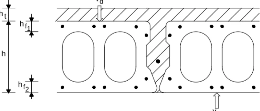
4.4.2.3.6 Vertical shear at joints in hollow core slabs
The vertical shear force per unit length in longitudinal joints in hollow core slabs comprising in situ concrete, Vd, (Figure 44.2.3.6) shall not exceed the resisted shear force Vu, calculated as being the smaller of the following values:
(
⋅
∑
+
⋅
)
=
btd f ctd t uf
h
f
h
V
0
,
25
, ,(
t)
d ct u f h h V =0,15 , +vd h t h h f h 1 2 f d v
Figure 44.2.3.6 Shear force in joints of pre-stressed hollow core slabs
In which:
fbt,d
f
Design tensile strength of the concrete in the precast slab.
ct,d
Σh
Design tensile strength of in situ concrete.
f
h Net height of the joint.
Sum of the smaller thicknesses of the upper and lower flanges of the precast slab
(figure 44.2.3.6).
ht
44.2.3.7 Punching in one way slabs
Thickness of the concrete of in situ cast upper slab.
The slab’s puncture resistance shall be verified if large concentrated loads are to be applied,.
Slabs subjected to large concentrated loads shall be provided with an upper in situ cast slab and subjected to a special study.
The point load on the precast hollow core slab of in pre-cast hollow core slabs without any in situ cast upper slab shall not exceed:
Vd=bwh(fctd+0,3-a-acpm
In which:
)
bw
h Total height of the slab.
Effective width, obtained from the sum of the flanges affected in accordance with
figure 44.2.3.7.
fct,d
σcPm Design tensile strength of the concrete in the precast slab.
α Coefficient equal to [xl(1.2-/
Mean tensile stress in the concrete due to the pre-stressing force.
bpt
In which:
)] ≤ 1.
x Distance from the section to the end.
lbpt Transfer length of the active pre-stressing reinforcement (paragraph 70.2.3).
45 o
bw1 bw2 bw3 bw1 bw2
o
45
a) General situation b) Free slab edge
Figure 44.2.3.7. Effective width in pre-stressed hollow core slabs
In the case of concentrated loads of which more than 50% are acting on a free edge of the slab with a width of bw(see figure 44.2.3.7.b), the strength value obtained from the formula is
transverse passive reinforcement. If either of these two conditions is not satisfied, the strength must be divided by a factor of 2.
Plates or bars shall be fitted in the upper part of the element as the transverse passive reinforcement; they shall be at least 1.20 m long, be fully anchored and designed to resist a tensile force that is equal to the total concentrated load.
If there is a load with a width of less than half the width of the cavity on any cavity, a second strength value shall be calculated using the previous formula, but replacing h with the smaller thickness of the upper flange, and bw with the width of the loaded zone. When verifying, the
smaller of the strength values calculated above shall be adopted.
Article 45 Limit State of Failure due to torsion in linear elements
45.1 General considerations
The requirements in this article shall solely apply to linear elements subjected to pure torsion or the combined stresses of torsion and both shear and axial bending.
For the purposes of this article, linear elements shall be deemed to be elements whose distance between points of zero moment is at least two and a half times their total depth, and whose width is no more than four times that depth with their main axes being straight or curved.
The two-dimensional bending states (mx, my and mxy
When the static equilibrium of a structure depends on the torsional resistance of one or more of its elements, these shall be dimensioned and verified in accordance with this article. When the static equilibrium of the structure does not depend on the torsional resistance strength of one or more of its elements, this limit state will merely need to be verified in elements whose torsional stiffness has been considered in the forces design.
) in slabs and plates shall be dimensioned in accordance with Article 42, taking account of the main directions of the forces and the directions in which the reinforcement is arranged.
45.2 Pure torsion
45.2.1 Definition of the design section
The torsional resistance of sections shall be calculated using a thin walled closed section. This means that solid sections shall be replaced by equivalent thin walled sections. Sections of complex shapes, such as T-beams, shall be divided into several sub-sections, each of which shall be modelled as an equivalent thin walled section, and their total torsional resistance shall be calculated as the sum of the resistances of the various members. Sections shall be divided in order to maximise calculated stiffness. In areas near to supports, their elements whose transmission of stresses to the support elements cannot take place directly shall be not considered as collaborating to the torsional stiffness of the section.
The effective thickness, heof the wall of the design section (figure 45.2.1) shall be:
≥
≤
≤
c
h
u
A
h
e o2
in which:A Area of the transverse section inscribed in the external circumference including
inner void areas.
u External circumference of the transverse section.
ho
c Covering of longitudinal reinforcements.
Actual thickness of the wall in the case of hollow sections.
A value of he less than A/u, may be used provided that it satisfies the minimum conditions
indicated, and so that the concrete compression requirements set out in 45.2.2.1 can be satisfied.
Figure 45.2.1
45.2.2 Verifications that should be performed
The Limit State of Failure due to torsion will be reached when either the compressive strength of the concrete or the tensile strength of the reinforcement arrangement is exhausted.
It is consequently necessary to verify that both the following conditions are simultaneously satisfied: Td ≤ T T u1 d ≤ T T u2 d ≤ T In which: u3 Td T
Design value of the torsional moment for the section.
u1
T
Maximum torsional moment which the concrete’s compressed struts can resist.
u2
T
Maximum torsional moment which transverse reinforcements can resist.
u3 Maximum torsional moment which longitudinal reinforcements can resist.
Torsional reinforcements are assumed to comprise a transverse reinforcement formed from continuous hoops, located in planes perpendicular to the member’s main axis. Longitudinal reinforcements shall comprise passive or active reinforcement parallel to the member’s main axis, distributed uniformly and not more than 30 cm apart on the external circumference of the effective hollow section or in a double layer in the external circumference and on the inside of the effective or actual hollow section. At least one longitudinal bar shall be located on each corner of the actual section, to ensure the transmission of the longitudinal forces exerted by the compression struts to the transverse reinforcement.
45.2.2.1 Obtaining T
The ultimate torsional force that compressed struts can resist may be obtained from the following expression:
u1
in which:
f1cd
f
Concrete’s compression strength.
1cd = 0.60 fcd for fck
f
≤ 60 N/mm²
1cd = (0.90 - fck/200)fcd≥ 0.50 fcd for fck
K Coefficient which depends on the axial force defined in sub-paragraph 44.2.3.1.
> 60 N/mm²
α 0.60 if there are stirrups only along the external circumference of the member;
0.75 if closed stirrups are installed on both faces of the wall of the equivalent hollow section or the actual hollow section.
COVER LONGITUDINAL REINFORCEMENT MID-LINE PERIMETER U0 AREA A0 PERIMETER U AREA A
θ Angle between the concrete’s compression struts and the member’s axis. The expressions in Article 44 may be used to obtain this angle. A value that is consistent with the value adopted for verifying the Ultimate Limit State of failure due to shear and which satisfies the following shall be adopted:
0.50 ≤cotg θ ≤ 2.00
Ae
45.2.2.2 Obtaining T
Area enclosed by the middle line of the design effective hollow section (figure
45.2.1).
The torsional stress which transverse reinforcements can resist is obtained from: u2
θ
cotg
f
s
A
A
2
=
T
y t,d t t e u2 in which: At sArea of the reinforcements used as hoops or transverse reinforcement.
t
f
Longitudinal spacing between hoops or bars in the transverse
reinforcement.
yt,d Design strength of the reinforcement steel At
- For passive reinforcements: f
(paragraph 40.2).
yt,d = σsd
- For active reinforcements: f
yt,d = σ 45.2.2.3 Obtaining T
pd
The tensional stress which longitudinal reinforcements can resist may be calculated using:
u3
θ
tg
f
A
u
A
2
=
T
l yl,d e e u3 in which: A1 fArea of the longitudinal reinforcements.
y1d Design strength of the steel in the longitudinal reinforcements A1
- For passive reinforcements: f
(paragraph 40.2).
y1,d = σsd
- For active reinforcements: f
y1,d = σ
u
pd
e Circumference of the middle line in the design effective hollow section Ae
45.2.2.4 Warping caused by torsion
(figure 45.2.1).
In general, the stresses produced by the co-action of torsional warping may be disregarded in the design of linear concrete members.
45.2.3 Provisions relating to reinforcements
The longitudinal distance between torsional stirrups stshall not exceed:
8 u
st≤ e
and shall satisfy the following conditions to ensure suitable confinement of the concrete subjected to diagonal compression:
st≤ 0,75 a (1+cotgα) ≤ a
>/
600
mm T 5 1 T si d≤ u1 st≤ 0,60 a (1+cotgα) ≤ a>/
450
mmT
3
2
T
<
T
5
1
si
u1 d≤
u1st≤ 0,30 a (1+cotgα) ≤ a
>/
300
mm T 3 2 > T si d u1with a being the smaller dimension of the sides, making up circumference ue
45.3 Interaction between torsion and other stresses
.
45.3.1 General method
The same procedure as for pure torsion (45.2.1) shall be used, in order to define a design effective hollow section. The perpendicular and tangential stresses produced by the forces acting on this section shall be calculated using the conventional elastic or plastic methods.
Once the tensions have been determined, the reinforcements necessary in any wall in the design effective hollow section may be determined using the plane tension distribution formulae. The main compressive stress in the concrete can also be determined. If the reinforcements obtained from this method are not feasible or appropriate, the tensions obtained in any zone may be replaced by a system of equivalent static forces, and these may be used in the reinforcement. In this case, the consequences that this change has in unusual areas such as hollows or beam ends shall be verified.
The main compressive stresses σcd
f
1cdcd
α
σ
≤
2
calculated in the concrete, in the various walls of the design effective hollow section, shall satisfy:
in which α and f1cd
45.3.2 Simplified methods
are defined in 45.2.2.1. and 40.3, respectively.
45.3.2.1 Torsion combined with bending and axial loads.
The longitudinal reinforcements necessary for torsion and flexural compression or flexural tension shall be calculated separately, assuming that both types of load are acting independently. The reinforcements determined in this way shall be combined in accordance with the following rules:
a) In the area stressed due to combined bending, the longitudinal reinforcements for torsion shall be added to those required for bending and axial stresses. b) In the area compressed due to combined bending, if the tensile stress
generated solely by the torsional force is greater than the compressive force acting on that area due to combined bending, a longitudinal reinforcement capable of resisting this difference shall be incorporated. If this is not the case, it shall be verified whether it is necessary to incorporate a compressed longitudinal reinforcement, whose ratio may be determined using the following expression:
0
25
.
0
5
.
0
2≥
⋅
−
+
⋅
⋅
−
=
⋅
cd cd md yd lf
f
f
α
τ
α
σ
ρ
In which: pL e s Lh
s
A
'∆
=
ρ
Ratio of longitudinal reinforcement per unit length to be added in the compression zone of the effective hollow section due to the effect of the torsional moment.
σmd Mean compression tension in the concrete present in the
compressed zone of the effective hollow section due to the design bending and axial forces (Md, Nd) acting concomitantly with the design
torsional stress (Td
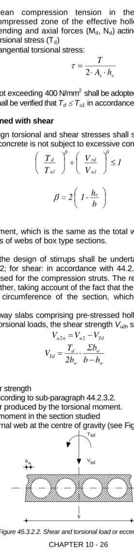
τ Tangential torsional stress: ) e e h A T ⋅ ⋅ = 2
τ
A value not exceeding 400 N/mm2 In every case, it shall be verified that T
shall be adopted for the steel’s design strength.
d≤ Tu1 45.3.2.2 Torsion combined with shear
in accordance with sub-paragraph 45.2.2.1
The concomitant design torsional and shear stresses shall satisfy the following condition in order to ensure that the concrete is not subject to excessive compression:
1
V
V
+
T
T
u1 rd u1 d
≤
β β in which : b h -1 2 = eβ
b Width of the element, which is the same as the total width of a solid section and the sum of the widths of webs of box type sections.
The calculations for the design of stirrups shall be undertaken separately; for torsion: in accordance with 45.2.2.2; for shear: in accordance with 44.2.3.2.2. In both calculations, the same angle θ shall be used for the compression struts. The reinforcements calculated in this way shall be added together, taking account of the fact that the torsion reinforcements shall be arranged on the outer circumference of the section, which is not compulsory for shear reinforcements.
If the section in one-way slabs comprising pre-stressed hollow core elements is subject to concomitant shear and torsional loads, the shear strength Vu2n
Td u n
u
V
V
V
2=
2−
shall be calculated on the basis of:
With w w w d Td b b Σb 2b T V − ⋅ = in which: Vu2n V
Net value of shear strength
u2
V
Shear strength according to sub-paragraph 44.2.3.2.
Td
T
Increase in shear produced by the torsional moment.
d
b
Design torsional moment in the section studied
w Width of the external web at the centre of gravity (see Figure 45.3.2.2)
V T sd sd bw b