NXDN
®
NXDN Forum
NXDN Technical Specifications
Part 2:
Conformance Test
Sub-part D:
Trunking Operation Test (Type-C)
NXDN TS 2-D Version 1.1
November 2011
Contents 1. Introduction ...1 2. References ...1 3. Abbreviations ...1 4. Outline...2 5. Test Procedures ...2 5.1. SU Testing...4
5.1.1. Group Voice Call Test ...4
5.1.1.1. Conference Group Call Test ...4
5.1.1.2. Broadcast Group Call Test ...8
5.1.2. Individual Voice Call Test ...8
5.1.2.1. Individual Call Test 1...9
5.1.2.2. Individual Call Test 2...9
5.1.2.3. Individual Call Test 3... 10
5.1.3. All Call Test ...12
5.1.3.1. Testing the Calling SU ... 13
5.1.3.2. Testing the Called SU ... 13
5.1.4. Short Data Call Test ... 13
5.1.4.1. Broadcast Short Data Call Test... 14
5.1.4.2. Unit to Unit Short Data Call Test ... 15
5.1.5. Data Call Test...17
5.1.5.1. Broadcast Data Call Test ... 18
5.1.5.2. Unit to Unit Data Call Test... 19
5.1.6. Status Notice Tests ... 24
5.1.6.1. Broadcast Status Call Test... 24
5.1.6.2. Status Call Test...25
5.1.7. Status Inquiry Test ... 27
5.1.7.1. Testing the Calling SU ... 28
5.1.7.2. Testing the Called SU ... 29
5.1.8. Remote Control Test ... 29
5.1.8.1. Testing the Calling SU ... 30
5.1.8.2. Testing the Called SU ... 31
5.1.9. Paging Test ...31
5.1.9.1. Testing the Calling SU ... 31
5.1.9.2. Testing the Called SU ... 32
5.1.10. Emergency Test ... 32
5.1.10.1. Emergency Call... 32
5.1.10.2. Emergency Alert... 32
5.1.11. Late Entry Test ... 33
5.1.11.1. Conference Group Call ... 33
5.1.12. Registration Test ...33
5.1.12.1. Case 1 - Registration Accept... 34
5.1.12.2. Case 2 - Registration Fail... 34
5.1.12.3. Case 3 - Registration Refuse ... 34
5.1.13. Registration Clear Test... 35
5.1.15. Group Registration Test ... 36
5.1.15.1. Case 1 - Group Registration Accept...36
5.1.15.2. Case 2 - Group Registration Fail... 37
5.1.15.3. Case 3 - Group Registration Refuse ...37
5.1.16. Authentication Tests... 37
5.1.16.1. Authentication Test during Registration Process...38
5.1.16.2. Authentication Test in Normal Process ...38
5.1.17. Site Roaming Test... 38
5.1.18. Priority Monitor Test ... 40
5.1.19. Time Out Timer Test ... 41
5.1.20. Transmission Trunking Test ... 42
5.1.21. Message Trunking Test... 42
5.1.22. Control Channel Switchover Test ... 43
5.1.23. Control Channel Add/Delete Test... 44
5.1.23.1. Control Channel Add... 44
5.1.23.2. Control Channel Delete ... 44
5.1.24. 1st and 2nd Control Channel Test... 44
5.1.25. Color Code Test ...45
5.1.26. Random Access Test ... 45
5.1.26.1. Random Access Test for Single Frame...46
5.1.26.2. Random Access Test for Multi Frame ...46
5.1.27. Encryption Test ...47
5.1.27.1. Encrypted Voice Call Test ... 47
5.1.27.2. Encrypted Short Data Call Test... 49
5.1.27.3. Encrypted Long Data Call Test ...51
5.2. TR Testing ...55
5.2.1. Control Channel Structure Test ... 55
5.2.2. Group Voice Call Test ... 57
5.2.2.1. Conference Group Call Test ... 57
5.2.2.2. Broadcast Group Call Test ... 57
5.2.3. Individual Voice Call Test ... 59
5.2.3.1. Individual Call Test 1... 59
5.2.3.2. Individual Call Test 2... 59
5.2.3.3. Individual Call Test 3... 60
5.2.4. All Call Test ...61
5.2.5. Short Data Call Test ... 61
5.2.5.1. Broadcast Short Data Call Test... 61
5.2.5.2. Unit to Unit Short Data Call Test ... 62
5.2.6. Data Call Test...63
5.2.6.1. Broadcast Data Call Test ... 63
5.2.6.2. Unit to Unit Data Call Test... 63
5.2.7. Status Notice Test ... 65
5.2.7.1. Broadcast Status Call Test... 65
5.2.7.2. Status Call Test...65
5.2.8. Status Inquiry Test ... 66
5.2.8.1. Case 1 – Status Inquiry Success ...66
5.2.9.1. Case 1 – Remote Control Success ...67
5.2.10. Emergency Test ... 68
5.2.10.1. Emergency Call... 68
5.2.11. Registration Test ...69
5.2.11.1. Case 1 - Registration Accept... 69
5.2.12. Registration Clear Test... 70
5.2.12.1. Case 1 - Registration Clear Accept ...70
5.2.13. Group Registration Test ... 71
5.2.13.1. Case 1 - Group Registration Accept...71
5.2.14. Authentication Test... 71
5.2.14.1. Authentication Test during Registration Process...72
5.2.14.2. Authentication Test in Normal Process ...72
5.2.15. Site Roaming Test... 72
5.2.16. Transmission Trunking Test ... 74
5.2.17. Message Trunking Test... 74
5.2.18. Color Code Test ...75
5.2.19. Random Access Test ... 75
5.2.19.1. Random Access Test for Single Frame...75
5.2.19.2. Random Access Test for Multi Frame ...75
5.2.20. Encryption Test ...76
6. Appendix ...77
6.1. Samples of Test Frame ...77
6.1.1. Samples of Short Data Call on Inbound ...77
6.1.2. Samples of Short Data Call on Outbound ...79
6.1.3. Samples of Scramble Encrypted Short Data Call on Inbound ...81
6.1.4. Samples of Scramble Encrypted Short Data Call on Outbound ...82
6.1.5. Samples of DES Encrypted Short Data Call on Inbound...84
6.1.6. Samples of DES Encrypted Short Data Call on Outbound ...86
6.1.7. Samples of AES Encrypted Short Data Call on Inbound ...88
6.1.8. Samples of AES Encrypted Short Data Call on Outbound ...89
7. Revision History ...92
Figures Figure 5.1-1 Configuration for Group Voice Call Test ...4
Figure 5.1-2 Configuration for Short Data Call Test...13
Figure 5.1-3 Configuration for SU Test ...34
Figure 5.1-4 Configuration for Site Roaming Test...39
Figure 5.1-5 Configuration for Priority Monitor Test ...40
Figure 5.2-1 Superframe on an RCCH ...56
Figure 5.2-2 Configuration for Control Channel Structure Test... 56
Figure 5.2-3 Configuration for Group Voice Call Test ...57
Figure 5.2-4 Configuration for Site Roaming Test...73
Figure 6.1-1 Data Frame Structure for Short Data Call (Inbound) ... 77
Figure 6.1-2 Data Frame Structure for Short Data Call (Outbound)... 79
Figure 6.1-4 Data Frame Structure for DES Encrypted Short Data Call (Outbound) ...86
Tables Table 5.1-1 VCALL_REQ Message for SU ...6
Table 5.1-2 VCALL_RESP Message for Interoperability Tester ...6
Table 5.1-3 VCALL_ASSGN Message for Interoperability Tester...7
Table 5.1-4 VCALL Message for SU...7
Table 5.1-5 DISC_REQ Message for SU...7
Table 5.1-6 DISC Message for Interoperability Tester...8
Table 5.1-7 VCALL_REC_REQ Message for Interoperability Tester... 11
Table 5.1-8 VCALL_REC_RESP Message for SU No. 2... 11
Table 5.1-9 VCALL_CONN_REQ Message for SU No. 2... 12
Table 5.1-10 VCALL Message for SU No. 2 ...12
Table 5.1-11 SDCALL_REQ (Header) Message for SU No. 1 and Interoperability Tester ... 17
Table 5.1-12 SDCALL_RESP Message for SU No. 2 and Interoperability Tester ...17
Table 5.1-13 DCALL_REQ/DCALL_REC_REQ Messages ... 22
Table 5.1-14 DCALL_RESP Message for Interoperability Tester ... 22
Table 5.1-15 DCALL_REC_RESP Message for SU No. 2... 23
Table 5.1-16 DCALL_ASSGN Message for Interoperability Tester ... 23
Table 5.1-17 DCALL (Header) Message for SU No. 1 and Interoperability Tester ...23
Table 5.1-18 DCALL_ACK Message for SU No. 2 and Interoperability Tester ...24
Table 5.1-19 STAT_REQ Message for SU No. 1 and Interoperability Tester ...27
Table 5.1-20 STAT_RESP Message for SU No. 2 and Interoperability Tester ...27
Table 5.1-21 STAT_INQ_REQ Message for SU No. 1 and Interoperability Tester...29
Table 5.1-22 STAT_INQ_RESP Message for SU No. 2 and Interoperability Tester...29
Table 5.1-23 REM_CON_REQ Message for SU No. 1 and Interoperability Tester ...31
Table 5.1-24 REM_CON_RESP Message for SU No. 2 and Interoperability Tester ... 31
Table 5.1-25 VCALL_ASSGN_DUP Message for Interoperability Tester ...33
Table 5.1-26 REG_REQ Message for SU ...35
Table 5.1-27 REG_RESP Message for Interoperability Tester ... 35
Table 5.1-28 REG_C_REQ Message for SU ...35
Table 5.1-29 REG_C_RESP Message for Interoperability Tester ... 36
Table 5.1-30 REG_COMM Message for Interoperability Tester ... 36
Table 5.1-31 GRP_REG_REQ Message for SU... 37
Table 5.1-32 GRP_REG_RESP Message for Interoperability Tester ... 37
Table 5.1-33 AUTH_INQ_REQ Message for Interoperability Tester... 38
Table 5.1-34 AUTH_INQ_RESP Message for SU ... 38
Table 5.1-35 REG_REQ Message for SU No. 1 in the case of Registration on Site 2...40
Table 5.1-36 REG_RESP Message for Interoperability Tester No.2 ... 40
Table 5.1-37 VCALL_ASSGN_DUP (or VCALL_ASSGN) Message for Interoperability Tester... 41
Table 5.1-38 VCALL_ASSGN Message for Interoperability Tester... 42
Table 5.1-39 CCH_INFO Message for Interoperability Tester ... 43
Table 5.1-40 CCH_INFO Message for Interoperability Tester ... 44
Table 5.1-41 SITE_INFO Message for Interoperability Tester ... 45
Table 5.1-43 VCALL Message (Encryption) ...53
Table 5.1-44 VCALL_IV Message (DES/AES Encryption)... 53
Table 5.1-45 Encryption Test Conditions for Voice Call...53
Table 5.1-46 SDCALL_REQ (Header) Message (Encryption) ... 53
Table 5.1-47 SDCALL_IV Message (DES/AES Encryption) ... 53
Table 5.1-48 Encryption Test Conditions for Short Data Call/ Data Call... 54
Table 5.1-49 DCALL (Header) Message (Scramble Encryption) ... 54
Table 5.1-50 DCALL (Header) Message (DES/AES Encryption)... 54
Table 5.2-1 SITE_INFO Message for TR...56
Table 5.2-2 Frame on an RCCH ...56
Table 5.2-3 VCALL_REQ Message for Interoperability Tester No. 1... 58
Table 5.2-4 VCALL_RESP Message for TR ...58
Table 5.2-5 VCALL_ASSGN/ VCALL_ASSGN_DUP Message for TR ...58
Table 5.2-6 DISC Message for TR...58
Table 5.2-7 VCALL_REC_REQ Message for TR...60
Table 5.2-8 VCALL_REQ_RESP Message for Interoperability Tester No. 2 ...60
Table 5.2-9 VCALL_CONN_REQ Message for Interoperability Tester No. 2 ...61
Table 5.2-10 SDCALL_REQ (Header) Message for Interoperability Tester No. 1 and TR ...62
Table 5.2-11 SDCALL_RESP Message for Interoperability Tester No. 2 and TR...62
Table 5.2-12 DCALL_REQ Message for Interoperability Tester No. 1... 64
Table 5.2-13 DCALL_REC_REQ Message for TR ... 64
Table 5.2-14 DCALL_REC_RESP Message for Interoperability Tester No. 2 ...64
Table 5.2-15 DCALL_ASSGN Message for TR ... 64
Table 5.2-16 STAT_REQ Message for Interoperability Tester No. 1 and TR ...66
Table 5.2-17 STAT_RESP Message for Interoperability Tester No. 2 and TR ...66
Table 5.2-18 STAT_INQ_REQ Message for Interoperability Tester No. 1 and TR ...67
Table 5.2-19 STAT_INQ_RESP Message for Interoperability Tester No. 2 and TR ...67
Table 5.2-20 REM_CON_REQ Message for Interoperability Tester No. 1 and TR...68
Table 5.2-21 REM_CON_RESP Message for Interoperability Tester No. 2 and TR...68
Table 5.2-22 VCALL_REQ Message for Interoperability Tester No. 1 (Emergency) ...69
Table 5.2-23 VCALL_ASSGN/ VCALL_ASSGN_DUP Message for TR (Emergency)...69
Table 5.2-24 VCALL Message for Interoperability Tester No. 1 and TR (Emergency) ...69
Table 5.2-25 REG_REQ Message for Interoperability Tester No. 1 ... 70
Table 5.2-26 REG_RESP Message for TR...70
Table 5.2-27 REG_C_REQ Message for Interoperability Tester No. 1... 70
Table 5.2-28 REG_C_RESP Message for TR ...70
Table 5.2-29 GRP_REG_REQ Message for Interoperability Tester No. 1...71
Table 5.2-30 GRP_REG_RESP Message for TR ...71
Table 5.2-31 AUTH_INQ_REQ Message for TR ... 72
Table 5.2-32 AUTH_INQ_RESP Message for Interoperability Tester No. 1 ...72
Table 5.2-33 VCALL_REC_REQ Message for TR No. 2 ... 73
Table 5.2-34 VCALL Message (Encryption) ...76
Table 5.2-35 VCALL_IV Message (DES/AES Encryption)... 76
Table 6.1-1 RAN and ID for Sample Frame Data ...77
Disclaimer
The information presented here is intended to be for clarification and/or information purpose only, and care has been taken to keep the contents as neutral and accurate as possible.
The use or practice of contents of the information may involve the use of intellectual property rights (“IPR”), including pending or issued patents, or copyrights, owned by one or more parties. The NXDN Forum makes no search or investigation for IPR, nor the NXDN Forum makes no arrangement of licensing negotiation for IPR between the user and the owner of IPR.
All warranties, express or implied, are disclaimed, including without limitation, any and all warranties concerning the accuracy of the contents, its fitness or appropriateness for a particular purpose or use, its merchantability and its non-infringement of any third party’s IPR.
The NXDN Forum expressly disclaims any and all responsibilities for the accuracy of the contents and makes no representations or warranties regarding the content’s compliance with any applicable statute, rule or regulation.
The NXDN Forum shall not be liable for any and all damages, direct or indirect, arising from or relating to any use of the contents contained herein, including without limitation any and all indirect, special, incidental or consequential damages (including damages for loss of business, loss of profits, litigation, or the like), whether based upon breach of contract, breach of warranty, tort (including negligence), product liability or otherwise, even if advised of the possibility of such damages.
The foregoing negation of damages is a fundamental element of the use of the contents hereof, and these contents would not be published by the NXDN Forum without such limitations.
Document Copyrights
This document is copyrighted by JVC KENWOOD Corporation and Icom Incorporated (“copyright holder”). No duplication, alteration or distribution of this document or any portion thereof shall take place without the express permission of the copyright holder except downloading from the NXDN Forum worldwide web. Reproduction, distribution, or transmission for any purpose in any form or by any means, electronic or mechanical, shall only be allowed with the express permission of the copyright holder.
Trademarks
NXDN® is a registered trademark of JVC KENWOOD Corporation and Icom Incorporated. AMBE+2™ is a trademark of Digital Voice Systems, Inc.
1. Introduction
This document provides the procedures and determination criteria of interoperability testing in Type-C trunked system for the trunking operation of the radio equipment which is designed in conformity with the NXDN Air Interface specifications.
This interoperability testing enables verification of interoperability among radio equipments manufactured by different manufacturers, or among different radio equipments manufactured by the same manufacturer, or of radio equipment of which the firmware is updated.
Defining test items for all of functions and conditions defined in the Air Interface specifications results in an enormous amount of documents and is unrealistic. Additionally defining the test procedures and related determination criteria for the system dependent functions is difficult. Hence, test items presented in this document do not contain all of functions and conditions and are limited to the scope that enables guarantee of a minimum interoperability. As well as conducting test items described in this document, it is recommended that every radio manufacturer verifies that radio equipments including items undefined by this document are in conformity with the NXDN specifications by conducting more detailed testing by referring to the Air Interface specifications.
The Common Air Interface Test as presented in REF [3] shall take place prior to this testing.
2. References
Reference documents are listed below.
REF [1] Part 1-A Common Air Interface Version 1.3 REF [2] Part 1-C Trunking Procedures Version 1.3 REF [3] Part 2-B Common Air Interface Test Version 1.1 REF [4] Part 2-C Basic Operation Test Version 1.2
3. Abbreviations
To help understand this document, abbreviations are listed below.
CAC Common Access Channel
CAI Common Air Interface
EFR Enhanced Full Rate
EHR Enhanced Half Rate
FACCH1 Fast Associated Control Channel 1 FACCH2 Fast Associated Control Channel 2
FSW Frame Sync Word
LICH Link Information Channel Long CAC Long Common Access Channel
RU Repeater Unit
SACCH Slow Associated Control Channel Short CAC Short Common Access Channel
SU Subscriber Unit
TC Trunking Controller
TR Trunking Repeater
TRS Trunking Repeater Site
4. Outline
There are two types of test methods available for interoperability testing of trunking operation as below:
Method 1: A method where an SU (or a TR) to be tested is tested by an interoperability tester
Method 2: A method where a testing takes place between an SU and TR
Method 1 is a test method using an interoperability tester. By verifying that the unit under test conforms to the specifications specified in Common Air Interface of the REF [1] and in Trunking Procedures of the REF [2], method 1 indirectly verifies that the unit under test has interoperability with other radio equipment which also conforms to the specifications.
Method 2 is a test method under the actual operation condition. This method allows testing without using an interoperability tester required by Method 1. If neither SU nor TR that has been verified in accordance with this document is available, both SU and TR shall be treated as units under test. Therefore, in the event that any test item fails, it is essential to specify which has nonconformity, either SU or TR. Also, even if a test item passes, it is necessary to fully verify that both SU and TR are in conformity with the specifications specified in REF [1] and REF [2]. A configuration diagram for testing is described in the configuration for Method 1; however, unless otherwise specified, either of two test methods can be employed. Configuration of an interoperability tester is not specified in this document; hence, the configuration shall be prepared using an appropriate method by the respective manufacturer that performs the test.
5. Test Procedures
In this section, test methods and judging criterions are presented.
Test methods for all functions are not described in this document. Functions not specified in this document shall be tested by the respective manufacturer using an appropriate test method. Each test method shall verify that the contents of messages exchanged between an SU and TR are correct and the SU and TR behave according to proper procedure upon transmit or receipt of these messages. Furthermore, testing for random access behavior is done in accordance with Section 5.1.26 and Section 5.2.19 to verify that the contents of the collision control field are correct and an SU behaves correctly in accordance with the contents.
A way of checking the data string of the layer 3 message and of the collision control field is not specified in this document. For example, it can be verified by outputting the received log data from a unit under test or interoperability tester, or by preparing a monitoring receiver which can receive both inbound signals from the unit under test and outbound signals from the interoperability tester.
Unless otherwise specified, the receive signal input level of the unit under test shall be -47 dBm or shall be equal to a significantly high level.
In the case of voice call, the unit under test shall be tested at 4800 bps/EHR, 9600 bps/EHR and/or 9600 bps/EFR in accordance with the mode implemented in it.
In other cases, the unit under test shall be tested at 4800 bps and/or 9600 bps in accordance with the modes implemented in it.
The data string is, in principle, described in the hexadecimal format; however, the letter “b” shall be suffixed in the case that the data string is described in the binary format.
In the transmit sequence of a data string, transmission begins with the leftmost value, and the rightmost value is sent at the end.
The setting values of Source ID and Destination ID used by tests are not defined in particular, so they can be selected in the range specified in REF [1].
A Tone Test Pattern or actual audio signals can be applied to the voice signals to be used for voice call testing. Contents of User Data to be used for data call testing are arbitrary.
An interoperability tester shall send a broadcast message such as SITE_INFO message, etc. to put an SU in the idle state. Unless otherwise specified, a Location ID to be used in a SITE_INFO message, etc. shall be configured as below:
Category = 01b (Local) System Code = 1 Site Code = 1
5.1. SU Testing
5.1.1. Group Voice Call Test
This test shall verify that contents of messages used for Group Voice Call are correct, that the unit under test correctly responds to these messages, and that a receiving unit outputs normal received audio signal.
This test includes the test methods for the following two modes: (1) Conference Group Call
(2) Broadcast Group Call
Figure 5.1-1 Configuration for Group Voice Call Test
Figure 5.1-1 shows the configuration diagram for testing. SU No. 1 and SU No. 2 shall be tested as the calling unit and the called unit respectively. The following 7 types of messages shall be applied.
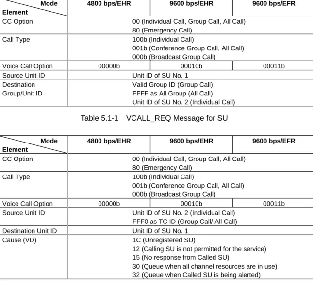
Table 5.1-1: VCALL_REQ message for SU
Table 5.1-2: VCALL_RESP message for Interoperability Tester Table 5.1-3: VCALL_ASSGN message for Interoperability Tester Table 5.1-4: VCALL message for SU
Table 5.1-5: DISC_REQ message for SU
Table 5.1-6: DISC message for Interoperability Tester Table 5.1-26: REG_REQ message for SU
5.1.1.1. Conference Group Call Test
In this test, parameters for messages to be used shall apply the values for Conference Group Call.
To verify the interoperability, a unit under test shall pass the test items specified in Section 5.1.1.1.1.1 and Section 5.1.1.1.2.
5.1.1.1.1. Testing the Calling SU
5.1.1.1.1.1. Case 1 - Group Call Permission
(1) Turn the SU No. 1 ON and keep it in the idle state.
(2) Verify that a VCALL_REQ message as described in Table 5.1-1 is sent by switching on the PTT control of SU No. 1.
Interoperability Tester
(3) Verify that SU No. 1 migrates to the specified RTCH, starts to transmit and sends a VCALL message as described in Table 5.1-4 when an interoperability tester sends a VCALL_ASSGN message as described in Table 5.1-3.
(4) Verify that SU No. 1 reverts to an RCCH when an interoperability tester sends a DISC message representing the disconnection by a timer as described in Table 5.1-6 on an RTCH.
5.1.1.1.1.2. Case 2 – Unregistered SU
(1) Turn the SU No. 1 ON and keep it in the idle state.
(2) Verify that a VCALL_REQ message as described in Table 5.1-1 is sent by switching on the PTT control of SU No. 1.
(3) Verify that SU No. 1 sends a REG_REQ message as described in Table 5.1-26 when an interoperability tester sends a VCALL_RESP message representing unregistered SU as described in Table 5.1-2.
5.1.1.1.1.3. Case 3 – Rejection by TC
(1) Turn the SU No. 1 ON and keep it in the idle state.
(2) Verify that a VCALL_REQ message as described in Table 5.1-1 is sent by switching on the PTT control of SU No. 1.
(3) Verify that SU No. 1 goes into the idle state when an interoperability tester sends a VCALL_RESP message as described in Table 5.1-2, which represents the calling SU is not permitted for the service.
5.1.1.1.1.4. Case 4 – Queue State
(1) Turn the SU No. 1 ON and keep it in the idle state.
(2) Verify that a VCALL_REQ message as described in Table 5.1-1 is sent by switching on the PTT control of SU No. 1.
(3) Verify that SU No. 1 goes into the queue state when an interoperability tester sends a VCALL_RESP message as described in Table 5.1-2, which represents the queue when all channel resources are in use.
(4) Verify that SU No. 1 migrates to the specified RTCH, starts to transmit and sends a VCALL message as described in Table 5.1-4 when an interoperability tester sends a VCALL_ASSGN message as described in Table 5.1-3 during the queue state.
5.1.1.1.1.5. Case 5 – Interruption of Queue State
(1) Keep the SU No. 1 in the state specified in step (3) of Section 5.1.1.1.1.4.
(2) Verify that SU No. 1 sends out a DISC_REQ message as described in Table 5.1-5 is sent out upon expiration of its Ts_busy timer.
5.1.1.1.2. Testing the Called SU
(1) Turn the SU No. 2 ON and keep it in the idle state.
(2) Verify that SU No. 2 migrates to the specified RTCH and goes into the receiving state when an interoperability tester sends a VCALL_ASSGN message as described in Table 5.1-3. (3) Verify that SU No. 2 outputs normal received audio signal when an interoperability tester
makes a voice call transmission.
(4) Verify that SU No. 2 reverts to an RCCH when an interoperability tester sends a DISC message representing the disconnection by a timer as described in Table 5.1-6 on an RTCH.
Mode Element
4800 bps/EHR 9600 bps/EHR 9600 bps/EFR
CC Option 00 (Individual Call, Group Call, All Call)
80 (Emergency Call)
Call Type 100b (Individual Call)
001b (Conference Group Call, All Call) 000b (Broadcast Group Call)
Voice Call Option 00000b 00010b 00011b
Source Unit ID Unit ID of SU No. 1
Destination Group/Unit ID
Valid Group ID (Group Call) FFFF as All Group (All Call) Unit ID of SU No. 2 (Individual Call) Table 5.1-1 VCALL_REQ Message for SU
Mode Element
4800 bps/EHR 9600 bps/EHR 9600 bps/EFR
CC Option 00 (Individual Call, Group Call, All Call)
80 (Emergency Call)
Call Type 100b (Individual Call)
001b (Conference Group Call, All Call) 000b (Broadcast Group Call)
Voice Call Option 00000b 00010b 00011b
Source Unit ID Unit ID of SU No. 2 (Individual Call)
FFF0 as TC ID (Group Call/ All Call)
Destination Unit ID Unit ID of SU No. 1
Cause (VD) 1C (Unregistered SU)
12 (Calling SU is not permitted for the service) 15 (No response from Called SU)
30 (Queue when all channel resources are in use) 32 (Queue when Called SU is being alerted) Table 5.1-2 VCALL_RESP Message for Interoperability Tester
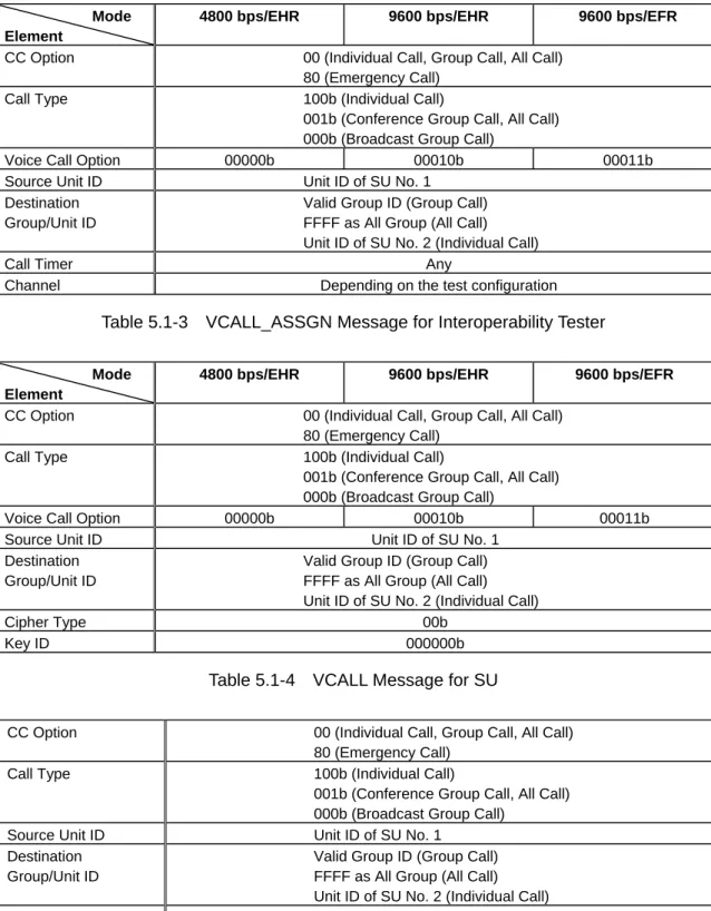
Mode Element
4800 bps/EHR 9600 bps/EHR 9600 bps/EFR
CC Option 00 (Individual Call, Group Call, All Call)
80 (Emergency Call)
Call Type 100b (Individual Call)
001b (Conference Group Call, All Call) 000b (Broadcast Group Call)
Voice Call Option 00000b 00010b 00011b
Source Unit ID Unit ID of SU No. 1
Destination Group/Unit ID
Valid Group ID (Group Call) FFFF as All Group (All Call) Unit ID of SU No. 2 (Individual Call)
Call Timer Any
Channel Depending on the test configuration
Table 5.1-3 VCALL_ASSGN Message for Interoperability Tester
Mode Element
4800 bps/EHR 9600 bps/EHR 9600 bps/EFR
CC Option 00 (Individual Call, Group Call, All Call)
80 (Emergency Call)
Call Type 100b (Individual Call)
001b (Conference Group Call, All Call) 000b (Broadcast Group Call)
Voice Call Option 00000b 00010b 00011b
Source Unit ID Unit ID of SU No. 1
Destination Group/Unit ID
Valid Group ID (Group Call) FFFF as All Group (All Call) Unit ID of SU No. 2 (Individual Call)
Cipher Type 00b
Key ID 000000b
Table 5.1-4 VCALL Message for SU
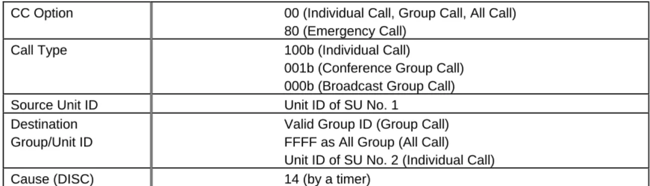
CC Option 00 (Individual Call, Group Call, All Call)
80 (Emergency Call)
Call Type 100b (Individual Call)
001b (Conference Group Call, All Call) 000b (Broadcast Group Call)
Source Unit ID Unit ID of SU No. 1
Destination Group/Unit ID
Valid Group ID (Group Call) FFFF as All Group (All Call) Unit ID of SU No. 2 (Individual Call)
Cause (DREQ) 14 (by a timer)
CC Option 00 (Individual Call, Group Call, All Call) 80 (Emergency Call)
Call Type 100b (Individual Call)
001b (Conference Group Call) 000b (Broadcast Group Call)
Source Unit ID Unit ID of SU No. 1
Destination Group/Unit ID
Valid Group ID (Group Call) FFFF as All Group (All Call) Unit ID of SU No. 2 (Individual Call)
Cause (DISC) 14 (by a timer)
Table 5.1-6 DISC Message for Interoperability Tester
5.1.1.2. Broadcast Group Call Test
In this test, parameters for messages to be used shall apply the values for Broadcast Group Call.
Tests for the calling SU shall be identical to those specified in Section 5.1.1.1.1 and tests for the called SU shall be identical to those specified in Section 5.1.1.1.2.
To verify the interoperability, a unit under test shall pass the test items specified in Section 5.1.1.1.1.1 and Section 5.1.1.1.2.
5.1.2. Individual Voice Call Test
This test shall verify that contents of messages used for Individual Voice Call are correct that the unit under test correctly responds to these messages, and that a receiving unit outputs normal received audio signal.
This test includes the test methods for the following three modes. To verify the interoperability, a unit under test shall pass the test item for at least one of procedure (1) to procedure (3).
(1) In the case that the availability of the called SU is not verified and a voice call transmission on an RTCH is started from the calling SU
(2) In the case that the availability of the called SU is verified and a voice call transmission on an RTCH is started from the calling SU
(3) In the case that the availability of the called SU is verified and a voice call transmission on an RTCH is started from the called SU
Figure 5.1-1 shows the configuration diagram for testing. SU No. 1 and SU No. 2 shall be tested as the calling unit and the called unit respectively. The following 11 types of messages shall be applied.
Table 5.1-1: VCALL_REQ message for SU
Table 5.1-2: VCALL_RESP message for Interoperability Tester Table 5.1-3: VCALL_ASSGN message for Interoperability Tester Table 5.1-4: VCALL message for SU
Table 5.1-5: DISC_REQ message for SU
Table 5.1-7: VCALL_REC_REQ message for Interoperability Tester Table 5.1-8: VCALL_REC_RESP message for SU No. 2
Table 5.1-9: VCALL_CONN_REQ message for SU No. 2 Table 5.1-10: VCALL message for SU No. 2
Table 5.1-26: REG_REQ message for SU
Values for Individual Call shall be applied to parameters for each Table.
5.1.2.1. Individual Call Test 1
To verify the interoperability, a unit under test shall pass the test items specified in Section 5.1.2.1.1.1 and Section 5.1.2.1.2.
5.1.2.1.1. Testing the Calling SU
5.1.2.1.1.1. Case 1 – Individual Call Permission
5.1.2.1.1.2. Case 2 – Unregistered SU
5.1.2.1.1.3. Case 3 – Rejection by TC
5.1.2.1.1.4. Case 4 – Queue State
5.1.2.1.1.5. Case 5 – Interruption of Queue State
Testing Procedures for these five cases shall be identical to those tests for Conference Group Call as described in Section 5.1.1.1.1.
5.1.2.1.2. Testing the Called SU
Testing Procedures shall be identical to those tests for Conference Group Call as described in Section 5.1.1.1.2.
5.1.2.2. Individual Call Test 2
To verify the interoperability, a unit under test shall pass the test items specified in Section 5.1.2.2.1.1 and Section 5.1.2.2.2.1.
5.1.2.2.1. Testing the Calling SU
5.1.2.2.1.1. Case 1 – Individual Call Permission
5.1.2.2.1.2. Case 2 – Unregistered SU
5.1.2.2.1.3. Case 3 – Rejection by TC
5.1.2.2.1.4. Case 4 – Queue State
5.1.2.2.1.5. Case 5 – Interruption of Queue State
Testing Procedures for these five cases shall be identical to those tests for Conference Group Call as described in Section 5.1.1.1.1.
5.1.2.2.1.6. Case 6 – No Response from Called SU
(2) Verify that a VCALL_REQ message as described in Table 5.1-1 is sent by switching on the PTT control of SU No. 1.
(3) Verify that SU No. 1 goes into the idle state when an interoperability tester sends a VCALL_RESP message as described in Table 5.1-2, which represents no response from the called SU.
5.1.2.2.2. Testing the Called SU
5.1.2.2.2.1. Case 1 – Incoming Call Permission
(1) Turn the SU No. 2 ON and keep it in the idle state.
(2) Verify that SU No. 2 sends a VCALL_REC_RESP message representing normal acceptance as described in Table 5.1-8 when an interoperability tester sends a VCALL_REC_REQ message as described in Table 5.1-7.
(3) Verify that SU No. 2 migrates to the specified RTCH, and goes into the receiving state when an interoperability tester sends a VCALL_ASSGN message as described in Table 5.1-3. (4) Verify that SU No. 2 outputs normal received audio signal when an interoperability tester
makes a voice call transmission.
(5) Verify that SU No. 2 reverts to an RCCH when an interoperability tester sends a DISC message representing the disconnection by a timer as described in Table 5.1-6 on an RTCH.
5.1.2.3. Individual Call Test 3
To verify the interoperability, a unit under test shall pass the test items specified in Section 5.1.2.3.1.1 and Section 5.1.2.3.2.1.
5.1.2.3.1. Testing the Calling SU
5.1.2.3.1.1. Case 1 – Individual Call Permission (1) Turn the SU No. 1 ON and keep it in the idle state.
(2) Verify that a VCALL_REQ message as described in Table 5.1-1 is sent by switching on the PTT control of SU No. 1.
(3) Verify that SU No. 1 goes into the waiting state for subsequent messages when an interoperability tester sends a VCALL_RESP message as described in Table 5.1-2, which represents the queue when a called unit is being alerted.
(4) Verify that SU No. 1 migrates to the specified RTCH and goes into the receiving state when an interoperability tester sends a VCALL_ASSGN message as described in Table 5.1-3. (5) Verify that SU No. 1 outputs normal received audio signal when an interoperability tester
makes a voice call transmission.
(6) Verify that SU No. 1 reverts to an RCCH when an interoperability tester sends a DISC message representing the disconnection by a timer as described in Table 5.1-6 on an RTCH.
5.1.2.3.1.2. Case 2 – Unregistered SU
5.1.2.3.1.3. Case 3 – Rejection by TC
5.1.2.3.1.4. Case 4 – Queue State
5.1.2.3.1.5. Case 5 – Interruption of Queue State
5.1.2.3.1.6. Case 6 – No Response from Called SU
Testing Procedures for these five cases shall be identical to those tests for Individual Call Test 2 as described in Section 5.1.2.2.1.
5.1.2.3.2. Testing the Called SU
5.1.2.3.2.1. Case 1 – Incoming Call Permission
(1) Turn the SU No. 2 ON and keep it in the idle state.
(2) Verify that SU No. 2 sends a VCALL_REC_RESP message representing normal acceptance as described in Table 5.1-8 when an interoperability tester sends a VCALL_REC_REQ message as described in Table 5.1-7.
(3) Verify that a VCALL_CONN_REQ message as described in Table 5.1-9 is sent by switching on the PTT control of SU No. 2.
(4) Verify that SU No. 2 migrates to the specified RTCH, starts to transmit and sends a VCALL message as described in Table 5.1-10 when an interoperability tester sends a VCALL_ASSGN message as described in Table 5.1-3.
(5) Verify that SU No. 2 reverts to an RCCH when an interoperability tester sends a DISC message representing the disconnection by a timer as described in Table 5.1-6 on an RTCH.
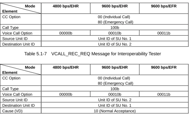
Mode Element
4800 bps/EHR 9600 bps/EHR 9600 bps/EFR
CC Option 00 (Individual Call)
80 (Emergency Call)
Call Type 100b
Voice Call Option 00000b 00010b 00011b
Source Unit ID Unit ID of SU No. 1
Destination Unit ID Unit ID of SU No. 2
Table 5.1-7 VCALL_REC_REQ Message for Interoperability Tester
Mode Element
4800 bps/EHR 9600 bps/EHR 9600 bps/EFR
CC Option 00 (Individual Call)
80 (Emergency Call)
Call Type 100b
Voice Call Option 00000b 00010b 00011b
Source Unit ID Unit ID of SU No. 2
Destination Unit ID Unit ID of SU No. 1
Cause (VD) 10 (Normal Acceptance)
Mode Element
4800 bps/EHR 9600 bps/EHR 9600 bps/EFR
CC Option 00 (Individual Call)
80 (Emergency Call)
Call Type 100b
Voice Call Option 00000b 00010b 00011b
Source Unit ID Unit ID of SU No. 2
Destination Unit ID Unit ID of SU No. 1
Table 5.1-9 VCALL_CONN_REQ Message for SU No. 2
Mode Element
4800 bps/EHR 9600 bps/EHR 9600 bps/EFR
CC Option 00 (Individual Call)
80 (Emergency Call)
Call Type 100b
Voice Call Option 00000b 00010b 00011b
Source Unit ID Unit ID of SU No. 2
Destination Unit ID Unit ID of SU No. 1
Cipher Type 00b
Key ID 000000b
Table 5.1-10 VCALL Message for SU No. 2 5.1.3. All Call Test
This test shall verify that contents of messages used for All Call are correct, that the unit under test correctly responds to these messages, and that receiving unit outputs normal received audio signal.
Figure 5.1-1 shows the configuration diagram for testing. SU No. 1 and SU No. 2 shall be tested as the calling unit and the called unit respectively. The following 7 types of messages shall be applied.
Table 5.1-1: VCALL_REQ message for SU
Table 5.1-2: VCALL_RESP message for Interoperability Tester Table 5.1-3: VCALL_ASSGN message for Interoperability Tester Table 5.1-4: VCALL message for SU
Table 5.1-5: DISC_REQ message for SU
Table 5.1-6: DISC message for Interoperability Tester Table 5.1-26: REG_REQ message for SU
Values for All Call shall be applied to parameters for each Table.
To verify the interoperability, a unit under test shall pass the test items specified in Section5.1.3.1.1 and Section 5.1.3.2.
5.1.3.1. Testing the Calling SU
5.1.3.1.1. Case 1 – All Call Permission
5.1.3.1.2. Case 2 – Unregistered SU
5.1.3.1.3. Case 3 – Rejection by TC
5.1.3.1.4. Case 4 – Queue State
5.1.3.1.5. Case 5 – Interruption of Queue State
Testing Procedures for these five cases shall be identical to those tests for Conference Group Call as described in Section 5.1.1.1.1.
5.1.3.2. Testing the Called SU
Testing Procedures shall be identical to those tests for Conference Group Call as described in Section 5.1.1.1.2.
5.1.4. Short Data Call Test
This test shall verify that contents of messages used for Short Data Call are correct, that the unit under test correctly responds to these messages, and that the called unit outputs normal received data.
This test includes the test methods for the following two modes. To verify the interoperability, a unit under test shall pass the test item for at least either of mode (1) or mode (2).
(1) Broadcast Short Data Call (2) Unit to Unit Short Data Call
Figure 5.1-2 Configuration for Short Data Call Test
Figure 5.1-2 shows the configuration diagram for testing. In the event that an SU by itself cannot realize the Short Data Call functions, testing can be done by connecting peripheral equipment such as a PC to the SU.
The following 3 types of messages shall be applied.
Table 5.1-11: SDCALL_REQ (Header) message for SU No. 1 Table 5.1-12: SDCALL_RESP message for SU No. 2
Table 5.1-26: REG_REQ message for SU
Interoperability Tester
SU No.1 SU No.2
SDCALL_REQ (User Data) messages are recommended to be constructed with User Data not exceeding 100 bytes. No contents of User Data are specified in this document.
5.1.4.1. Broadcast Short Data Call Test
In this test, parameters for messages to be used shall apply the values for Group Call.
To verify the interoperability, a unit under test shall pass the test items specified in Section 5.1.4.1.1.1 and Section 5.1.4.1.2.
5.1.4.1.1. Testing the Calling SU
5.1.4.1.1.1. Case 1 – Short Data Send Success
(1) Turn the SU No. 1 ON and keep it in the idle state.
(2) Verify that a SDCALL_REQ (Header) message as described in Table 5.1-11 and SDCALL_REQ (User Data) message are sent when SU No. 1 initiates a Short Data Call. (3) Verify that SU No. 1 goes into the idle state when an interoperability tester sends a
SDCALL_RESP message representing the Send Success as described in Table 5.1-12.
5.1.4.1.1.2. Case 2 – Unregistered SU
(1) Turn the SU No. 1 ON and keep it in the idle state.
(2) Verify that a SDCALL_REQ (Header) message as described in Table 5.1-11 and SDCALL_REQ (User Data) message are sent when SU No. 1 initiates a Short Data Call. (3) Verify that SU No. 1 sends a REG_REQ message as described in Table 5.1-26 when an
interoperability tester sends a SDCALL_RESP message representing unregistered SU as described in Table 5.1-12.
5.1.4.1.1.3. Case 3 – Rejection by TC
(1) Turn the SU No. 1 ON and keep it in the idle state.
(2) Verify that a SDCALL_REQ (Header) message as described in Table 5.1-11 and SDCALL_REQ (User Data) message are sent when SU No. 1 initiates a Short Data Call. (3) Verify that SU No. 1 goes into the idle state when an interoperability tester sends a
SDCALL_RESP message as described in Table 5.1-12 which represents the calling SU is not permitted for the service.
5.1.4.1.1.4. Case 4 – Full Retry
(1) Turn the SU No. 1 ON and keep it in the idle state.
(2) Verify that a SDCALL_REQ (Header) message as described in Table 5.1-11 and SDCALL_REQ (User Data) message are sent when SU No. 1 initiates a Short Data Call. (3) Verify that SU No. 1 sends a SDCALL_REQ (Header) message as described in Table 5.1-11
and SDCALL_REQ (User Data) message, when an interoperability tester sends a SDCALL_RESP message representing the Full Retry as described in Table 5.1-12.
5.1.4.1.2. Testing the Called SU
(1) Turn the SU No. 2 ON and keep it in the idle state.
(2) Verify that SU No. 2 correctly receives User Data when an interoperability tester sends a SDCALL_REQ (Header) message as described in Table 5.1-11 and SDCALL_REQ (User Data) message.
5.1.4.2. Unit to Unit Short Data Call Test
In this test, parameters for messages to be used shall apply the values for Individual Call.
The procedure for Unit to Unit Short Data Call is different between Confirmed format and Unconfirmed format.
To verify the interoperability, a unit under test shall pass the test item for at least either of the Confirmed format or the Unconfirmed format.
In the case of the Confirmed format, a unit under test shall pass the test items specified in Section 5.1.4.2.1.1 and Section 5.1.4.2.2.1.
In the case of the Unconfirmed format, a unit under test shall pass the test items specified in Section 5.1.4.2.1.2 and Section 5.1.4.2.2.2.
5.1.4.2.1. Testing the Calling SU
5.1.4.2.1.1. Case 1 (Confirmed) – Short Data Send Success
(1) Turn the SU No. 1 ON and keep it in the idle state.
(2) Verify that a SDCALL_REQ (Header) message as described in Table 5.1-11 and SDCALL_REQ (User Data) message are sent when SU No. 1 initiates a Short Data Call. (3) Verify that SU No. 1 goes into the waiting state for subsequent messages when an
interoperability tester sends a SDCALL_RESP message representing the Send Success as described in Table 5.1-12.
(4) Verify that SU No. 1 goes into the idle state when an interoperability tester sends a SDCALL_RESP message representing the Receive Success as described in Table 5.1-12.
5.1.4.2.1.2. Case 1 (Unconfirmed) – Short Data Send Success
(1) Turn the SU No. 1 ON and keep it in the idle state.
(2) Verify that a SDCALL_REQ (Header) message as described in Table 5.1-11 and SDCALL_REQ (User Data) message are sent when SU No. 1 initiates a Short Data Call. (3) Verify that SU No. 1 goes into the waiting state for subsequent messages when an
interoperability tester sends a SDCALL_RESP message representing the Send Success as described in Table 5.1-12.
5.1.4.2.1.3. Case 2 – Unregistered SU
5.1.4.2.1.4. Case 3 – Rejection by TC
5.1.4.2.1.5. Case 4 – Full Retry
Testing procedures for these three cases shall be common to the Confirmed format and Unconfirmed format, and identical to those tests for Broadcast Short Data Call as described in Section 5.1.4.1.1.
In the Confirmed format, the following test shall furthermore be done.
5.1.4.2.1.6. Case 5 (Confirmed) – No Response from Called SU
(1) Turn the SU No. 1 ON and keep it in the idle state.
(2) Verify that a SDCALL_REQ (Header) message as described in Table 5.1-11 and SDCALL_REQ (User Data) message are sent when SU No. 1 initiates a Short Data Call. (3) Verify that SU No. 1 goes into the waiting state for subsequent messages when an
interoperability tester sends a SDCALL_RESP message representing the Send Success as described in Table 5.1-12.
(4) Verify that SU No. 1 goes into the idle state when an interoperability tester sends a SDCALL_RESP message as described in Table 5.1-12 which represents no response from the called SU.
5.1.4.2.2. Testing the Called SU
5.1.4.2.2.1. Case 1 (Confirmed) – Receive Success
(1) Turn the SU No. 2 ON and keep it in the idle state.
(2) Verify that SU No. 2 correctly receives User Data and sends a SDCALL_RESP message, representing the Receive Success as described in Table 5.1-12, when an interoperability tester sends a SDCALL_REQ (Header) message as described in Table 5.1-11 and SDCALL_REQ (User Data) message.
5.1.4.2.2.2. Case 1 (Unconfirmed) – Receive Success
(1) Turn the SU No. 2 ON and keep it in the idle state.
(2) Verify that SU No. 2 correctly receives User Data when an interoperability tester sends a SDCALL_REQ (Header) message as described in Table 5.1-11 and SDCALL_REQ (User Data) message.
5.1.4.2.2.3. Case 6 (Confirmed) – Full Retry (1) Turn the SU No. 2 ON and keep it in the idle state.
(2) Verify that SU No. 2 sends a SDCALL_RESP message representing the Full Retry as described in Table 5.1-12, when an interoperability tester sends a SDCALL_REQ (Header) message as described in Table 5.1-11 and SDCALL_REQ (User Data) message containing incorrect Message CRC.
Mode Element
4800 bps 9600 bps
CC Option 00
Call Type 100b (Individual Call)
001b (Group Call)
Data Call Option 00000b 00010b
Source Unit ID Unit ID of SU No. 1
Destination Group/Unit ID
Unit ID of SU No. 2 (Individual Call) Valid Group ID (Group Call)
Cipher Type 00b
Key ID 000000b
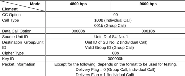
Packet Information Except for the following, depends on the format to be used for testing.
Delivery Flag = 0 (Group Call, Individual Call) Delivery Flag = 1 (Individual Call)
Table 5.1-11 SDCALL_REQ (Header) Message for SU No. 1 and Interoperability Tester
Mode Element
4800 bps 9600 bps
CC Option 00
Call Type 100b (Individual Call)
001b (Group Call)
Data Call Option 00000b 00010b
Source Unit ID Unit ID of SU No. 2 (Individual Call)
FFF0 as TC ID (Group Call)
Destination Unit ID Unit ID of SU No. 1
Cause (SS) 02 (Send Success)
1C (Unregistered SU) 08 (Full Retry)
12 (Calling SU is not permitted for the service) 01 (Receive Success)
15 (No Response from Called SU)
Error Block Flag Depends on the format to be used for testing.
Table 5.1-12 SDCALL_RESP Message for SU No. 2 and Interoperability Tester
5.1.5. Data Call Test
This test shall verify that contents of messages used for Data Call are correct, that the unit under test correctly responds to these messages, and that the called unit outputs normal received data.
This test includes the test methods for the following two modes. To verify the interoperability, a unit under test shall pass the test item for at least either of mode (1) or mode (2).
(1) Broadcast Data Call (2) Unit to Unit Data Call
Figure 5.1-2 shows the configuration diagram for testing. In the event that an SU by itself cannot realize the Data Call functions, testing can be done by connecting peripheral equipment such as a PC to the SU.
The following 9 types of messages shall be applied. Table 5.1-5: DISC_REQ message for SU
Table 5.1-6: DISC message for Interoperability Tester
Table 5.1-13: DCALL_REQ message and DCALL_REC_REQ message Table 5.1-14: DCALL_RESP message for Interoperability Tester
Table 5.1-15: DCALL_REC_RESP message for SU No. 2
Table 5.1-16: DCALL_ASSGN message for Interoperability Tester
Table 5.1-17: DCALL (Header) message for SU No. 1 and Interoperability Tester Table 5.1-18: DCALL_ACK message for SU No. 2 and Interoperability Tester Table 5.1-26: REG_REQ message for SU
It is recommended that DCALL (User Data) messages are constructed using User Data having a data length that is divided into multiple packets. No contents of User Data are specified in this document.
5.1.5.1. Broadcast Data Call Test
In this test, parameters for messages to be used shall apply the values for Group Call.
To verify the interoperability, a unit under test shall pass the test items specified in Section 5.1.5.1.1.1 and Section 5.1.5.1.2.
5.1.5.1.1. Testing the Calling SU
5.1.5.1.1.1. Case 1 - Group Call Permission
(1) Turn the SU No. 1 ON and keep it in the idle state.
(2) Verify that a DCALL_REQ message as described in Table 5.1-13 is sent when SU No. 1 initiates a Data Call.
(3) Verify that SU No. 1 migrates to the specified RTCH, starts to transmit and sends a DCALL (Header) message as described in Table 5.1-17 and DCALL (User Data) message, when an interoperability tester sends a DCALL_ASSGN message as described in Table 5.1-16. (4) Verify that SU No. 1 reverts to an RCCH when an interoperability tester sends a DISC
message representing the disconnection by a timer as described in Table 5.1-6 on an RTCH.
5.1.5.1.1.2. Case 2 – Unregistered SU
(1) Turn the SU No. 1 ON and keep it in the idle state.
(2) Verify that a DCALL_REQ message as described in Table 5.1-13 is sent when SU No. 1 initiates a Data Call.
(3) Verify that SU No. 1 sends a REG_REQ message as described in Table 5.1-26 when an interoperability tester sends a DCALL_RESP message representing unregistered SU as described in Table 5.1-14.
5.1.5.1.1.3. Case 3 – Rejection by TC
(1) Turn the SU No. 1 ON and keep it in the idle state.
(2) Verify that a DCALL_REQ message as described in Table 5.1-13 is sent when SU No. 1 initiates a Data Call.
(3) Verify that SU No. 1 goes into the idle state when an interoperability tester sends a DCALL_RESP message as described in Table 5.1-14, which represents the calling SU is not permitted for the service.
5.1.5.1.1.4. Case 4 – Queue State
(1) Turn the SU No. 1 ON and keep it in the idle state.
(2) Verify that a DCALL_REQ message as described in Table 5.1-13 is sent when SU No. 1 initiates a Data Call.
(3) Verify that SU No. 1 goes into the queue state when an interoperability tester sends a DCALL_RESP message as described in Table 5.1-14, which represents the queue when all channel resource are in use.
(4) Verify that SU No. 1 migrates to the specified RTCH, starts to transmit and sends a DCALL (Header) message as described in Table 5.1-17 and DCALL (User Data) message, when an interoperability tester sends a DCALL_ASSGN message as described in Table 5.1-16 during the queue state.
5.1.5.1.1.5. Case 5 – Interruption of Queue State (1) Turn the SU No. 1 ON and keep it in the idle state.
(2) Verify that SU No. 1 sends out a DISC_REQ message as described in Table 5.1-5 upon expiration of its Ts_busy timer.
(3) Subsequently, verify that SU No. 1 goes into the idle state. 5.1.5.1.2. Testing the Called SU
(1) Turn the SU No. 2 ON and keep it in the idle state.
(2) Verify that SU No. 2 migrates to the specified RTCH and goes into the receiving state when an interoperability tester sends a DCALL_ASSGN message as described in Table 5.1-16. (3) Verify that SU No. 2 correctly receives User Data when an interoperability tester sends a
DCALL (Header) message as described in Table 5.1-17 and DCALL (User Data) message. (4) Verify that SU No. 2 reverts to an RCCH when an interoperability tester sends a DISC
message representing the disconnection by a timer as described in Table 5.1-6 on an RTCH.
5.1.5.2. Unit to Unit Data Call Test
In this test, parameters for messages to be used shall apply the values for Individual Call.
The procedure for a Unit to Unit Data Call is different between Confirmed format and Unconfirmed format.
To verify the interoperability, a unit under test shall pass the test item for at least either of the Confirmed format or the Unconfirmed format.
In the case of the Confirmed format, a unit under test shall pass the test items specified in Section 5.1.5.2.1.1 and Section 5.1.5.2.2.1.
In the case of the Unconfirmed format, a unit under test shall pass the test items specified in Section 5.1.5.2.1.2 and Section 5.1.5.2.2.2.
5.1.5.2.1. Testing the Calling SU
5.1.5.2.1.1. Case 1 (Confirmed) – Individual Call Permission (1) Turn the SU No. 1 ON and keep it in the idle state.
(2) Verify that a DCALL_REQ message as described in Table 5.1-13 is sent when SU No. 1 initiates a Data Call.
(3) Verify that SU No. 1 migrates to the specified RTCH, starts to transmit and sends a DCALL (Header) message as described in Table 5.1-17 and DCALL (User Data) message, when an interoperability tester sends a DCALL_ASSGN message as described in Table 5.1-16. (4) Verify that SU No. 1 goes into the waiting state for subsequent messages when an
interoperability tester sends a DCALL_ACK message on an RTCH representing the Receive Success as described in Table 5.1-18.
(5) Verify that SU No. 1 reverts to an RCCH when an interoperability tester sends a DISC message representing the disconnection by a timer as described in Table 5.1-6 on an RTCH.
5.1.5.2.1.2. Case 1 (Unconfirmed) – Individual Call Permission (1) Turn the SU No. 1 ON and keep it in the idle state.
(2) Verify that a DCALL_REQ message as described in Table 5.1-13 is sent when SU No. 1 initiates a Data Call.
(3) Verify that SU No. 1 migrates to the specified RTCH, starts to transmit and sends a DCALL (Header) message as described in Table 5.1-17 and DCALL (User Data) message, when an interoperability tester sends a DCALL_ASSGN message as described in Table 5.1-16. (4) Verify that SU No. 1 reverts to an RCCH when an interoperability tester sends a DISC
message representing the disconnection by a timer as described in Table 5.1-6 on an RTCH.
5.1.5.2.1.3. Case 2 – Unregistered SU
5.1.5.2.1.4. Case 3 – Rejection by TC
5.1.5.2.1.5. Case 4 – Queue State
5.1.5.2.1.6. Case 5 – Interruption of Queue State
Testing procedures for these four cases shall be common to the Confirmed format and Unconfirmed format, and identical to those tests for Broadcast Data Call as described in Section 5.1.5.1.1.
5.1.5.2.1.7. Case 6 – No Response from Called SU (1) Turn the SU No. 1 ON and keep it in the idle state.
(2) Verify that a DCALL_REQ message as described in Table 5.1-13 is sent when SU No. 1 initiates a Data Call.
(3) Verify that SU No. 1 goes into the idle state when an interoperability tester sends a DCALL_RESP message as described in Table 5.1-14, which represents no response from the called SU.
.
5.1.5.2.1.8. Case 7 (Confirmed) – Full Retry (1) Perform step (1) to step (3) in Section 5.1.5.2.1.1.
(2) Verify that SU No. 1 sends a DCALL (Header) message as described in Table 5.1-17 and DCALL (User Data) message, when an interoperability tester sends a DCALL_ACK message representing the Full Retry as described in Table 5.1-18.
5.1.5.2.2. Testing the Called SU
5.1.5.2.2.1. Case 1 (Confirmed) – Incoming Call Permission
(1) Turn the SU No. 2 ON and keep it in the idle state.
(2) Verify that SU No. 2 sends a DCALL_REC_RESP message representing normal acceptance as described in Table 5.1-15, when an interoperability tester sends a DCALL_REC_REQ message as described in Table 5.1-13.
(3) Verify that SU No. 2 migrates to the specified RTCH and goes into the receiving state when an interoperability tester sends a DCALL_ASSGN message as described in Table 5.1-16. (4) Verify that SU No. 2 correctly receives User Data and sends a DCALL_ACK message
representing the Receive Success as described in Table 5.1-18, when an interoperability tester sends a DCALL (Header) message as described in Table 5.1-17 and DCALL (User Data) message.
(5) Verify that SU No. 2 reverts to an RCCH when an interoperability tester sends a DISC message representing the disconnection by a timer as described in Table 5.1-6 on an RTCH,.
5.1.5.2.2.2. Case 1 (Unconfirmed) – Incoming Call Permission
(1) Turn the SU No. 2 ON and keep it in the idle state.
(2) Verify that SU No. 2 sends a DCALL_REC_RESP message representing normal acceptance as described in Table 5.1-15, when an interoperability tester sends a DCALL_REC_REQ message as described in Table 5.1-13.
(3) Verify that SU No. 2 migrates to the specified RTCH and goes into the receiving state when an interoperability tester sends a DCALL_ASSGN message as described in Table 5.1-16. (4) Verify that SU No. 2 correctly receives User Data when an interoperability tester sends a
(5) Verify that SU No. 2 reverts to an RCCH when an interoperability tester sends a DISC message representing the disconnection by a timer as described in Table 5.1-6 on an RTCH,
5.1.5.2.2.3. Case 7 (Confirmed) – Full Retry (1) Perform step (1) to step (3) in Section 5.1.5.2.2.1.
(2) Verify that SU No. 2 sends a DCALL_ACK message representing the Full Retry as described in Table 5.1-18, when an interoperability tester sends a DCALL (Header) message as described in Table 5.1-17 and DCALL (User Data) message containing incorrect Message CRC.
Mode Element
4800 bps 9600 bps
CC Option 00
Call Type 100b (Individual Call)
001b (Group Call)
Data Call Option 00000b 00010b
Source Unit ID Unit ID of SU No. 1
Destination Group/Unit ID
Unit ID of SU No. 2 (Individual Call) Valid Group ID (Group Call)
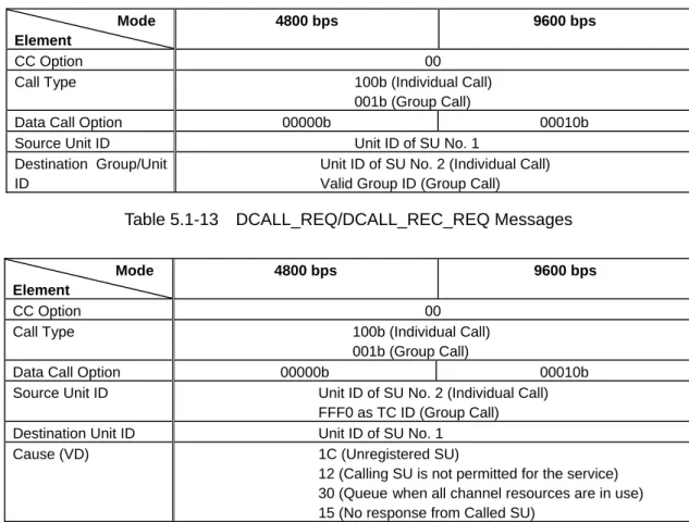
Table 5.1-13 DCALL_REQ/DCALL_REC_REQ Messages
Mode Element
4800 bps 9600 bps
CC Option 00
Call Type 100b (Individual Call)
001b (Group Call)
Data Call Option 00000b 00010b
Source Unit ID Unit ID of SU No. 2 (Individual Call)
FFF0 as TC ID (Group Call)
Destination Unit ID Unit ID of SU No. 1
Cause (VD) 1C (Unregistered SU)
12 (Calling SU is not permitted for the service)
30 (Queuewhen all channel resources are in use)
15 (No response from Called SU)
Mode Element
4800 bps 9600 bps
CC Option 00
Call Type 100b (Individual Call)
Data Call Option 00000b 00010b
Source Unit ID Unit ID of SU No. 2
Destination Unit ID Unit ID of SU No. 1
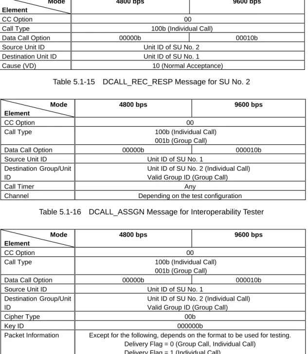
Cause (VD) 10 (Normal Acceptance)
Table 5.1-15 DCALL_REC_RESP Message for SU No. 2
Mode Element
4800 bps 9600 bps
CC Option 00
Call Type 100b (Individual Call)
001b (Group Call)
Data Call Option 00000b 000010b
Source Unit ID Unit ID of SU No. 1
Destination Group/Unit ID
Unit ID of SU No. 2 (Individual Call) Valid Group ID (Group Call)
Call Timer Any
Channel Depending on the test configuration
Table 5.1-16 DCALL_ASSGN Message for Interoperability Tester
Mode Element
4800 bps 9600 bps
CC Option 00
Call Type 100b (Individual Call)
001b (Group Call)
Data Call Option 00000b 000010b
Source Unit ID Unit ID of SU No. 1
Destination Group/Unit ID
Unit ID of SU No. 2 (Individual Call) Valid Group ID (Group Call)
Cipher Type 00b
Key ID 000000b
Packet Information Except for the following, depends on the format to be used for testing.
Delivery Flag = 0 (Group Call, Individual Call) Delivery Flag = 1 (Individual Call)
Mode Element
4800 bps 9600 bps
CC Option 00
Call Type 100b (Individual Call)
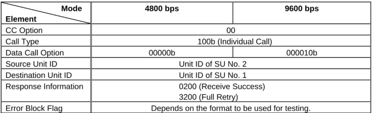
Data Call Option 00000b 000010b
Source Unit ID Unit ID of SU No. 2
Destination Unit ID Unit ID of SU No. 1
Response Information 0200 (Receive Success)
3200 (Full Retry)
Error Block Flag Depends on the format to be used for testing.
Table 5.1-18 DCALL_ACK Message for SU No. 2 and Interoperability Tester 5.1.6. Status Notice Tests
This test shall verify that contents of messages used for a Status Call are correct, and that the unit under test correctly responds to these messages.
This test includes the test methods for the following two modes. To verify the interoperability, a unit under test shall pass the test item for at least either of mode (1) or mode (2).
(1) Broadcast Status Call (2) Status Call
Figure 5.1-2 shows the configuration diagram for testing. In the event that an SU by itself cannot realize the Status Call functions, testing can be done by connecting peripheral equipment such as a PC to the SU.
The following 3 types of messages shall be applied.
Table 5.1-19: STAT_REQ message for SU No. 1 and Interoperability Tester Table 5.1-20: STAT_RESP message for SU No. 2 and Interoperability Tester Table 5.1-26: REG_REQ message for SU
5.1.6.1. Broadcast Status Call Test
In this test, parameters for messages to be used shall apply the values for Group Call.
To verify the interoperability, a unit under test shall pass the test items specified in Section 5.1.6.1.1.1 and Section 5.1.6.1.2.
5.1.6.1.1. Testing the Calling SU
5.1.6.1.1.1. Case 1 – Status Call Success
(1) Turn the SU No. 1 ON and keep it in the idle state.
(2) Verify that a STAT_REQ message as described in Table 5.1-19 is sent when SU No. 1 initiates a Status Call.
(3) Verify that SU No. 1 goes into the idle state when an interoperability tester sends a STAT_RESP message representing the Send Success as described in Table 5.1-20.
5.1.6.1.1.2. Case 2 – Unregistered SU
(1) Turn the SU No. 1 ON and keep it in the idle state.
(2) Verify that a STAT_REQ message as described in Table 5.1-19 is sent when SU No. 1 initiates a Status Call.
(3) Verify that SU No. 1 sends a REG_REQ message as described in Table 5.1-26 when an interoperability tester sends a STAT_RESP message representing unregistered SU as described in Table 5.1-20.
5.1.6.1.1.3. Case 3 – Rejection by TC
(1) Turn the SU No. 1 ON and keep it in the idle state.
(2) Verify that a STAT_REQ message as described in Table 5.1-19 is sent when SU No. 1 initiates a Status Call.
(3) Verify that SU No. 1 goes into the idle state when an interoperability tester sends a STAT_RESP message as described in Table 5.1-20 which represents the calling SU is not permitted for the service.
5.1.6.1.2. Testing the Called SU
(1) Turn the SU No. 2 ON and keep it in the idle state.
(2) Verify that SU No. 2 correctly receives a Status when an interoperability tester sends a STAT_REQ message as described in Table 5.1-19.
5.1.6.2. Status Call Test
In this test, parameters for messages to be used shall apply the values for Individual Call. The procedure for Status Call is different between Confirmed format and Unconfirmed format. To verify the interoperability, a unit under test shall pass the test item for at least either of the Confirmed format or the Unconfirmed format.
In the case of the Confirmed format, a unit under test shall pass the test items specified in Section 5.1.6.2.1.1 and Section 5.1.6.2.2.1.
In the case of the Unconfirmed format, a unit under test shall pass the test items specified in Section 5.1.6.2.1.2 and Section 5.1.6.2.2.2.
5.1.6.2.1. Testing the Calling SU
5.1.6.2.1.1. Case 1 (Confirmed) – Status Call Success
(1) Turn the SU No. 1 ON and keep it in the idle state.
(2) Verify that a STAT_REQ message as described in Table 5.1-19 is sent when SU No. 1 initiates a Status Call.
(3) Verify that SU No. 1 goes into the waiting state for subsequent messages when an interoperability tester sends a STAT_RESP message representing the Send Success as described in Table 5.1-20.
(4) Verify that SU No. 1 goes into the idle state when an interoperability tester sends a STAT_RESP message representing the Receive Success as described in Table 5.1-20.
5.1.6.2.1.2. Case 1 (Unconfirmed) – Status Call Success
(1) Turn the SU No. 1 ON and keep it in the idle state.
(2) Verify that a STAT_REQ message as described in Table 5.1-19 is sent when SU No. 1 initiates a Status Call.
(3) Verify that SU No. 1 goes into the idle state when an interoperability tester sends a STAT_RESP message representing the Send Success as described in Table 5.1-20.
5.1.6.2.1.3. Case 2 – Unregistered SU
5.1.6.2.1.4. Case 3 – Rejection by TC
Testing procedures for these two cases shall be common to the Confirmed format and Unconfirmed format, and identical to those testing for Broadcast Status Call as described in Section 5.1.6.1.1.
In the Confirmed format, the following test shall furthermore be done.
5.1.6.2.1.5. Case 4 (Confirmed) – No Response from Called SU
(1) Turn the SU No. 1 ON and keep it in the idle state.
(2) Verify that SU No.1 sends a STAT_REQ message as described in Table 5.1-19 when SU No. 1 initiates a Status Call.
(3) Verify that SU No. 1 goes into the waiting state for subsequent messages when an interoperability tester sends a STAT_RESP message representing the Send Success as described in Table 5.1-20.
(4) Verify that SU No. 1 goes into the idle state when an interoperability tester sends a STAT_RESP message as described in Table 5.1-20 which represents no response from the called SU.
5.1.6.2.2. Testing the Called SU
5.1.6.2.2.1. Case 1 (Confirmed) – Receive Success
(1) Turn the SU No. 2 ON and keep it in the idle state.
(2) Verify that SU No. 2 correctly receives a Status and sends a STAT_RESP message representing the Receive Success as described in Table 5.1-20, when an interoperability tester sends a STAT_REQ as described in Table 5.1-19.
5.1.6.2.2.2. Case 1 (Unconfirmed) – Receive Success
(1) Turn the SU No. 2 ON and keep it in the idle state.
(2) Verify that SU No. 2 correctly receives a Status when an interoperability tester sends a STAT_REQ message as described in Table 5.1-19.
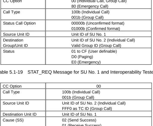
CC Option 00 (Individual Call, Group Call) 80 (Emergency Call)
Call Type 100b (Individual Call)
001b (Group Call)
Status Call Option 00000b (Unconfirmed format)
01000b (Confirmed format)
Source Unit ID Unit ID of SU No. 1
Destination Group/Unit ID
Unit ID of SU No. 2 (Individual Call) Valid Group ID (Group Call)
Status 01 to CF (User definable)
D0 (Paging) E0 (Emergency)
Table 5.1-19 STAT_REQ Message for SU No. 1 and Interoperability Tester
CC Option 00
Call Type 100b (Individual Call)
001b (Group Call)
Source Unit ID Unit ID of SU No. 2 (Individual Call)
FFF0 as TC ID (Group Call)
Destination Unit ID Unit ID of SU No. 1
Cause (SS) 02 (Send Success)
01 (Receive Success) 1C (Unregistered SU)
12 (Calling SU is not permitted for the service) 15 (No Response from Called SU)
Table 5.1-20 STAT_RESP Message for SU No. 2 and Interoperability Tester 5.1.7. Status Inquiry Test
This test shall verify that contents of messages used for Status Inquiry processing are correct, and that the unit under test correctly responds to these messages.
Figure 5.1-2 shows the configuration diagram for testing. In the event that an SU by itself cannot realize the Status Inquiry functions, testing can be done by connecting peripheral equipment such as a PC to the SU.
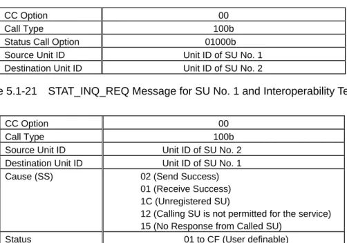
The following 3 types of messages shall be applied.
Table 5.1-21: STAT_INQ_REQ message for SU No. 1 and Interoperability Tester Table 5.1-22: STAT_INQ_RESP message for SU No. 2 and Interoperability Tester Table 5.1-26: REG_REQ message for SU
To verify the interoperability, a unit under test shall pass the test items specified in Section 5.1.7.1.1 and Section 5.1.7.2.1.