283
From:Methods in Molecular Biology, vol. 283: Bioconjugation Protocols: Strategies and Methods Edited by: C. M. Niemeyer © Humana Press Inc., Totowa, NJ
21
Peptide Nucleic Acid Microarrays
Anette Jacob, Ole Brandt, Achim Stephan, and Jörg D. Hoheisel
Summary
A fast and economical procedure for the production of peptide nucleic acid (PNA) microarrays is presented. PNA oligomers are synthesized in a fully automatic manner in 96-well plates using standard Fmoc chemistry. Subsequently, the oligomers are released from the support and spotted onto glass or silicone slides, which were activated by succinimidyl ester. This process allows for a concomitant purification of the oligomers directly on the chip surface. Although the terminal primary amino groups of the full-length products bind selec-tively to this surface, none of the byproducts of synthesis, such as truncated sequences or cleaved side chain protection groups, will bind and are therefore washed away. In this chapter, protocols are presented for the whole production process as well as sample hybridization.
Key Words: Peptide nucleic acid; parallel PNA synthesis, surface derivativation, DNA
hybridization. 1. Introduction
Deoxyribonucleic acid (DNA) microarrays have become an indispensable tool for the analysis of nucleic acids in a high-throughput format. Nowadays, hybridization analyses are routinely used for many purposes, particularly in combination with fluorescence detection. However, the performance of such analyses could be improved still, simplifying the processes involved or increas-ing sensitivity, for example. To such ends, we pursue the use of peptide nucleic acid (PNA) as the arrayed probe molecule (1). PNA is a synthetic substitute of DNA. Regular nucleobases are attached to a pseudopeptide backbone via a methylene-carbonyl spacer (2,3). PNA molecules exhibit excellent DNA and ribonucleic acid (RNA) binding capability, chemical stability, and resistance to enzymatic digestion (4). Because of the uncharged nature, PNA permits the hybridization of DNA samples in the absence of salt in the buffer because no interstrand repulsion as between two negatively charged DNA strands needs to
be counteracted. As a consequence, the target DNA has fewer secondary struc-tures and is more accessible to the probe molecules. Therefore, the fragmenta-tion of sample molecules before hybridizafragmenta-tion can be avoided. Furthermore, the use of PNA permits the adoption of an alternative detection mode, for which no labeling is required (5,6).
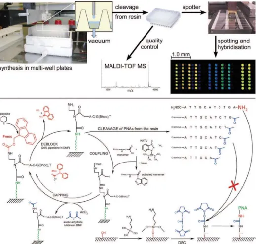
Reproducibility and reliability of PNA microarrays depend strongly on the quality of the oligomers on the chip surface. Also, relatively large numbers of oligomers are required for microarrays. However, only a rather small quantity of each oligomer is needed. For several years, we pursued the establishment of processes that permit the production of many PNA molecules of high quality at a reasonable cost. Here, we provide a detailed protocol based on our latest developments(6,7)for a fast and economical production of PNA microarrays. It combines parallel and automated PNA synthesis at a scale of 0.4 μmol with an on-chip purification technique. The whole process is summarized in Fig. 1. Because synthesis takes place on a resin that is placed in filter-bottom wells, the amount of PNA produced can be adapted to the actual needs by adjusting accordingly the amount of resin and the reagent volumes. Synthesis yields suf-fice for thousands of microarrays. PNA chips produced by this procedure have proven to be stable for a long time and can be reused in hybridization analyses many times over.
2. Materials
2.1. Parallel PNA Synthesis in Microwell Plates 2.1.1. Instrumentation
Synthesis is performed with an AutoSpot robot (INTAVIS Bioanalytical Instruments AG, Cologne, Germany) using 96-well plates with a frit in each well. Quality control is performed on a Reflex II MALDI-TOF mass spectrom-eter, (Bruker-Daltronik, Bremen, Germany).
2.1.2. Reagents
Rink resin LS (100–200 mesh, substitution of 0.2 mmol/g, seealsoNote 1) was obtained from Advanced ChemTech (Louisville, KY). Fmoc PNA mono-mers, Fmoc-AEEA–OH linker, and O-(7-azabenzotriazol-1-yl)-N,N,N',N '-tetramethyluronium hexafluoro-phosphate (HATU) were supplied by PE Biosystems (Framingham, MA). Fmoc-protected amino acids were obtained from Novabiochem–Calbiochem (Läufelfingen, Switzerland). Dimethylform-amide (DMF; SDS, Peypin, France) and 1-methyl-2-pyrrolidone (NMP; Sigma Aldrich, Munich, Germany) were both in a purity grade used for peptide chem-istry.N,N-diisopropylethylamine (DIEA), 2,6-lutidine, 1,2-dichloroethane, and
Fig. 1. Scheme of the production process. Parallel PNA synthesis based on Fmoc chemistry takes place in resin-filled microwell plates at a 0.4-μmol scale using an AutoSpot pipetting robot. Synthesis consists of iterative cycles of removing the Fmoc protection group (deprotection), activation of the monomers by adding HATU and base mix, followed by coupling to the growing chain and capping of unreacted, not elongated amino groups with acetic anhydride. Final products are released from the resin and transferred into another microwell plate. After quality control by MALDI-TOF MS, the crude oligomers are spotted onto glass or silicon slides by means of a pin spotter. Surfaces of the slides are silanized and activated with a succinimidyl ester that binds selectively the 5'-terminal primary amino group of the full-length product. The 3'-amino function represents an amide and is less reactive whereas acetylated amino groups of truncated sequences cannot bind at all. Thus purification of the crude products and spotting takes place simultaneously. The re-sulting microarrays are used in hybridization experiments.
trifluoroacetic acid (TFA) were supplied by Fluka (Steinheim, Germany); tri-isopropylsilane is from Sigma Aldrich (Munich, Germany).
For automated synthesis, the following solutions are prepared:
1. Fmoc monomer solutions of Fmoc-protected PNAs, amino acids, or AEEA–OH linker, respectively: each 0.3 M in NMP.
2. HATU solution: 0.6 M in DMF.
3. Base mix: 0.6 M DIEA and 0.9 M 2,6-lutidine in DMF.
4. Capping solution: 5% acetic anhydride and 6% 2,6-lutidine in DMF (v/v). 5. Deprotection solution: 20% piperidine in DMF (v/v).
6. Cleavage mixture: 80% TFA/5% triisopropylsilane in 1,2-dichloroethane. 7. Matrix solution for quality control via matrix-assisted laser
desorption/ioniza-tion time-of-flight (MALDI-TOF MS): 0.7 M3-hydroxypicolinic acid, 70 mM ammonium citrate in 50% aq. acetonitrile.
Protected from air and moisture, Fmoc monomer solutions can be stored in aliquots at –20°C for at least half a year. Before use, they should be mixed thoroughly because sometimes solubility problems arise, especially for the C monomer. The matrix solution can also be kept in aliquots at –20°C, whereas all other solutions are usually prepared freshly before synthesis.
2.2. Production of PNA Microarrays 2.2.1. Instrumentation
Contact printing device: SDDC-2 DNA Micro-Arrayer (Engineering Services Inc., Toronto, Canada) equipped with SMP3 pins (TeleChem International Inc., Sunnyvale, CA).
2.2.2. Support Media
1. Presliced, thermally oxidized silicon wafers of 2 × 2 cm (GeSiM, Rostock, Germany).
2. Nonderivatized microscope glass slides (Menzel-Gläser, Braunschweig, Germany). 2.2.3. Solutions for Surface Derivatization and Spotting Procedure
1. 10% NaOH (w/w).
2. Silanization mixture: 10 mL (3-aminopropyl)triethoxysilane in 200 mL of 95% aq. ethanol.
3. Activation mixture: 1.5 g of N-N'-disuccinimidyl carbonate and 5 mL of DIEA in 145 mL of dried acetone.
4. Betaine spotting buffer: 1 M betaine in water, pH adjusted to 7.5 with NaOH. 5. Deactivation mixture: 50 mMsuccinic anhydride, 150 mM1-methylimidazole in
1,2-dichloroethane.
6. Washing buffer, heated to 90°C: 5 mMsodium phosphate, 0.1% sodium dodecyl sulfate.
2.3. DNA Hybridization 2.3.1. Instrumentation
Slide incubation was performed in hybridization chambers of TeleChem (Sunnyvale, CA) or Hauser Präzisionstechnik (Vöhringen, Germany).
2.3.2. Hybridization Solution
0.1X SSarc buffer: 60 mM sodium chloride, 6 mMsodium citrate, 0.72% (v/v)N-lauroylsarcosine sodium salt solution.
3. Methods
3.1. Parallel PNA Synthesis in Microwell Plates
PNA synthesis is conducted in filter-bottom microwell plates by means of an AutoSpot pipetting robot. All reactions proceed at room temperature. Syn-thesis runs fully automatically overnight and starts with the Fmoc removal at the rink resin. First, the AutoSpot software is used to calculate the volumes that needed of HATU, the base mix solutions and each of the four monomers (A, G, C, T). The respective reagents are aspired by the dispenser needle and mixed thoroughly in prearranged tubes. After preactivation, the activated monomer solutions are pipetted, one at a time, into the respective wells. Because the robot was originally designed for peptide synthesis, the number of monomer solutions that can be worked with during a run is not limited to four. Therefore, all kinds of molecules, including amino acids, fluorescence labels, or linkers, can easily be introduced into the growing PNA chain using identical reaction conditions.
3.1.1. Synthesis Protocol
1. Prepare the respective solutions for the whole process and place them to the robotic system. This includes all monomer solutions required for the sequences of the desired oligomers, HATU, base mix, deprotection, and capping solutions, as well as DMF and 1,2-dichloroethane for the washing procedures (see also Subheading 2.).
2. Swell Fmoc-protected rink resin in DMF (20 mg/mL) for 1 h. Mix well and transfer 100 μL of this suspension into each well of the filter-bottom microtiter plate. A vacuum is applied to the plate for the removal of the reagents during synthesis.
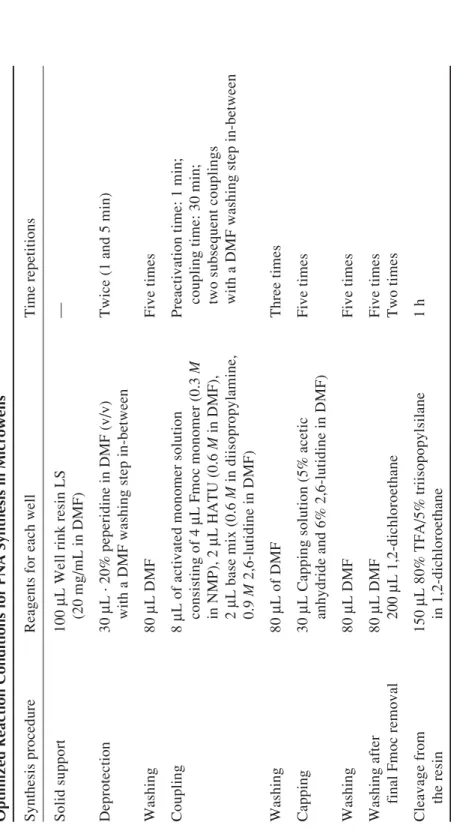
3. Enter into the computer the reaction conditions of the synthesis run as well as for each well the desired sequence of the PNA oligomer. The conditions that were found to be optimal for a 0.4 μmol scale synthesis are detailed in Table 1. 4. Start the synthesis process.
288 Table 1 Optimized Reaction Conditions for PNA Synthesis in Microwells Synthesis procedure
Reagents for each well
Time repetitions
Solid support
100
μ
L Well rink resin LS
— (20 mg/mL in DMF) Deprotection 30 μ L · 20% peperidine in DMF (v/v)
Twice (1 and 5 min)
with a DMF washing step in-between
Washing 80 μ L DMF Five times Coupling 8 μ
L of activated monomer solution
Preactivation time: 1 min;
consisting of 4
μ
L Fmoc monomer (0.3
M
coupling time: 30 min;
in NMP), 2
μ
L HATU (0.6
M
in DMF),
two subsequent couplings
2
μ
L base mix (0.6
M
in diisopropylamine,
with a DMF washing step in-between
0.9 M 2,6-lutidine in DMF) Washing 80 μ L of DMF Three times Capping 30 μ
L Capping solution (5% acetic
Five times
anhydride and 6% 2,6-lutidine in DMF)
Washing 80 μ L DMF Five times Washing after 80 μ L DMF Five times
final Fmoc removal
200 μ L 1,2-dichloroethane Two times Cleavage from 150 μ L 80% TFA/5% triisopopylsilane 1 h the resin in 1,2-dichloroethane
5. Synthesis stops with the final removal of the Fmoc group after the last cycle and subsequent washing. Place another microwell plate below the synthesis plate. Cleave the products from the resin by adding to each well 150 μL of cleavage mixture. After incubation, elute the released and completely deprotected oligomers with another 150 μL of the cleavage mixture into the second microwell plate.
6. Precipitate with 1 mL of ice-cold diethyl ether twice and dissolve after complete evaporation of any trades of ether each PNA in 100 μL of water. Store this solu-tion at 4°C until use (see also Note 2).
3.1.2. Quality Control
1. Calculate the amount of PNAs produced by UV measurement at 260 nm. This allows an early and rapid evaluation of the synthesis performance. A standard synthesis on 2 mg of resin should yield about 100 nmol of PNA product, although the yield varies with the length of the oligomer sequences, of course.
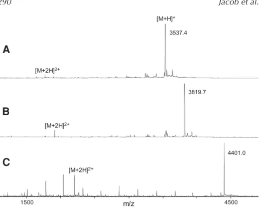
2. Mix 0.5 μL of the diluted PNA solution (1 μL of aliquot in 20 μL of water) with 0.5μL of matrix directly on the MALDI target and analyse the dried mixture by MALDI-TOF mass spectrometry. Typical spectra obtained in the positive ion mode are shown in Fig. 2.
3.2. Production of PNA Microarrays
For the production of PNA microarrays, either glass or thermally oxidized silicone slides are used as solid supports (see also Note 3). Slides are first silanized, then activated and finally used for the spotting procedure. All reac-tions are conducted identically for both silicone and glass slides and are per-formed at room temperature. Reaction conditions given below are used for the simultaneous surface derivatization of 20 slides in a slide holder. Modified aminosilane slides are protected from moisture and stored at 4°C until use. Activation of slides is always done directly before the spotting process. Stor-age of spotted and deactivated PNA slides is performed at 4°C.
3.2.1. Silanization
1. Wash silicone slides with dimethyl sulfoxide, ethanol, and water.
2. Etch all slides in 10% NaOH (w/w) for 1 h, followed by sonification for 15 min. 3. Wash the slides in water (until the pH is neutral) and ethanol.
4. Immerse the slides in silanization mixture [10 mL of (3-aminopropyl)trieth-oxysilan in 200 mL 95% aq. ethanol] for 1 h on a shaker and another 15 min in an ultrasonic bath.
5. Finally, wash the slides twice with ethanol, once with water, dry them under a stream of nitrogen, and heat them to 110°C for 20 min.
Fig. 2. Typical MALDI mass spectra of crude PNA products synthesized in microwell plates. (A)13-mer (TTGAATCGCTCGA); (B)modified 13-mer with lysine and AEEA-OH spacer modification (Lys-AEEA-AGCTTACGGATCA); and (C)13-mer with two AEEA-OH linker molecules (AEEA-AEEA-ACAAATTGCAGGATT).
3.2.2. Activation
1. Incubate aminosilane-derivatized slides with the activation mixture stirring gently for 2 h.
2. Wash twice with dried acetone and twice with 1,2-dichloroethane. After dry-ing with nitrogen, use the succinimidyl ester activated slides directly for PNA spotting.
3.2.3. Spotting, On-Chip PNA Purification, and Deactivation of the Surface 1. Dilute crude PNA products to a concentration of 200 μM in betaine spotting
buffer (seeNote 4).
2. Spot the dilutions of the crude PNA products on the activated slides and let them incubate at room temperature overnight.
3. Immerse the slides in the deactivation mixture shaking gently for 2 h.
4. Remove unbound full-length product as well as all byproducts by extensive wash-ing: twice with dichloroethane; twice with washing buffer (5 mMsodium
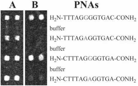
phos-Fig. 3. Detection of a SNP. PNA 12-mers of identical sequence but for a G or A nucleotide at their sixth or seventh position (marked bold), respectively, were spotted in duplicate on succinimidyl activated glass slides, with one row of buffer spots placed in-between. Slide A was hybridized with a polymerase chain reaction product of a heterozygous sample and slide B with a polymerase chain reaction product of a homozygous sample.
phate, 0.1% sodium dodecyl sulfate) that has been heated to 90°C; once with hot water (90°C) for 10 min, briefly with 1 M NaCl in aq. TFA, and finally with pure water.
5. Dry the slides with nitrogen and store them at 4°C or use them directly for hybridization experiments.
3.3. DNA Hybridization
The exact hybridization conditions depend strongly on the sequence of the oligomer probes and the type and complexity of the sample that is being ana-lyzed. Thus, only a set of conditions that is typical for the typing of single nucleotide polymorphisms is presented here. The result of such an analysis is shown in Fig. 3.
1. Add 18 μL of of the DNA onto an area of 2 × 2 cm and cover with a cover slip. 2. Incubate in a hybridization chamber at 38°C for 2 h.
3. Wash the slides twice with 0.1X SSarc of the same temperature, rinse with water, and dry with nitrogen.
4. Notes
1. Note that highly loaded resins are not suitable for PNA synthesis because the grow-ing oligomers will aggregate, which is a major reason for synthesis failure. There-fore, resins with a loading capacity higher than the one used here should be avoided. 2. The ether precipitation can be avoided. The PNAs are eluted from the resin with 200μL of water. After lyophilization, the oligomers are dissolved in 100 μL of water and stored at 4°C. Take care that the pH of the final spotting solution of the PNAs is 7.5. Although the cleaved Bhoc side chain groups are not removed by this procedure, purification takes place by the selective binding during the spot-ting procedure. Microarray performance is not affected by this simplification. 3. The combination of glass slides and fluorescence detection reflects the current
standard procedure. Silicone slides can be used for fluorescence detection also, although being slightly inferior to glass slides. However, they are superior for the detection of DNA binding by mass spectrometry (6). Here, glass slides exhibit charge effects.
4. To obtain homogeneous binding across the entire spot size and therefore homo-geneous signal intensity, it is absolute essential to reduce the speed of evapora-tion of the tiny droplets that are applied to the array surface, thus permitting a longer reaction time across the spot. This can be achieved by using spotting buff-ers with a high content of salts or addition of reagents that prevent evaporation, such as betaine (8), or both. However, because of the limited solubility of some PNA sequences, especially purine-rich sequences, buffers with high salt content proved to be inadequate, even though they are quite suitable for smaller sequences. Best results for sequences up to 20-mers are obtained with the spotting buffer used here.
Acknowledgments
This work was funded by the German Federal Ministry of Education and Research (BMBF).
References
1. Weiler, J., Gausepohl, H., Hauser, N., Jensen, O. N., and Hoheisel, J. D. (1997) Hybridisation based DNA screening on peptide nucleic acid (PNA) oligonucle-otide arrays. Nucleic Acids Res.25, 2792–2799.
2. Nielsen, P. E., Egholm, M., Berg, R. H. and Buchardt, O. (1991) Sequence-selec-tive recognition of DNA by strand displacement with a thymine-substituted polya-mide.Science254, 1497–1500.
3. Egholm, M., Buchardt, O., Christensen, L., Behrens, C., Freier, S. M., Driver, D. A., et al. (1993) PNA hybridizes to complementary oligonucleotides obeying the Watson-Crick hydrogen-bonding rules. Nature365, 566–568.
4. Demidov, V. V., Potaman, V. N., Frank-Kamenetskii, M. D., Egholm, M., Buchard, O., Sonnichsen, S. H., et al. (1994) Stability of peptide nucleic acids in human serum and cellular extracts. Biochem. Pharmacol.48, 1310–1313.
1
2
3
5. Arlinghaus, H. F., Ostrop, M., Friedrichs, O., and Feldner, J. (2003) Genome Diagnostic with TOF-SIMS. Appl. Surf. Sci.203/204, 689–692.
6. Brandt, O., Feldner, J., Stephan, A., Schröder, M., Schnölzer, M. Arlinghaus, H.F., et al. (2003) PNA-microarrays for hybridisation of unlabelled DNA-samples. Nucleic Acids Res.31, e119.
7. Jacob, A., Brandt, O., Würtz, S., Stephan, A., Schnölzer, M., and Hoheisel, J.D. (2003) Production of PNA-arrays for nucleic acid detection, in Peptide Nucleic Acids; Protocols and Applications (Nielsen, P.E., ed.), Horizon Bioscience, Wymondham, Norfolk, UK, pp, 261–279.
8. Diehl, F., Grahlmann, S., Beier, M., and Hoheisel, J. D. (2001) Manufacturing DNA-microarrays of high spot homogeneity and reduced background signal. Nucleic Acids Res.29, e38.
5 6