DoSAM – Domain-Specific Software
Architecture Comparison Model
*Klaus Bergner1, Andreas Rausch2, Marc Sihling1, Thomas Ternité2
* This work originates from a framework of research studies related to Modularity of Naval
Ships and funded by the German Procurement Agency Bundesamt für Wehrtechnik und Be-schaffung in Koblenz. 1 4Soft GmbH Mittererstraße 3 D-80336 Munich, Germany {bergner | sihling}@4soft.de 2
Technische Universität Kaiserslautern Fachbereich Informatik Arbeitsgruppe Softwarearchitektur
Gottlieb-Daimler-Straße D-67653 Kaiserslautern, Germany
{rausch | ternite}@informatik.uni-kl.de
Abstract. The architecture of an IT system is of crucial importance for its suc-cess. In order to assess architecture’s fitness, a number of standardized architec-ture evaluation methods have been proposed. Most of them are intended for the evaluation of a single architecture at a certain point in time. Furthermore, the results are often highly dependent on the person performing the evaluation. Thus, such methods cannot be used to compare and rate different architectures. The DoSAM method instead provides an evaluation framework for comparing different software architectures in a certain domain. After adapting this frame-work to the application domain at hand once, it can then be used repeatedly for all future evaluations in a methodical and reproducible way.
1 Introduction
The architecture of an IT system is a key success factor throughout its whole life cy-cle. During development, the architecture serves as a blueprint for all further design and implementation activities. Decisions met by the software architect determine qual-ity attributes of the final system like performance, scalabilqual-ity and availabilqual-ity [6]. If these decisions must be revised later on, substantial costs and delays may arise. Even more serious are the consequences for the operation and maintenance phase, during which the majority of costs accumulate [2, 3]. Only future-proof systems based on a clear, extensible structure can be adapted to new requirements with reasonable effort [5].
A method for assessing the strengths and shortcomings of system architectures is, therefore, very valuable in a multitude of situations. First of all, it allows the software architect to evaluate his decisions early in the software life cycle in order to avoid costly wrong decisions. Another application is the assessment of an existing legacy system in order to guide its redesign. Finally, potential customers may use such a method to rate the architectures of alternative systems during the tender process.
Today, a number of architecture evaluation methods exist, like SAAM and ATAM (both described in [1]). Most of them concentrate on the assessment of a single sys-tem’s architecture at a certain point of time, yielding a list of strengths and weaknesses (like SAAM) or of critical design tradeoffs (like ATAM). This is helpful for perform-ing an architecture review for a sperform-ingle system or for selectperform-ing a certain design variant for a special aspect of a system’s architecture.
However, the majority of current architecture evaluation methods do not support the comparison and rating of different architectures against each other. Note that the question here is not whether a certain detail of architecture A’s solution is better com-pared to architecture B’s solution – often, questions like that have an immediate, ob-vious answer. However, sacrificing an optimal detail solution in one area may pay off well in other areas, and may indeed be a deliberate and wise decision. To take aspects like this into consideration, and to shift the view from detail problems to the big pic-ture, assessment methods need to take a more general and more specific approach at the same time: More general, as they have to provide an assessment framework that is applicable for different software architectures, taking into account their strengths and weaknesses in order to ultimately get a single number on a scale. More specific, this weighting process must be based on clearly stated, transparent criteria derived from the given context and goals of the application domain.
The DoSAM method presented in this paper can bring together these contrasts. Its central idea is to provide a domain-specific software architecture comparison frame-work, which serves as a reference for different architectures in a certain domain. The comparison framework is derived from domain-specific scenarios, and comprehends as its two dimensions the necessary architecture services and the quality attributes for the domain under consideration.
The comparison framework is developed once and can then be used repeatedly to assess different architectures. This makes it valuable especially for application in the tender procedure, but also for comparing and selecting different overall approaches during system architecture design.
In principal, the DoSAM method may also be used for a single architecture review. Compared to other methods, the additional investment in the reference framework leads to additional costs, however. This weakness turns into strength when the archi-tecture is evaluated more than once, e.g. to support an iterative design process. Fur-thermore, the creation of the reference comparison framework usually brings addi-tional clarity, as it forces the assessor to think about the services and quality attributes necessary for the application domain.
The rest of the paper is structured as follows: First, in Section 2 we shortly outline the state of the art with respect to software architecture evaluation methods. Then, in Section 3 we give an overview over the proposed approach for a domain-specific software architecture comparison model. In Section 4 we present a sample application of DoSAM. Section 5 shows a part of the comparison framework for a specific quality attribute. A conclusion is given at the end of the paper in Section 6.
2 Related Work
Although commonly accepted in its importance for cost and quality of software sys-tems, the methodic assessment of software architectures is a rather young discipline. Most approaches rely on academic work presented in [1]:
SAAM - Software Architecture Analysis Method - Assessment of software architec-tures is done via scenarios, quality attributes and quality objectives. Scenarios provide an understanding of typical situations the architecture must cope with. Quality attrib-utes and quality objectives define the aspects of interest. During the process of as-sessment, the architectural approaches at hand are identified and evaluated with re-spect to the identified objectives. As a result, each architectural decision is associated with one or more risks to indicate problem areas.
ATAM – Architecture Tradeoff Analysis Method - In comparison to SAAM, this approach concentrates on finding crucial tradeoff-decisions and tries to detect the risks involved. Therefore, ATAM results in a good understanding of the pros and cons of each tradeoff and the implications of alternative solutions in the context of a given overall architecture.
CBAM – Cost-Benefit Analysis Method - The CBAM method [10] enhances ATAM by quantifications of the economic benefit and cost of architectural decisions.
ALMA – Architecture-Level Modifiability Analysis - Compared to the other ap-proaches, the ALMA method [11] has its focus on adaptation and modification scenar-ios for a given architecture and hence takes a special interest in the corresponding subset of quality attributes.
ARID – Active Reviews for Intermediate Designs - With a focus on the architecture of subsystems, this lightweight evaluation approach provides a procedure for the early phases of architectural design. The proposed technique is that of design reviews – a simple and effective, but rather subjective method.
SACAM – Software Architecture Comparison Analysis Method - This recently pro-posed method allows for comparison of a set of software architectures possibly of quite different application domains (cf. [8]). From a company’s business goals, the relevant quality criteria are derived and described by means of scenarios (similar to ATAM). Based on predefined metrics and architecture views, the evaluator looks for indicators to score each architecture with respect to the criteria.
The DoSAM method presented in this paper is based on similar base concepts, like scenarios and quality attributes. However, in addition, it brings in some new aspects:
• Apart from SACAM, none of the presented approaches allows for the comparison of several architectures of the same application domain. The evaluation procedure is highly tailored to the specifics of the architecture under consideration and depends on the person performing the evaluation. DoSAM strives for a more objective evaluation which can be repeated as requirements change over time.
• Like SACAM, the preparation of the comparison framework only needs to be done once for a certain application domain. Once the comparison framework has been adapted, it can be easily reused for additional archi-tectures or for re-evaluation after modifications of existing ones.
• In the process of a SACAM evaluation, the evaluator tries to find a mon level of abstraction for comparison by identifying a number of mon views. This may be quite difficult, especially when comparing pletely different architectures. DoSAM instead restricts itself to the parison of architectures in the same application domain based on a com-mon architecture blueprint. This blueprint serves as a conceptual frame-work, providing guidance for the assessor and simplifying the comparison process.
• Furthermore, DoSAM introduces architectural services as a means of de-scribing the basic functionality and purpose of the application domain in an abstract way. Compared to application scenarios, which are often very specific and may change over the lifetime of the architecture, architectural services provide a more high-level and stable view. Conceptually, services are roughly similar to SACAM view types, as they determine which archi-tectural aspects are assessed. However, in contrast to SACAM view types, services are motivated by the application domain and not by technical is-sues found in the architectural documentation (e.g. component dependency and complexity metrics, as mentioned as examples by SACAM).
To sum up, nowadays most architecture evaluations focus on the evaluation of a single architecture, not on the repeatable and standardized comparison of different architectural solutions. The only exception known to us is the SACAM method. Com-pared to it, DoSAM provides additional guidance, structure and stability due to the explicit consideration of a given application domain.
3 Domain-Specific Software Architecture Comparison Model
The DoSAM approach supports the evaluation and comparison of different architec-tural solutions within a given domain. Once a domain architecture comparison framework (DACF) has been created by an expert for a certain application domain, the concrete architecture evaluation (CAE) of the architecture in this domain can be performed following a standardized and repeatable process.
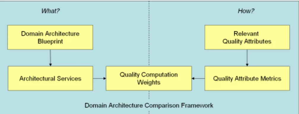
The structure of the DACF is shown in Fig. 1. Each of the inner boxes represents an intermediate result to be elaborated during the elaboration of the DACF.
Fig. 1. Domain Architecture Comparison Framework (DACF)
As can be seen, the framework consists of three main parts:
1. What is evaluated? - The domain architecture blueprint and the architec-tural services together form an abstract description schema for all archi-tectures in the application domain. The intention here is to find constitu-ents of the architectures that are inherent to the application domain at hand, and therefore inevitably represented in all imaginable solutions. Thereby, it is crucial to find the right level of abstraction: it must not be too detailed to be able to form a representative blueprint for the domain but it must not be to abstract to be able to reason about the relevant archi-tectural properties. Hence a domain specialist is needed to determine the proper architecture blueprint. Thereby, prevalent architectural styles and patterns in a given domain have to be taken into account (cf. [12]). An ex-ample for an abstract architecture service would be the data transfer ser-vice of a network-centric system, made up by a certain number of hard-ware and softhard-ware components in a specific architecture.
2. How is it evaluated? – The relevant quality attributes and the correspond-ing quality attribute metrics (one for each quality attribute) state in which respect the architectures are assessed and how the assessment of these cri-teria is performed. An example for a quality attribute would be the avail-ability, which could be measured by quality attribute metrics like the mean time to failure (MTTF) in a certain scenario.
3. What is important? – Finally, the quality computation weights in the mid-dle of the figure must be provided to state the relative importance of each application of a quality attribute metrics on an architectural service. For example, the assessor might decide that the availability of the data trans-fer service is very important in a certain application domain, at least in re-lation to the availability of other architecture services.
The possibility of adjusting the architectural services and the quality attributes, as well as the metrics and weights, makes the creation and fine-tuning of a DACF a chal-lenging task. However, when this task has been performed well, the resulting DACF can be intuitive and understandable even for persons with no deeper architectural
knowledge. At a high level, the DACF might capture statements like that military systems rely heavily on the availability, safety and security of communication ser-vices, whereas business systems might emphasize the performance of their transaction and storage services, for example.
As already stated, the creation of the DACF has to be performed only once for each application domain. Note that the modular structure of the DACF makes it possible to add new quality attributes and/or architecture services to the framework without breaking the existing framework.
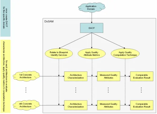
Fig. 2. DoSAM Application: DACF Creation and Concrete Architecture Evaluation (CAE)
After the creation of the DACF (shown in the upper part of Fig. 2) it can be applied to evaluate and compare the concrete architectures. This is a three-step process, which closely corresponds to the three main parts of the DACF shown in Fig. 1. It consists of the three following activities, which are performed for each concrete architecture to be evaluated:
1. Relate to Blueprint & Identify Services: The concrete architecture is re-lated to the architectural blueprint of the application domain, yielding the set of all hardware and software components and their connections that are relevant for the subsequent steps. This may result in one or more high-level architecture overview diagrams of the whole system. Based on that, the components involved in the realization of the identified architectural services are identified. For the data transfer service of a business
transac-tion system, this may, for example, result in hardware and software com-ponents like routers, firewalls, protocol stacks and caching software. 2. Apply Quality Attribute Metrics: The concrete service implementation of
the evaluated architecture is examined and assessed with respect to the identified quality attributes of the application domain. This is done by em-ploying the quality attribute metrics. Each of these metrics yields a single evaluation result on a normalized scale from 0 to 100. The data transfer service could, for example, be evaluated with respect to performance by assessing the combination of average throughput and average response time. A detailed example for the modifiability quality attribute metrics is given in Section 5.3.
3. Apply Quality Computation Technique: When all architecture services have been assessed with respect to all quality attributes, the evaluation re-sults may be entered into the weighted quality computation matrix. Again, this leads to a single, normalized evaluation result, characterizing the fit-ness of the architecture compared to other architectures and providing a hint for its absolute value with respect to the criteria captured within the DACF.
Provided that a well-designed DACF has been elaborated, the degree of freedom in performing the concrete architecture evaluation (CAE) will be rather low, ensuring a fair, repeatable evaluation of all architectures. This also means that a CAE can also be performed by people who are not highly-skilled application domain or architecture experts. Furthermore, if the application of the quality attribute metrics is supported by tools, the effort and time needed to perform a CAE can be kept very low.
4 Sample Application Domain
The following sections will briefly demonstrate the presented assessment process for the domain of IT architectures for modern naval crafts. We have chosen this applica-tion domain because DoSAM has been designed for a navy related study in the first place [9], but also because of the interesting architectural challenges involved:
• Compared to the clear, historic separation of duties for the different kinds of military ships, modern times demand highly flexible crafts that can eas-ily be modified to fit requirements of various mission scenarios (e.g. clearance of mines, evacuation, etc.)
• Cooperation with units of different, international armies steadily grows in importance and so does the ability of interaction and communication. Consequently, quality attributes like modularity, flexibility, and extensibility are of growing importance for the system architecture of modern military crafts. The chosen sample application domain is that of “modular ships” with the following understand-ing of modularity:
• All ships use a common, basic architecture which can be enhanced and specialized for all different kinds of crafts. This idea of a shared infra-structure platform results in a rather high degree of reuse and hence re-duces the costs for development, production, maintenance and education.
• A single ship can be equipped for a couple of different deployment scenar-ios, which is done either in the shipyard or in the field. That is, separate modules may be installed, each adding new features and services.
• Single modules can be standardized and standard COTS (commercial off-the-shelf) components can be used within the ship to further reduce devel-opment and maintenance cost.
To cope with the complexity of this modular approach, the demands on the quality of the underlying software and hardware infrastructure platform are very high. Its architecture is subject to assessment in the following chapters.
5 DoSAM Applied
This section offers a concrete example of the application of DoSAM as described in Section 3 in the sample application domain presented in Section 4. The presentation follows the three main areas of the DACF as shown in Fig. 1 as well as their applica-tion during the CAE as shown in Fig. 2. First, in Secapplica-tions 5.1 and 5.2 the domain architecture blueprint and the corresponding architecture services are described, re-spectively. In the following, the relevant quality attributes are described in Sec-tion 5.2, and an example for a detailed quality attribute metrics is given in SecSec-tion 5.3. Finally, the quality computation technique and its application are shown in Sec-tion 5.4.
5.1 Domain Architecture Blueprint
In order to evaluate architectures using the DACF evaluation model, it is necessary to create an architecture blueprint that shows a high level of universality. As already mentioned in Section 3, such a blueprint must not be too detailed to represent all con-crete domain architecture implementations and to support the mapping to real system architectures without constraining them. But the blueprint must not be to abstract, otherwise it will not be powerful enough to reason about the relevant architectural properties. It is not an easy task to find such a blueprint, but extensive usage of the knowledge of domain specialists will lead to good results. During development, uni-versality of the blueprint must be kept in mind.
In our sample application domain described in the previous section, a component based style seems to be a reasonable choice. Obviously, in other domains, other styles may be more appropriate. For example, one would expect pipes and filters in a signal processing application or, if applicable, the architecture might be oriented on event triggers [12].
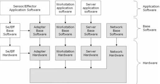
Fig. 3 shows a domain architecture blueprint for the sample application domain de-scribed in the previous section. As stated above, this blueprint follows an architectural style based on components. Obviously, this central platform consists of both hardware and software. Software can be split up into application software and base software. Since we want to assess only the fitness of the base platform, the application-specific software is not evaluated, visualized by the grey and white boxes in Fig. 3. Here, grey boxes represent components of the central platform, whereas white boxes show appli-cation-specific software and hardware that relies on it.
Base software and hardware are each subdivided into four categories:
• Adapters serve as interfaces for sensors and effectors and their software. Examples in the hardware domain are network adapters and hardware in-terfaces for sensors and effectors. In the software domain, generic device drivers fall into this category.
• Workstation hardware (consisting of CPU, main memory, data storage subsystem etc.) and software (e.g. operating system, communication soft-ware, mail client etc.)
• Server hardware and software, similar to their workstation counterparts.
• Network infrastructure consisting of switches, routers, firewalls (both hardware and software) and the network cables.
Fig. 3. Domain Architecture Blueprint for the Base Platform as part of the DACF
The categories depicted by grey boxes define the scope of the subsequent evalua-tion: During the assessment of the architectural services within the CAE, only compo-nents falling into one of these categories may be considered.
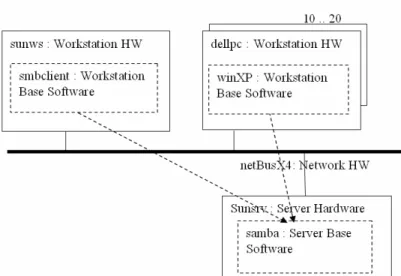
Fig. 4. Sample Part of an Architecture Overview Diagram created during CAE
To relate the concrete architecture to the blueprint architecture, one or more archi-tecture overview diagrams may be created. A simple representation could look as shown in Fig. 4, with software components shown as boxes with a dashed border and hardware components as boxes with a solid border. Alternatively, UML description techniques like deployment or component diagrams could also be used, as far as they can visualize the component categories of the blueprint architecture.
5.2 Architectural Services
The central platform is providing various services for the applications running on the ship. The following architecture services have been identified as crucial for the evaluation of different architectural solutions:
• Data transfer service: Achieves the transfer of heterogeneous data be-tween different applications and hardware modules with naval, military and civil application. The data transfer service must provide an infrastruc-ture for multimedia messages like video/speech, real-time data read in by sensors, and application messages between different application services.
• Data storage service: Achieves the persistent storage for real-time, mul-timedia, and application data as well as for arbitrary documents.
• Processing service: CPU power must be supplied for computationally ex-pensive tasks. This applies to both interactive and batch programs.
• System management service: Monitoring, administration and mainte-nance of the platform and its components must be achieved.
• Authentication/authorization service: Carries out the identification, au-thentication and authorization of users, applications and components.
• Presentation service: Achieves the presentation of GUIs and output on end devices like screens, printers etc.
These application-specific architecture services decompose the functionality of the underlying system into separate areas that can be evaluated independently.
Note that in order to assess each service for a given architecture during the CAE, it must be possible to identify the components that constitute its implementation. This may be done by marking the components on the architecture overview diagram, thus building a series of cut-out views from the overall architecture. Compared to the full architecture, the complexity of such an architecture service view will usually be greatly reduced, thus simplifying the evaluation of the services.
Very simple examples for architectural service cut-out views taken from Fig. 4 could range from all components (for the remote data storage service, in which all components might participate) to just the dellpc workstation hardware and software (for the presentation service, which could employ these workstations as terminals for other computers without screens).
5.3 Relevant Quality Attributes
Quality attributes like those found in the IEEE standard for quality attributes [7] de-fine criteria for a certain capability area of the architecture. In a military environment, especially on a ship, the following quality attributes play an important role in the ful-fillment of its purpose.
• Availability evaluates the capability of the architecture to provide con-tinuous functionality. It is defined as the relative amount of time the sys-tem functionality is accessible. Syssys-tem break downs and malfunctions have a negative effect on availability.
• Performance is influenced by parameters like throughput and response time. It measures how fast the architecture is and how many users can use it simultaneously.
• Usability characterizes the operability of the system. The user interfaces must provide fast support of routine processes on the ship. The architec-ture defines the framework to be used by applications in order to provide a user-friendly interface.
• Safety and Security as quality attribute evaluates the possibility of input errors and unwanted effects (safety) and the degree of protection against intended and unintended attacks (security).
• Modifiability defines the degree to which the architecture is configurable and extendible. This quality attribute includes aspects like developer friendliness, understandability and modularity. It has a crucial influence on the efforts and costs for necessary changes.
• Functionality valuates the completeness of the functionality and features provided for applications depending on the platform.
The description above stays at a very abstract level, of course. In order to be useful for a concrete evaluation, there must be unambiguous operational procedures that can
be applied in a repeatable way. During the creation of the DACF, we have devised a number of such procedures. As all of them yield as result a single number normalized by a scale from 0 to 100, we have called them quality attribute metrics. The following section gives an example.
5.4 Sample Quality Attribute Metrics – Modifiability
As an example for the evaluation procedure of a particular quality attribute, our qual-ity attribute metrics for the modifiabilqual-ity qualqual-ity attribute is described in the following. In the scenario described in Section 4, modifiability is a central aspect of the in-tended modularity of the ship. The following requirements have to be regarded in the evaluation of the architecture:
• The quality of the modular ship must not be degraded due to the change.
• Preparation and realization of the modification must be done in as little time as possible.
• The costs for preparation and realization of a change must be as low as possible.
In summary, the aspects quality, time, and costs enable an evaluation of modifiabil-ity of a modular ship. Time and costs can be determined and compared for different scenarios, but the resulting quality is not quantifiable as easily. In the following con-text, we assume that methods guaranteeing quality assurance like regression tests are used. This induces the assumption that the quality is not worsened by potential changes in the following context.
Concerning modifiability, the following types of change can be identified:
• CS: Change of solution: A change resulting from an alteration of the technical setup without any change in functionality that could be perceived by the user. The technical solution only defines how the system works.
• CF: Change of functionality: A change of functionality implies a change of any abilities of the system determining what the system does. This can include a change of solution, too.
The different change types (CS, CF) can be realized by the following change reali-zation types:
• CC: Change by configuration: The configuration parameters are the only parts of a component that underlie a change. This usually needs the least realization time.
• CI: Change by installation and deinstallation: New components are in-tegrated into the modular ship or removed, respectively. In order to be subject to a CI, the particular component and its modules must already be known and well specified. Otherwise, this could lead to a decreased qual-ity.
• CD: Change by development: The implementation of a component is changed or totally renewed. As mentioned before, quality assurance meth-ods have to be applied in order to prevent a decreasing quality due to newly implemented components.
Usually, a change by development directly implies a change by installation and deinstallation, whereas a CI usually contains a change by configuration.
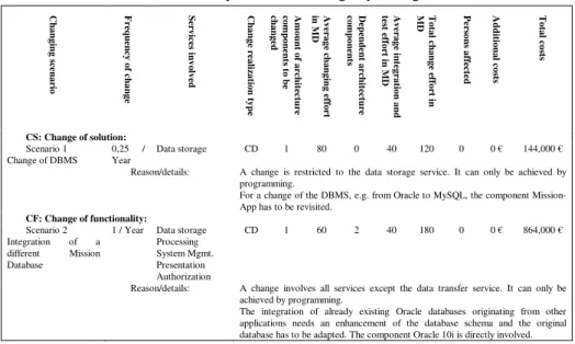
C h a n g in g s ce n a ri o F re q u en cy o f c h a n g e S er v ic es in v o lv ed C h a n g e re a liz a ti o n t y p e A m o u n t o f a rc h it ec tu re co m p o n en ts t o b e ch a n g ed A v er a g e ch a n g in g e ff o rt in M D D ep en d en t a rc h it ec tu re co m p o n en ts A v er a g e in te g ra ti o n a n d te st e ff o rt in M D T o ta l c h a n g e ef fo rt in M D Per so n s a ff ec te d A d d it io n a l c o st s T o ta l c o st s CS: Change of solution: Scenario 1 Change of DBMS 0,25 / Year Data storage CD 1 80 0 40 120 0 0 € 144,000 €
Reason/details: A change is restricted to the data storage service. It can only be achieved by programming.
For a change of the DBMS, e.g. from Oracle to MySQL, the component Mission-App has to be revisited.
CF: Change of functionality: Scenario 2
Integration of a different Mission Database
1 / Year Data storage Processing System Mgmt. Presentation Authorization
CD 1 60 2 40 180 0 0 € 864,000 €
Reason/details: A change involves all services except the data transfer service. It can only be achieved by programming.
The integration of already existing Oracle databases originating from other applications needs an enhancement of the database schema and the original database has to be adapted. The component Oracle 10i is directly involved.
Table 1: Exemplary Evaluation Table for Modifiability
In order to enable an evaluation of modifiability, different changing scenarios have to be identified first. These scenarios are written down in an evaluation table (see Table 1). Identifying these scenarios is part of adjusting the DACF and must therefore only be done once.
During architecture evaluation and comparison, for each architecture the change re-alization type of all scenarios has to be determined. Additionally, the following as-pects are written down: the amount of architecture components that are touched by the change, the amount of dependent architecture components, the average effort for inte-gration and testing, and for the change itself. Furthermore, the number of affected persons is noted and the additional are determined. When evaluating a concrete archi-tecture, these values are used to calculate the architecture specific costs to realize scenario
s
. The calculation rule is explained below.Every architecture is evaluated using the same scenarios. For each scenario s, the
total change effort
TChEff
s in man days (MD) is determined using the following equation:(
s s)
ss s
s
ACCh
ChEff
ACCh
ACDep
AITEff
TChEff
=
⋅
+
+
⋅
, (1)where ACChs are the average components to be changed, ChEffs is the average change effort for a component change, ACDeps are the dependent architecture com-ponents, and AITEffs is the average integration and testing effort. All these values are taken from the evaluation table exemplarily shown in Table 1.
The total costs
TC
sare determined using the following equation, where a MD is exemplarily set to a standard value like 1200 Euro. Being noted in the last column of Table 1,TC
s represents the architecture specific costs to realize scenarios
:(
)
(
s s s s)
s
s
Frq
CRT
TChEff
PA
C
TC
=
⋅
⋅
⋅
+
1
⋅
1200
+
, (2)where
Frq
s is the assumed frequency of a change,CRT
s is the change realization type,PA
s are the persons affected, andC
s are the additional costs in this scenarios
. The different change realization types each induce different factor values:• Change realization type CC:
CRT
s=
1
• Change realization type CI:
CRT
s=
2
• Change realization type CD:
CRT
s=
3
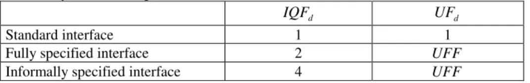
During architecture evaluation, not only potential changes and their costs are of in-terest. Understandability and applicability of the architecture itself have an influence on the quality of its modifiability, too. This holds true especially in a domain like a modular ship, where it is an important requirement that application components are exchangeable with low effort. In order to respect this, the architecture has to be evalu-ated regarding this aspect, too. This happens by determination of an architecture un-derstandability and applicability factor
AUAF
d for each architecture service d:d d d
IQF
UF
AUAF
=
⋅
, (3)where IQFd is the interface quality factor and UFd is the understandability factor
defined by the following table.
d
IQF UFd
Standard interface 1 1
Fully specified interface 2 UFF
Informally specified interface 4 UFF
Table 2: Definitions of interface quality factor and understandability factor Table 2 shows the factor value for the three possible interface types of an architecture service: standard interface, fully specified interface, and informally specified inter-face. It is assumed that there exist no unspecified interfaces. The understandability factor formulaUFF is defined by:
M
PTF
PAF
UFF
m M m m∑
∈⋅
=
, (4)where M is the set of parameters involved and M is its cardinality. The parameter amount factor PAFm has the value 1, if the amount of parameters in the method
m
has less than 10 parameters, otherwise it has the value 2. PTFm is the parameter type factor being determined by the following rule:
• Parameter type is a primitive data type: PTFm=1 • Parameter type is a complex data type: PTFm=2
• Parameter type is a complex data type with pointers: PTFm=4 • Parameter type is not defined: PTFm =16
An AUAF value of 1 indicates the best value that can be achieved. After having determined the costs for each change scenario and theAUAFd for all architecture services
d
, the intended metric value of the modifiability Modd of an architecture service can be determined by:TC
TC
TC
AUAF
Mod
s S s d d∑
∈+
⋅
−
=
101
, (5)where TC are the total project costs. The modifiability of a particular architecture service therefore is determined by the application understandability and applicability factor and the costs resulting from all changing scenarios that have been thought of during the development of the domain architecture comparison framework. This value is set in relation to the total project costs and then normalized to a maximum value of 100. A negative value is interpreted as 0.
5.5 Quality Computation Weights and Quality Computation Technique
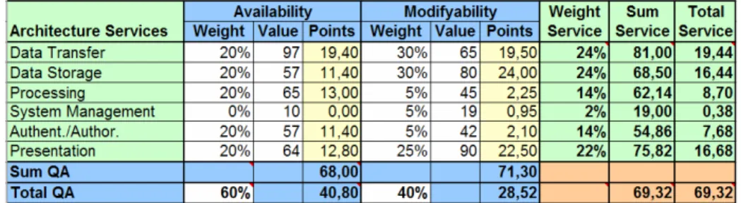
The quality computation technique is based on a two-dimensional matrix with the architecture services in its rows and the quality attributes in its columns.
For every combination of quality attribute and architecture service, the DACF pro-vides a quality attribute metrics yielding a metric percentage value normalized to the range from 0 to 100 (usually, the same quality attribute metrics will be used for all architecture service alike, although this is not strictly necessary). In Table 3, these values can be found in the Value columns. As can be seen in the example, the avail-ability of the data transfer service has reached a high evaluation result of 97%, indicat-ing the high fitness of the architecture with respect to this aspect.
In order to adapt the evaluation process to the requirements of the application do-main, the DACF creator has to weight the relative importance of the quality attributes as well as the contribution of each architecture service to each quality attribute (QA). These weights are part of the DACF and must therefore be used for all CAEs alike without changes. In Table 3, the quality attribute weights can be found in the white cells in the Total QA row, and the architecture service weights can be found in the Weight columns. As an example, the availability has been rated as more important compared to the modifiability (at a rate of 60 to 40). Furthermore, all services have been deemed equally important for the evaluation of the availability – with the single
exception of the system management service, which in the example has no relevance for the availability altogether.
Note that only the cells with a white background can be set by the user – all other contents are provided automatically by the DoSAM quality computation technique. This pertains to the weighted points in the Points columns as well as to all Sums and Totals. The sums characterize the relative fitness of the QAs and services. In the ex-ample, the architecture reaches a score of 68% with respect to the availability QA, and of 71,30% with respect to the modifiability QA, while its total weighted score is 69,32%. This end result number can now be compared with the respective end results for other architectures, allowing to rate the architectures against each other.
Table 3: Exemplary Evaluation Matrix for Two Quality Attributes
Another benefit of the two-dimensional evaluation matrix is that an architecture may not only be assessed with respect to its QAs, but also with respect to its architec-ture services. To allow for this, the matrix first computes architecarchitec-ture service weights (column Weight Service) and weighted service sums indicating the total fitness of the architecture services (column Sum Service). In the example, the relative importance of the data transfer service evaluation is 24%, whereas the system management service reaches only 2%, due to the low weights of 0% and 5% in the corresponding Weight columns. Furthermore, the score of the system management of 19% is coincidentally also much lower than the score of the data transfer service of 81%.
The Sum QA row and the Sum Service column together form a powerful analysis tool for the architect. Not only does he see how good the architecture comes out with respect to the quality attributes, but he can also trace this back to his design decisions for single architecture services. In the example, it could have been a wise decision to put no emphasis on the system management service, as it doesn’t contribute much to the overall fitness of the system.
6 Conclusion
In the paper, we have presented the DoSAM method for evaluating and comparing different architectures in a certain application domain. We have motivated the neces-sity for a new approach by comparing it to other architecture evaluation methods.
Our overview of DoSAM could of course not capture all details of the method. Therefore, we have restricted ourselves to a survey of the method’s base principles and a short presentation of some key results from an example application, namely, the
evaluation of IT application platforms for modular naval crafts. The actual, complete application example is much bigger – among others, it contains elaborated quality attribute metrics for all identified QAs, not only for the modifiability QA.
Our present experience with DoSAM up to now is encouraging: It seems to be a generally applicable and very flexible method suitable for all kinds of architectures. For the future, we plan to further elaborate and refine the DoSAM method based on additional evaluation experience. To do this, we will devise new or refined quality attribute metrics for the existing and for new QAs. In the following, better tool support for these QA metrics may then be developed in order to lower the time and effort necessary for concrete architecture evaluations. A long-term objective would be the design and implementation of a toolkit for rapidly building domain-specific architec-ture comparison frameworks based on existing quality attribute metrics.
References
1. P. Clements, R. Kazman, M. Klein: Evaluating Software Architectures, Methods and Case Studies, SEI Series in Software Engineering, 2002.
2. R. Harrison, ‘Maintenance Giant Sleeps Undisturbed in Federal Data Centers’, Computer-world, March 9, 1987.
3. B.P. Lientz and E.B. Swanson. Software Maintenance Management, Reading, MA: Addison-Wesley. 1980.
4. N. Lassing, P. Bengtsson, H. van Vliet and J. Bosch. Experiences with SAA of Modifiabil-ity, May 2000.
5. P. Bengtsson, J. Bosch, ‘Architecture Level Prediction of Software Maintenance’, The 3rd European Conference on Software Maintenance and Reengineering (CSMR'99), pp. 139-147, 1999.
6. L. Bass, P. Clements, R. Kazman, K. Bass. Software Architecture in Practice (Sei Series in Software Engineering). Addison-Wesley Publishing. 1998.
7. IEEE Std. 1061-1998, IEEE Standard for a Software Quality Metrics Methodology. 1998. 8. C. Stoermer, F. Bachmann, C. Verhoef, SACAM: The Software Architecture Comparison
Analysis Method, Technical Report, CMU/SEI-2003-TR-006, 2003
9. K. Bergner, A. Rausch, M. Sihling, Verfahren zur Bewertung von DV-Architekturen für das modulare Schiff, 4Soft Customer Study, 2004.
10. J. Asundi, R. Kazman, M. Klein, Using Economic Considerations to Choose Among Archi-tecture Design Alternatives, Technical Report, CMU/SEI-2001-TR-035, 2001.
11. P. Bengtsson, N. Lassing, J. Bosch, H. van Vliet, Architecture-Level Modifiability Analysis (ALMA), Journal of Systems and Software, Volume 69, Issue 1-2, 2004.
12. F. Buschmann, R. Meunier, H. Rohnert, P. Sommerlad, M. Stal, A System of Patterns, John Wiley&Sons, 1996.