221 | P a g e
WRINKLING PREDICTION ALGORITHM USING
LINEAR PERTURBATION TECHNIQUE IN ANSYS
FOR INFLATABLE STRUCTURES
Nidhin Mohan
M.Tech Student, Department of Mechanical Engineering,
Marbaselios College of Engineering and Technology
ABSTRACT
In this study, the static and modal analysis of spindle shaped Tensairity beam with hull element divided into three layers of equal thickness with different orientation was done. The parametric studies are done for thetensairity beam with materials, internal pressure and dimensions.From the modal analysis done, it was seen that there is variation between frequencies under two different pressures applied on the hull element. So the effect of pressure has to be taken into consideration in the design of Tensairity beam.Tensairity beam with chord and hull element made of low modulus of elasticity material produce higher natural frequencies than chord element made of high modulus of elasticity material.From modal analysis,it was found that the dimensions of tension and compression element has great influence in designing of the beam.Tensairity beam with hull element made of low modulus of elasticity fabric material shows greater displacement than the Tensairity beam with hull element made of high modulus of elasticity fabric material.Tensairity beam with low internal pressure on hull element shows greater displacement than beam with high internal pressure on hull element.
Keywords: Internal Pressure, Modal Analysis, Modulus of Elasticity Static Analysis, Tensairity
Beam.
I. INTRODUCTION
It seems to be part of our human nature to push the limits. Skyscrapers are growing higher, the maximal span of
bridges and roof structures are increasing day by day. The limit of feasibility is set by physical constraints or by
complexity or by the economic conditions. The development on all these frontiers are advancing very fast, new
concepts and materials are developing day by day. Air as a structural element has quite some history. From hot
air balloons to air houses and tires: pneumatic structures have found in the course of time their market niches.
Attracted by the light weight and availability of the material, many engineers have looked for applications of
inflated structures. However, in most respects, the limit of pneumatic structures turns out to be a physical one:
the load bearing capacity.
While voluminous inflated structures such as airhouses work reasonably well with low air pressure, slender
structures with small curvatures can only maintain some stiffness with increasingly large air pressure. In the new
structural element Tensairity, the pneumatic fabric structures are combined with conventional elements as cables
222 | P a g e
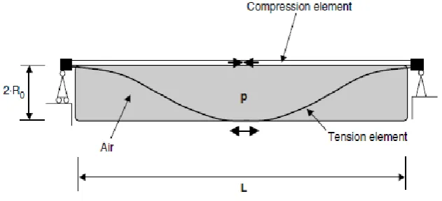
1.1 Structure and Behaviour of Tensairity Beam
A Tensairity girder consists of a tension element and a compression element separated by an inflated fabric
structure, so that these act as a spacer between tension and compression element. Compression element and
tension element are connected with each other at both ends of the beam to close the flow of force. The role of
the compressed air inside the hull is to facilitate the load transfer between the tension and the compression
element and to stabilize the compression element against buckling. The first investigated Tensairity beams were
done on a cylindrical form. The tension element used here are two cables which are spiralled around the
cylindrical air beam and which are connected on each end with the linear compression element. The
compression element is tightly connected with the membrane so as stabilize against buckling. The representation
of a typical cylindrical tensairity beam simply supported at the ends is shown in fig 1.1.
Fig 1. Representation of cylindrical shaped Tensairity beam
1.2 Spindle Shaped Tensairity Beam
While the first Tensairity beams were based on a cylindrical form, further investigations revealed, that cigar
shaped or spindle shaped Tensairity girders as shown in Fig.1.2 are much stiffer than the former That is, the
deflection of a spindle Tensairity girder is smaller than the deflection of a cylindrical girder with the same
length, maximal diameter and pressure under same loading conditions. Another difference with the spindle
Tensairity girder is that the two helical cables of the cylindrical girder degenerate to a single tension element in
the spindle. As the tension element is no more spiraled around the tube, it can have some bending stiffness and
can be used as a compression element, too. Therefore, spindle shaped Tensairity girders can withstand both
positive and negative loads. This is especially good for roof applications with positive snow loads and negative
wind loads.
The spindle shaped Tensairity girder of Fig. 1.2 can be made completely symmetric and a tension element
becomes a compression element and vice versa depending on the loading conditions. Asymmetric spindles can
also be considered as Tensairity. A typical form of an asymmetric spindle is when the upper chord is an arc and
the lower chord is a straight line. As in a bow, the tension element can be prestressed even with zero pressure in
the air beam and thus the structure remains stable even under complete air loss. The asymmetric spindle can be
designed to withstand the dead load of the structure with zero pressure whereas the function of the compressed
air is to withstand the live load. This important safety feature is adapted in the roof of the parking garage
inMontreux. Finally, the spindle shape of beam allows more dynamic forms as compared to the cylindrical
223 | P a g e
The recent Tensairity applications as the roof of the parking garage in Montreux where based on spindle shaped
Tensairity girders. The basic principles for spindle shaped and cylindrical shaped girders are same. The role of
the compressed air in the spindle is to stabilize the element under compression against buckling, it acts as a
spacer between the lower and upper chord and it facilitates the load transfer between the upper and lower chord
by means of the pressurized membrane.
Fig 2. Representation of spindle shapeTensairity beam
II.WRINKLING PHENOMENON
Thin membranes wrinkle whenever they are subjected to compressive load. This is due to the inherently small
bending resistance of membrane structures which buckle out-of-plane under the action of even small in-plane
compressive stress. This phenomenon is common and it can be observed in many structures in daily use, ranging
from umbrellas and temporary tents to large fabric roofs for airports and stadiums. Wrinkling is not a concern
for designing small structures because it has no structural consequences. More often a compensation scheme is
used, in which the fabric is cut to a smaller size than that required to generate purely the geometric shapes that
are required according to the form-finding process. Additional stretching of the fabric is thus required in order to
eliminate potential wrinkles.The presence of wrinkles in membrane structures may significantly influence static
and dynamic behaviour of space systems containing membranes. It is, therefore important to develop
computationally effective analysis methods for the prediction of wrinkle formation and evolution in membranes.
A buckling solution and a non-linear post buckling solution were employed for the wrinkling analysis of a
tensioned Kapton square membrane.
2.1 Types of Wrinkles
Wrinkles due to loading or boundary conditions are completely reversible if the membrane does not yield. These
wrinkles are termed structural/elastic wrinkles; their magnitude varies with the loading and boundary conditions.
Wrinkles where the material yields are permanent and irreversible, and are termed material/plastic wrinkles.
This type of wrinkles can be random and can be thought of as an initial set of very extreme imperfections. Only
structural wrinkles are considered in the present study.
As the application of Tensairity structure increases, it is proposed to study the behaviour of the spindle shaped
Tensairity beam under different loading and by changing various parameters. A beam element is being analysed
224 | P a g e
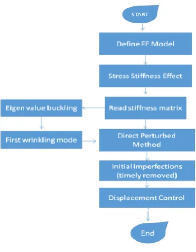
2.2 Wrinkling Computation Procedure
Fig 3.Flowchart of wrinkling computation
In the past methods, the imperfections are generated from the first wrinkle mode or the combination of the
several modes by multiplying by a scale factor. These imperfections cannot be removed from the model which
will influence the post wrinkling behaviours. In order to accurately perform the wrinkling analysis, the idea of
the Modified Displacement Component method by using the direct perturbed method in the simulation. The
basic of the direct perturbed method is to apply some small out-of-plane forces on the membrane surface to
induce the imperfections, and further to induce the wrinkle. After that, these imperfections are timely removed
from the model by deleting those out-of-plane forces.
Where, we should take care of two key problems. Firstly, the detailed imperfections should be based on the first
wrinkling mode which is obtained from an eigenvalue buckling analysis, including the imperfection amplitude,
the imperfection region and the imperfection direction. In other words, these imperfections generated by the
out-of-plane forces have the quantitative characteristics, and they are not random distributions. Above all, we have a
default rule that the imperfection amplitude should be at the same magnitude of the membrane thickness.
Secondly, the equal numbers of positive and negative out-of-plane forces should be applied on the membrane
surface so that the net out-of-plane forces remains equal to zero, which meets the force equilibrium condition
and mainly initiate the analysis into the post-wrinkling phase. The location of these out-of-plane forces are also
based on the first wrinkle mode characteristics. In this respect, the direct perturbed method is thus restricted to
wrinkling modes with an even number of wrinkle waves, so that they meet the moment equilibrium as well.
III. OBJECTIVES AND METHODOLOGYOF THE PROJECT
Analysis of Tensairity structure by using the finite element software ANSYS Loading of the Tensairity structure.ie, beam by using the software.
225 | P a g e
Determine the natural frequency, deflections under different pressure, different materials and different
dimensions.
Wrinkling analysis of the validated 3D inflated beam is done by inducing imperfections.
The initial step after literature survey is to familiarize with the software ANSYS 15.0 thoroughly. A spindle
shaped Tensairity beam having a length of 5m and a central diameter of 0.5m is to be modelled. Thefabric is to
be made of same material divided into three layer of equal thickness but with different orientation. The fabric is
made with PVC coated polyester having a density of 1440kg/m3and with an overall thickness of 5mm. The
tension and compression element is to be made with aluminium of rectangular shape with width 30mm and a
depth 10mm. A pressure of 150mbar is to be applied internally. The loading on the tensairity structure, i.e. for a
spindle beam will be done using the software and the corresponding deformations will be obtained. Modal
analysis of the tensairity structure will be done and different mode shape will be obtained. The natural frequency
and deflections are determined under different pressure, different materials and different dimensions. The modal
analysis of spindle shaped tensairity beam with two different pressures of 100mbar and 200mbar is to done.
The modal analysis of tensairity beam with three different compression and tension members is to be done. The
three different materials to be used are aluminium, steel and copper.Forthe analysis, PVC coated polyester fabric
tensairity beam of 150mbar internal pressure is to be used. Modal analysis of tensairity beam with threedifferent
fabric materials is to be done. The three different fabric materials to be used are PVC coated polyester, nylon
and polypropylene. For the analysis, tensairity beam with tension and compression element of aluminium rod
and 150mbar internal pressure is to be maintained. Also modal analysis of tensairity beam with three different
cross section of tension and compression rod is to be done. The three different cross sections to be adopted for
tension and compression rod are 30×20, 25×25, and 35×15mm.A beam element is being analysed to identify the
wrinkling effects on the beam when a load is being applied to an end that is free.
V. FINITE ELEMENT ANALYSIS USING ANSYS
The elements used for the modelling of the spindle shaped Tensairity beam are SHELL281 and BEAM189.
5.1 SHELL281
SHELL281 element with quadrilateral configuration is used for this analysis. SHELL281 is suitable for
analysing thin to moderately-thick shell structures. The element has eight nodes with six degrees of freedom at
each node: translations in the x, y and z axes, and rotations about the x, y, and z-axes. SHELL281 is well-suited
for linear, large rotation, and/or large strain nonlinear applications. Change in shell thickness is accounted for in
nonlinear analyses. The element accounts for follower (load stiffness) effects of distributed pressures.
SHELL281 may be used for layered applications for modelling composite shells or sandwich construction. The
accuracy in modelling composite shells is governed by the firstorder shear-deformation theory. The element
formulation is based on logarithmic strain and true stress measures. The curvature changes within a time
226 | P a g e
Fig 5.Configurations of shell 281 element
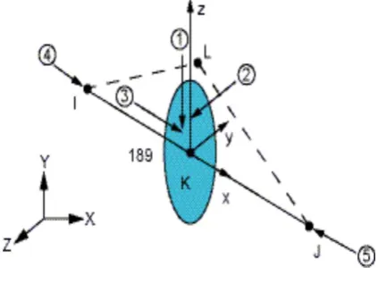
5.2 BEAM189
The BEAM189 element is suitable for analyzing slender to moderately stubby/thick beam structures. The
element is based on Timoshenko beam theory which includes shear-deformation effects. The element provides
options for unrestrained warping and restrained warping of cross-sections.The element is a quadratic three-node
beam element in 3-D. With default settings, six degrees of freedom occur at each node; these include
translations in the x, y, and z directions and rotations about the x, y, and z directions. An optional seventh degree
of freedom (warping magnitude) is available. The element is well-suited for linear, large rotation, and/or
large-strain nonlinear applications.The element includes stress stiffness terms, by default, in any analysis
with NLGEOMON. The provided stress-stiffness terms enable the elements to analyze flexural, lateral, and
torsion.Elasticity, plasticity, creep and other nonlinear material models are supported. A cross-section associated
with this element type can be a built-up section referencing more than one material.
Fig 6.Configurations of beam189 element
We then apply the MDC method to the wrinkling numerical simulation codes (ANSYS) by incorporating the
direct perturbed method and the nonlinear post-wrinkling calculation. Although the method has eliminated the
singularity of the stiffness matrix,we also use several effective strategies to advance the convergence. The first
is the introduction of the stress stiffening effect. This effect can deal with the coupling conditions between the
in-plane membrane tension and the out-of-plane wrinkle deflection. After meshing of the elements, this effect is
introduced by reducing the structural temperature. Reducing the temperature to introduce the stress stiffening
effect does not affect the computations, i.e., it does not lead to a thermal stress problem. The second is the
227 | P a g e
to substitute the force loadings. That is to say, we increase the tension displacement to generate the loading
function, which can push the wrinkling computation into the post-buckling phase smoothly.
Where, the forces in the calculation of the non-equilibrium force equation come from the nodal reaction forces
which are generated by the incremental displacements. In the end, the nonlinear equation is solved by using the
Newton–Raphson iteration and the dichotomy method. The dichotomy method is an effective auto-correction
for the failed convergence. This method will divide the time step into two halves and then restart computation
from the last convergent sub-step when the iteration is divergence. The dichotomy will end until iteration
reaches convergence. In addition, the increment of displacement loadings is limited to smaller value to satisfy
with the requirement of convergence.
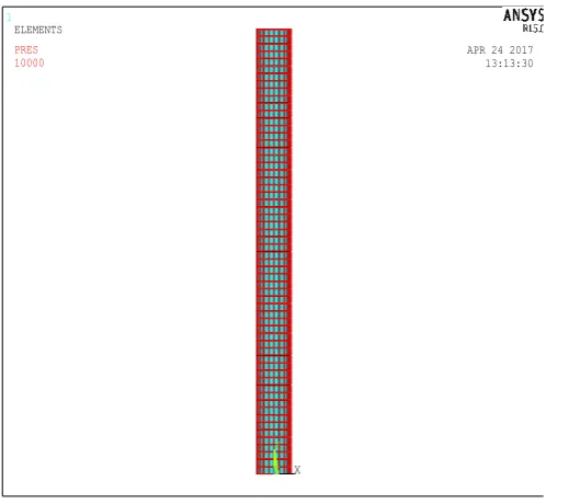
Fig 7. Meshed model of inflatable beam
VI. RESULTS AND DISCUSSION
6.1 Modal Analysis of Spindle Shaped Tensairity Beam
Modal analysis of spindle shaped tensairity beam was done by dividing the fabric material of the hull element
into three layers of same material of equal thickness but by varying the orientation of fabric in each layer.The
total thickness of the fabric is 0.5mm.For the analysis,aluminium was taken as the tension and compression
element and PVC coated polyester was chosen as the fabric material and internal pressure of 150mbar was
provided in the hull element.The first four natural frequencies are obtained for different orientation and are
shown in Table.
1
X
Y
Z
APR 24 2017 13:13:30 ELEMENTS
228 | P a g e
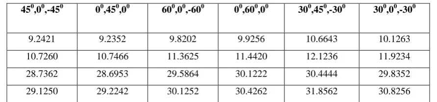
Table 1 Comparison of Frequencies for Different Orientation of Fabric
450,00,-450 00,450,00 600,00,-600 00,600,00 300,450,-300 300,00,-300
9.2421 9.2352 9.8202 9.9256 10.6643 10.1263
10.7260 10.7466 11.3625 11.4420 12.1236 11.9234
28.7362 28.6953 29.5864 30.1222 30.4444 29.8352
29.1250 29.2242 30.1252 30.4262 31.8562 30.8256
The frequencies corresponding to orientation 450,00,-450 and00 ,450 ,00 are the lowest and are found close to each
other. Considering symmetry, orientation of 00 , 450 , 00 was chosen for further analysis.
6.2 Study of Load-Displacement Characteritics of the Spindle Shaped Tensairity Beam
To study the load displacementbehaviour of a spindle shapedTensairity beam, a central loadwas introduced at
the center of the compression chordof the beam as shown in Fig 6.9. For the analysis, aluminium was taken as
the chord element and PVC coated polyester in three layers with an orientation 00,450,00 was used as the hull
element. The study was conducted for an initial load of 0.2KN and the deflection was obtained. Now by
changing the load to 0.4KN, 0.6KN, 0.8KN and 1KN, the corresponding deflections were obtained for a
pressure of 150mbar.
6.3 Load-Displacement Characteritics for Different Tension and Compression Material
The material properties of different materials used in the parametric study of tensairity beam are given in Table.
Table 2 Material Properties
Material Modulus of
elasticity(N/m2)
Density
(kg/m3)
Poisson’s ratio
Steel 210X109 7800 0.3
Copper 120X109 8940 0.35
Aluminium 69X109 2700 0.33
PVC coated polyester 4.14X10⁹ 1440 0.39
Polypropylene 1.1x10⁹ 900 0.4
Nylon 2.8X10⁹ 1120 0.34
The load deflection behaviour of the spindle shaped Tensairity beam was done with three different compression
and tension members.The three different materials used for chord material were aluminium,steel and copper.For
the analysis,PVC coated polyester in three layers with an orientation 00,450,00 was used as the hull element and
aninternal pressure of 150mbar wasused.The load displacement response of spindle shaped tensairity beamfor
229 | P a g e
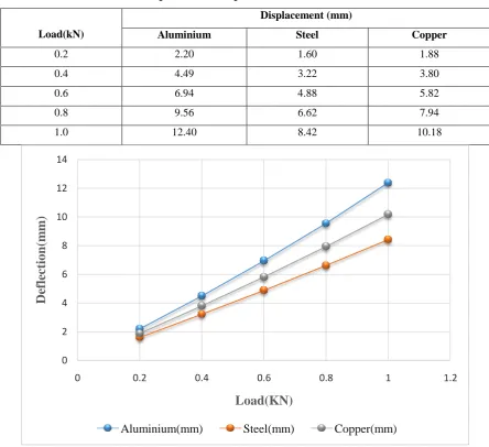
Table 3 Load Displacement Response for Different Chord Materials
Load(kN)
Displacement (mm)
Aluminium Steel Copper
0.2 2.20 1.60 1.88
0.4 4.49 3.22 3.80
0.6 6.94 4.88 5.82
0.8 9.56 6.62 7.94
1.0 12.40 8.42 10.18
Fig 8 Load-Displacement response graph for different chord materials
From above the graph,spindle shaped Tensairity beam with aluminium rod shows greater displacement than
other two material.Tensairity beam with steel rod shows minimum displacement. So spindle shape Tensairity
beam with steel rod will produce greater stiffness than aluminium and copper rods.
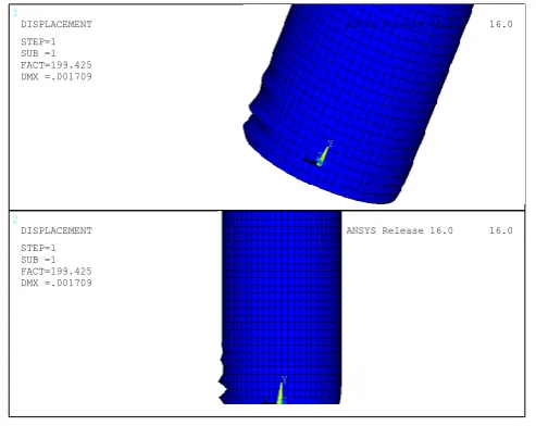
6.4 Wrinkled Patterns(Clusters)
Wrinkled patterns are the pattern obtained by the beam when subjected to localized buckling through a series of
substeps Each substep corresponds to a particular wrinkle pattern which are called clusters. 0
2 4 6 8 10 12 14
0 0.2 0.4 0.6 0.8 1 1.2
De
fl
ec
tion
(m
m
)
Load(KN)
230 | P a g e
Fig 9 wrinkled Pattern (Cluster)
VI. CONCLUSION
In this study, the static and modal analysis of spindle shaped Tensairity beam with hull element divided into
three layers of equal thickness with different orientation was done. The parametric studies of the tensairity beam
with materials,internal pressure and dimensions were done.
The important conclusions drawn from the various parametric studies are sumarised.
From the modal analysis done, it was seen that there is variation between frequencies under two different
pressures applied on the hull element. So the effect of pressure has to be taken into consideration in the
design of Tensairity beam.
Tensairity beam with chord and hull element made of low modulus of elasticity material produce higher
natural frequencies than chord element made of high modulus of elasticity material.While designing this
should be taken into account.
From modal analysis,it was found that the dimensions of tension and compression element has great
influence in designing of the beam.
The spindle shaped Tensairity beam with chord element made of low modulus of elasticity shows greater
displacement than the Tensairity beam with chord element made of high modulus of elasticity material.
Tensairity beam with hull element made of low modulus of elasticity fabric material shows greater
displacement than the Tensairity beam with hull element made of high modulus of elasticity fabric material.
Tensairity beam with low internal pressure on hull element shows greater displacement than beam with
high internal pressure on hull element. So spindle shaped Tensairity beam withhigher internal pressure will
produce greater stiffness.
REFERENCES
[1] Beyons.Thomas, Anumod.A.S (2015), “Finite element based static and dynamic analysis of tensairity spindle structure”, International Journal of Research in Engineering and Technology, vol.4, pp.97-103.
[2] Credic.Galliot, Rolf.H.Luchsinger (2013), “Structural behavior of symmetric spindle-shaped Tensairity girders with reinforced chord coupling”, Engineering Structures, vol.56, pp.407-416.
1 2 X Y Z X Y Z ANSYS Release 16.0 16.0
231 | P a g e
[3] C.Galliot, R.H.Luchsinger(2009), “A Simple model describing the non-linear biaxial tensile behaviour of
PVC- coated polyester fabrics for use in finite element analysis”, Composite Structures, vol.90, pp.
438-447.
[4] Joep.C.M. Breuer, Rolf.H.Luchsinger (2010), “Inflatable kites using the concept of Tensairity”, Aerospace
Science and Technology, vol.14, pp.557-563.
[5] Joep.Breuer, Wubbo.Ockels, Rolf.H.Luchsinger (2009), “An inflatable wing using the principle of
Tensairity”, American Institute of Aeronautics and Astronautics, vol.1, pp.1-12.
[6] K.L.Apedo, S.Ronel, E.Jacquelin, A.Bennani, M.Massenzio (2010), “Nonlinear finite element analysis of
inflatable beams made from orthotropic woven fabric”, International Journal of Solids and Structures, vol.47, pp.2017-2033.
[7] M.C. Bernasconi, G.G. Reibaldi (1985), “Inflatable, Space-Rigidized Structures: Overview of Applications & Their Technology Impact”, Paper IAF-85-210 presented at the 36th International Astronautical Congress,
Stockholm, 7-12 October, pp.455 - 465.
[8] Rolf H. Luchsinger, René.Crettol (2006), “Experimental and Numerical Study of Spindle Shaped Tensairity