88 | P a g e
DESIGN AND ANALYSIS OF A THREE FINGERED
ROBOTIC ARM
M. Arulkumar
1, V.S.Vijey
2, S.Uthish Shankar
31
Assistant Professor,
2, 3Undergraduate, Mechanical Engineering,
Sri Venkateswara College of Engineering, Chennai, Tamil Nadu, (India)
ABSTRACT
In recent years robotics arm can be employed in many grasping applications. In that fingered robotic arm can
be used widely in all applications especially in grasping. In practice, while preferring multi fingered robotic
arm, to achieve the required grasping power. This facilitate increased total weight of robots and stress
deformation in links. In present work, three fingered robotic arms can be analyzed with different materials
(stainless steel, aluminium alloy, magnesium alloy and titanium alloy) under various load conditions. The stress
analysis and deformation of links were analytically evaluated through ANSYS work bench with axial and
vertical loading condition. Influence of various material on three fingered robotic arms was discussed.
Keywords: Grasping, Loading condition, Reaction moment, Stress analysis
I. INTRODUCTION
Robots have the potential to play a large role in our world. They can be widely used many industrial application especially in case of grasping. [1] The developed prosthetic hand like that of the human hand which perform similar to the human hand. The main disadvantage of the hand is the grasping capacity and manipulator capability, the each part designed separately. The spring used to retracts after taking force. [3] In this paper the human factor is determined with the largest component, in that major application point focused on the grasping force and DOF. It concludes that study of complex process of grasping. [5] The paper based on the design of actuated prosthetic hand with 5 fingered dexterous hand. It fabricated with low cost material in order to reduce the cost. According to this paper the future work can be done on the material selection and weight of the hand. The main objective of the present study to investigate various material is used to design the three fingered robotic arm. The material can be chosen based on availability and cost factor. The fingered robotic arm can be designed with four links. Determination of stress and deformation of arms undervarious loading condition like axial and vertical load. From the results obtained the influence of various material properties under different loading condition were reported and discussed.
II.MODELLING OF ROBOTIC ARM
89 | P a g e
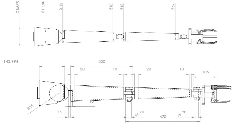
arm can be designed separately through the software. The final assembly of robotic arm in 2D view can be shown in “fig.1”.
Figure 1: Overall 2D view of Robotic arm
III.ANALYSIS OF ROBOTIC ARM
The stress analysis and deformation of various links with different material under various loading condition can be analyzed with the help of analyzing platform ANSYS Workbench. This platform is the framework unifying our industry leading suite of advanced engineering simulation technology. Through the analysis platform we can analyze individual part of the robotic by applying load on the palm. Based on different loading condition stress analysis and deformation changes according to material property changes. The values of different materials under different loading condition were tabulated and plotted. The sample output of ANSYS Workbench for
stainless steel shown in
fig.2&3”.
90 | P a g e
Figure 3: Stainless steel Deformation of link 3 and 4
IV.RESULTS AND DISCUSSION
For analyzing the three fingered robotic arm four different materials were chosen(Stainless steel, Aluminium alloy 6061 T6 , Magnesium alloy, Titanium alloy CP grade 01).There are certain loading conditions and cross sectional area are considered for the analyzing the robotic arm in “Fig.4” . The varying wall thickness for cross sectional areas of robotic arms are taken as 10mm, 15mm, 20mm and 25mm. The amount of load applying is 10kg, it is applied on the palm of the arm.
Figure 4: Conditions for Analyzing
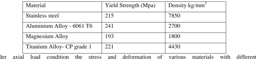
Various material properties were involved to analysis the three fingered robotic arm deformation and stress. The properties of various list in the “TABLE 1”.
Table 1: Material Properties
Material Yield Strength (Mpa) Density kg/mm3 Stainless steel 215 7850
Aluminium Alloy - 6061 T6 241 2700 Magnesium Alloy 193 1800
Titanium Alloy- CP grade 1 221 4430
91 | P a g e
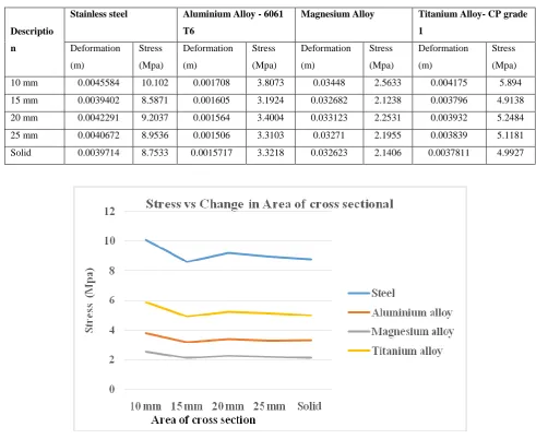
Table 2: Stress and Deformation for Axial load conditions
Descriptio n
Stainless steel Aluminium Alloy - 6061 T6
Magnesium Alloy Titanium Alloy- CP grade 1 Deformation (m) Stress (Mpa) Deformation (m) Stress (Mpa) Deformation (m) Stress (Mpa) Deformation (m) Stress (Mpa)
10 mm 0.0045584 10.102 0.001708 3.8073 0.03448 2.5633 0.004175 5.894
15 mm 0.0039402 8.5871 0.001605 3.1924 0.032682 2.1238 0.003796 4.9138
20 mm 0.0042291 9.2037 0.001564 3.4004 0.033123 2.2531 0.003932 5.2484
25 mm 0.0040672 8.9536 0.001506 3.3103 0.03271 2.1955 0.003839 5.1181
Solid 0.0039714 8.7533 0.0015717 3.3218 0.032623 2.1406 0.0037811 4.9927
Figure 5: Stress vs Change in area of cross section (Axial load)
Under axial load condition the directional deformation of various links of various materials with different description (10mm, 15mm, 20mm, 25mm and in solid section) can be obtained through analysis “TABLE 3”. The graph can be plotted between obtained directional deformation for different materials and area of cross section under different description “fig. 6 &7”
Table 3: Directional deformation under axial load condition
Descri ption
Stainless steel Aluminium Alloy - 6061 T6
Magnesium Alloy Titanium Alloy- CP grade 1
L1 L2 L3 L4 L1 L2 L3 L4 L1 L2 L3 L4 L1 L2 L3 L4
10 mm 1.42 2.26 1.00 1.21 1.40 2.26 1.01 1.24 1.44 2.37 1.07 1.31 1.69 2.71 1.19 1.45
15 mm 2.13 1.94 0.87 1.05 2.07 1.92 0.87 1.06 2.13 1.99 0.91 1.11 2.52 2.29 1.02 1.24
20 mm 2.35 2.02 0.93 1.12 2.31 1.99 0.93 1.13 2.37 2.06 0.97 1.18 2.79 2.38 1.09 1.33
25 mm 2.41 1.82 0.89 1.08 2.35 1.80 0.89 1.08 2.41 1.87 0.92 1.13 2.85 2.17 1.05 1.28
Solid 2.61 1.81 0.81 1.06 2.55 1.79 0.87 1.06 2.61 1.86 0.90 1.11 3.09 2.15 1.03 1.25
92 | P a g e
Figure 6: Directional deformation of link 1 & 2
Figure 7: Directional deformation of link 3 & 4
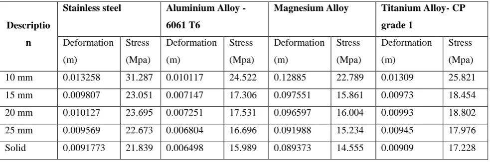
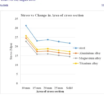
Under vertical load condition the stress and deformation of various materials with different description(10mm,15mm,20mm,25mm and in solid section) can be obtained through analysis “TABLE 4”. The
graph can be plotted between obtained stress values for different materials and area of cross section under different description “fig. 8”
Table 4: Stress and Deformation for vertical load conditions
Descriptio
n
Stainless steel Aluminium Alloy -
6061 T6
Magnesium Alloy Titanium Alloy- CP
grade 1
Deformation (m)
Stress (Mpa)
Deformation (m)
Stress (Mpa)
Deformation (m)
Stress (Mpa)
Deformation (m)
Stress (Mpa)
10 mm 0.013258 31.287 0.010117 24.522 0.12885 22.789 0.01309 25.821 15 mm 0.009807 23.051 0.007147 17.306 0.097551 15.861 0.00973 18.454
20 mm 0.010127 23.695 0.007251 17.531 0.096597 16.004 0.00993 18.802
93 | P a g e
Figure 8: Stress vs Change in area of cross section (Vertical load)
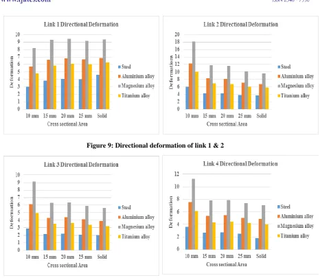
Under vertical load condition the directional deformation of various links of various materials with different description (10mm, 15mm, 20mm, 25mm and in solid section) can be obtained through analysis “TABLE 5”.
The graph can be plotted between obtained directional deformation for different materials and area of cross section under different description “fig. 9 &10”
Table 5: Directional deformation under vertical load condition
Descri ption
Stainless steel Aluminium Alloy – 6061 T6
Magnesium Alloy Titanium Alloy- CP grade 1
L1 L2 L3 L4 L1 L2 L3 L4 L1 L2 L3 L4 L1 L2 L3 L4
10 mm 3.01 5.98 2.91 3.57 5.69 12.3 6.15 7.60 8.16 18.15 9.10 11.25 4.82 10.07 4.94 6.08
15 mm 3.82 4.29 2.16 2.66 6.65 8.26 4.33 5.36 9.30 11.89 6.29 7.81 5.87 6.91 3.53 4.36
20 mm 4.03 4.28 2.21 2.72 6.83 8.09 4.38 5.42 9.47 11.58 6.34 7.87 6.11 6.82 3.59 4.44
25 mm 4.01 3.79 2.08 2.57 6.68 7.10 4.08 5.08 9.19 10.15 5.91 7.37 6.01 6.03 3.37 4.18
Solid 4.60 3.66 2.00 1.80 6.85 6.79 3.90 4.85 9.34 9.68 5.62 7.02 6.23 5.81 3.22 4.00
94 | P a g e
Figure 9: Directional deformation of link 1 & 2
Figure 10: Directional deformation of link 3 & 4
V. CONCLUSION
Inference of above result are stress and deformation decreases with increasing area of cross section of the links. In case of axial load conditions Mg alloy shows less range of stress values varying from 2.560 to 2.14 Mpa. But in vertical load condition all four materials shows similar range of stress values. In directional deformation links, the link 1 have more deformation when compared to other links in axial load conditions. But link 4 shows higher deformation in vertical load conditions. According to various load condition, directional deformation of links Mg alloy shows better result when compared to other materials (Stainless steel, Aluminium alloy and Titanium alloy).
REFERENCE
[1] M Thompson, Design and fabrication of prosthetic hand, International Journal of mechanical and industrial Technology ISSN 2348-7593, vol.2,Issue 1,April2014-September 2014
95 | P a g e
[3] Daniela Tarnita, Analysis of a hand arm system, Elsevier Robotics and Computer-integrated manufacturing 29(2013)493-501.
[4] Ankit Gupta, Efficient Design and Implementation of 4 Degree of Freedom robotic Arm, International Journal of Engineering and Advanced Technology,ISSN:2249-8958,Vol.2,Issue5(2013).
[5] Umar Farooq, Mechanical Design of a Tendon Activated Prosthetic Hand, 2012 IEEE International Conference on Robotics.