Temperature Analysis for Designing a New
High-Powered Strontium Bromide Laser
Iliycho Petkov Iliev
Abstract: - In this paper a complete thermal model of the radial heat flow for a high-powered He-SrBr2 laser is obtained. The model is based on a general analytic solution of the steady-state heat conduction equation subject to mixed boundary conditions for the arbitrary form of the volume power density in the internal laser tube, combined with nonlinear boundary value conditions in the rest part of the composite tube. The model does not require experimental values of the wall temperatures. It is applied for designing of a new high-powered SrBr2 laser. The influence of the diameter of the outer insulation and the heat conductivity coefficient of the medium between the two tubes at maintenance of the optimal gas temperature is investigated.
Index Terms: - Analytical model, free convection, heat conduction, gas temperature, radial heat flow, SrBr2 laser, strontium bromide laser, vapour laser.
————————————————————
1 I
NTRODUCTIONTHE strontium bromide (SrBr2) vapour laser is among the
latest inventions in this field. Stable laser generation was achieved for the first time in 2002 [1]. The new device is based on a strontium vapour laser with atomic strontium replaced by strontium bromide. One of the important prospects for this laser is connected with its radiation at 6.45 m, which as shown in [2, 3], is the most effective means for soft tissue and bone ablation with minimum thermal damage and pollution during operations. For this reason, the Strontium bromide laser is replacing currently used free electron lasers due to its superior technical characteristics, price, and considerably easier maintenance in various kinetic systems. The SrBr2
vapour laser significantly outperforms the atomic strontium laser due to the longer service life of its laser tube [4, 5]. All these advantages make the SrBr2 vapour laser commercially
viable and the object of active development. Up until now, laser generation with output power 4.26 W has been achieved, with 90% of generation on the line = 6.5 m [6-9]. The operating temperature of SrBr2 vapour lasers is 1000
оС. This
sets special requirements when constructing new laser sources of this type. In order to design a new SrBr2 vapour
laser (with expected output power of 6-7 W), it is necessary to pre-evaluate the possible temperature mode of the active laser medium and the laser tube so as to determine the optimal operating temperature. The obtained results are part of the general preliminary research on the new SrBr2 vapour laser.
The electric power supply, the optical resonator, and the mechanical structure will be evaluated and statistical methods will be used to predict the laser generation. The optimal temperature profile of the future device needs to be determined only in the context of the general analysis. The currently developed temperature model [10, 11] allows us to determine the temperature profile of the existing laser [6-9]. This model has been developed for a known temperature of the outer quartz wall, under the heat insulation, obtained by precise measurement.
When designing new laser sources, this temperature remains unknown. This means the model cannot be applied. The need arises for a new temperature model, which would not require the preliminary input of the temperature in question, but rather allows for it to be obtained as a result of the complex thermal interactions between the outside surface of the laser tube and the external environment. This is the aim of this paper.
2
D
ESCRIPTION OF THEN
EWT
EMPERATUREM
ODEL2.1 Mathematical formulation
In line with [10, 11], the following heat conduction equation in cylindrical coordinates needs to be solved inside the ceramic tube (see Fig.1):
div grad(Tg) qv 0 (1)
where is the thermal conductivity coefficient of the gas,
0
m g T
, 0 0.0027, m0.7057, qv is the volume power density of the internal heat source, and Tg is the temperature
of the gas. In order to simplify, equation (1) is considered under the first and second type boundary conditions:
1 1 1 1
( ) , 0.5
g
T R T R d (2)
0
0 g
r dT
dr (3)
The boundary condition (2) reflects the fact that the temperature Т1 on the inside wall of the ceramic tube (see Fig.
1) is known, and the boundary condition (3) shows that due to the symmetry of the temperature in relation to the centre of the tube (r0), the first derivative is zero. We will consider the following mixed boundary conditions for the actual solution of equation (1) for the geometric design shown in Fig. 1:
Condition A. We preset an external surrounding temperature
air
T 300K. In order to determine the unknown temperatures
4
T and T5 we use new boundary conditions as follows ————————————————
4
4 5 5 air 5 5/100 air/100QF T T F c T T (4)
4 5 lln 5 4 / 2 4
T T q d d (5)
Boundary condition (4) describes the heat exchange between the outside surface of the laser tube and the surrounding medium. It contains two terms. The first term is derived from the Newton’s law for heat exchange through convection, and the second from the Stefan-Boltzmann law for heat exchange through radiation. The quantity Q is the total heat flux, equal to the effective electric power Q =1365 W consumed by the tube,
is the heat transfer coefficient, F5 is the outside active surface of the insulation of the tube, is the integral radiation coefficient, dependent on the material, 2 4
5.67 W /(m K )
c -
radiation coefficient. There are two unknown quantities in boundary condition (4) - and T5. In order to determine T5, it is first necessary to determine the heat transfer coefficient .
Condition B. The following equation is true for the quartz tube (in cylindrical configuration) [9]:
3 4 lln( 4 3) / 2 3
T T q d d (6)
Condition C. The space between the two tubes (Fig. 1,
position 3), is filled with helium. The boundary condition is in the following form:
4 4
2 3 2
2
2 3 2 3
3 2 3 2
/100 /100
2 2
ln ln
eff
eff a a
Q c T T S
l l
T T T T
d d d d
(7)
or Q = Q1+Q2+Q3, where:
1
11 2 1 3 23 2 2
1 /( ) 1 /
eff S S F
1 4
*
1 42
0.386 Pr/(0.861 Pr)
eff Racyl
*
1 4
3 4
3 5 3 5
5 4 1 43 2 2 3
ln cyl
Ra d d
d d Ra
3 2
2 3 Pr / , 0.5 3 2
Rag T T d d
Boundary conditions (6) and (7) take into account the process of heat transfer through heat conduction. In boundary conditions (7), the first summand Q1 represents the Stefan–
Boltzmann law and describes the heat exchange by radiation of the ceramic tube in an enclosed space (Fig. 1—(2)), Q2 stands for Newton’s law and describes the process of heat conduction. The third summand Q3 in (7) describes the free convection in an enclosed space (Fig. 1—(3)). In this way, boundary condition (7) takes into account all possible processes of heat transfer: radiation, heat conduction, and free convection.
Condition D. Equation for the wall temperatures of the
ceramic tube is
1 2 lln 2 1 / 2 1
T T q d d (8)
The assigned notations in the above conditions are as follows: The quantity Q =1365 W is the heat flux, equal to the consumed electric power, qlQ l/ ,a la 1m - active length,
1, 2, 3, 4
are respectively the heat conductivity coefficients of the Al2O3 tube, helium between the tubes, the quartz tube
and the heat insulation, dj, j=1,2,…,5 are the diameters of
constituent tubes, c is the radiation coefficient. The quantity
eff
is the effective radiation coefficient, taking into account the multiple reflections in the space between the two tubes (position 3), Fig.1, 1 0.52 and 2 0.72 are respectively the integral radiation constants of the ceramic and the quartz tube, S2l da 2 and S3l da 3 are the surface areas. Thequantity F230.8 is a geometric factor. Its value is determined
by the ratios d2/d3 and la/d2, Pr0.6. Coefficients
, are determined in [11].2.2 Determination of the natural convection heat transfer coefficient
The Nusselt criterion Nu is used to determine , regardless of the type of convection [12]
NuH/ (9)
2 1 3 4
T0
d1
T5
d2
d3
d4
d5
T4
T3
T2
T1
1 2 3 4 5
Fig. 1. Geometrical design of the cross-section of the
laser tube of a new He-SrBr2 laser: 1 – discharge, 2 –
ceramic (Al2O3) tube, 3 – space filled with helium or
other material, 4 –quartz tube and 5 – insulation. The diameters are as follows: d130.5mm, d238.6mm,
371mm
Grashoff's criterion Gr is applicable for free convection [12]
3 2
5
Grg H T Tair / (10)
The following relationship between the two criteria is valid for horizontal tubes with natural convection [13]:
0.25
Nu0.46Gr (11)
The last equation is true for 7
700Gr7.10 . The quantities used in (9)-(11) are: H - characteristic body size, here
5
H d , g- standard earth gravity, - thermal coefficient of gas volume expansion, - kinematic viscosity, - thermal conductivity coefficient. For the air
3 1
3, 41.10 K air
, 15, 7.10 6m /s2air
,
0, 0251W/ mK air .
These data are valid for air temperature 300K [13]. Through (9)-(11), the quantity assumes the form
0.253 2
5 5 0 5
0.46 air g aird T T / air /d
(12)By using (12), boundary condition (4), expressed by the power per unit length, becomes
0.25
3 2
5 5 5
4 4
5 5
0.46
/100 /100
l air air air air air
air
q g d T T T T
d c T T
(13)
The only unknown quantity in equation (13) is T5. After
defining it through (4), (6), (7) and (8), T T T4, 3, 2 and T1, are found in succession.
2.3 Determination of the temperature in the cross-section of the active volume
The temperature profile of the radial heat flow in the cross-section of the laser volume can be determined when the temperature T1 is known. The general solution of (1) is represented by the expression [14, 11]
1 1/ 1 ln1 1 2
1 0 ln
( ) 1 ( )
m r
m
g R v
T r T m d e q e d
(14)Using qualitative type of distribution for qv q rv( ) in long gas discharge (see for instance [15], Chapter 6 or [16] for the case of copper vapour lasers), we can take the representation [10]
2
1 0v
q r K q a br (15)
where K11.43424, a1.0237072, b-9993.0943, and
0 /
q Q V is the average volume power density, V is the volume of the active zone. The obtained distribution of the temperature is [10]:
1 1 2 2
1 0 1 0 1
1/ 1 2 2
1
( ) 1 /16
4 m g
m
T r T m K q r R
a br bR
(16)
3 R
ESULTS FROM THE APPLICATION OF THE NEW MODELThe geometric dimensions of the new laser source are given in Fig.1, where the diameter of the outer insulation d5 has to
be specified. It has the same active zone length la 1m
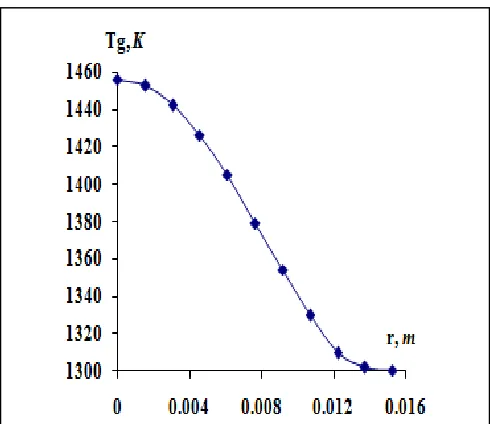
(la 0.98m for the preceding laser), but its transverse dimensions are larger. The power supply is the same – total electric power supplied 2.1KW. Preliminary analyses show that the longitudinal value of the intensity of the electric field (EL Uel/la) remains practically the same due to the equal distances between the electrodes of the two lasers. Thus it is accepted that laser gain would remain the same because it is proportional to EL. The volume of the new laser source is increased significantly (V 730 cm3) compared to the old volume of (V 300 cm3). The increased outside surface area would boost cooling and although the supplied electric power would remain the same, the temperature in the active medium would be lower than the optimum. This places doubt on the effectiveness of the operation of the new laser source. For this reason, the development of the new temperature model is a means to find constructive solutions with the goal of increasing gas temperature to the previously determined optimal value. Fig. 2 shows the calculated distribution of the gas temperature when d5. It is determined using an approximation of qvof type
Fig. 3 shows some results of computer simulations of these relationships with the help of which the necessary optimal temperature T01588K [11] in the centre of the discharge is achieved. The analysis of the results in Fig. 3 shows that the thickness of the outer insulation exerts a stronger influence on the maintained optimal temperature T0 in the tube than the heat conductivity coefficient of the new material. Our opinion, in accordance with this figure, is that it is sensible to choose a material with *0.7 W/(mK), with the correction of the temperature of the active medium achieved by changing the thickness of the outside insulation. Knowing the heat conductivity coefficient of the unknown material at a hypothetical temperature of about 1200K poses a new problem in finding such type of material. It needs to be heat resistant at this temperature, not to break down thermo-chemically, not to pollute the laser tube, and not to change its thermo-technical properties with time. It may be necessary to develop a specially-designed composite material, consisting of various insulation materials. This poses a new problem, which is to be solved - measuring an unknown heat conductivity coefficient of a material at temperatures between 1000-1500K. The question about determining the optimal temperature of the laser medium also remains open. The temperature at the centre of the tube cannot be measured reliably. Its optimal value can only be determined by the operation of the laser source. The optimal temperature and respectively thickness of the outer insulation is that, at which the laser source generates high output power and demonstrates operational stability with time.
4 C
ONCLUSIONA complete temperature model has been developed and applied in designing a project of a new SrBr2 laser source. The
advantage of this model is that it allows us to determine the temperature profile in the laser tube without inputting the temperature of the outer tube, which is often unknown for new sources. Computer simulations have been carried out with the goal of defining the conditions needed to obtain the optimal temperature profile.
R
EFERENCES[1] B.L. Pan, Z.X. Yao and G. Chen, “A discharge –excited SrBr2 vapour laser,” Chin. Phys. Lett., vol. 19, no. 7, pp.
941-943, 2002.
[2] G.M. Peavy, L. Reinisch, G.T. Rayne, and V. Venugopalan, “Comparison of cortical bone ablations by using infrared laser wavelength 2.9 to 9.2 μm, “ Laser Surg. Med., vol. 25, pp. 421-434, 1999.
[3] J.M. Auerhammer, R. Walker, A.F.G. van der Meer, and B. Jean, “Dynamic behavior of photoablation products of corneal tissue in the mid-IR: a study with FELIX,” Appl. Phys. B- Lasers Opt., vol. 68, pp. 111-119, 1999.
[4] A.V. Platonov, A.N. Soldatov, and A.G. Filonov, “Pulsed Strontium Vapor Laser,” Sov. J. Quantum Electon., vol. 8, pp. 120-121, 1978.
[5] A.N. Soldatov, A.G. Filonov, A.S. Shumeiko, A.E. Kirilov, B. Ivanov, R. Haglund, M. Mendenhall, B. Gabella, and I. Kostadinov, “A Sealed-Off Strontium Vapor Laser,” in: Atomic and Molecular Pulsed Lasers V, V.F. Tarasenko, Ed., Proc. of SPIE, vol. 5483, pp. 252-261, 2004.
[6] K.A. Temelkov, N.K. Vuchkov, B.L. Pan, N.V. Sabotinov, B. Ivanov, and L. Lyutov, “Strontium atom laser excited by nanosecond pulsed longitudinal He-SrBr2 discharge,” J. Fig. 2. Distribution of the gas temperature obtained by
the model (1)-(5) and formula (13).
Fig. 3. Dependence between the insulation diameter
5
Phys. D: Appl. Phys., vol. 39, pp. 3769-3772, 2006.
[7] K.A. Temelkov, N.K. Vuchkov, B.L. Pan, N.V. Sabotinov, B. Ivanov, and L. Lyutov, “Strontium bromide vapor laser excited by a nanosecond pulsed longitudinal discharge,” Proc. 14th International School on Quantum Electronics: Laser Physics and Applications, P.A. Atanasov, T.N. Dreischuh, S.V. Gateva,and L.M. Kovachev, Eds., Proc. of SPIE, vol. 6604, pp. 660410-1, 2007.
[8] K.A. Temelkov, N.K. Vuchkov, I. Freijo-Martin, A. Lema, L. Lyutov, and N.V. Sabotinov, “Experimental study on the spectral and spatial characteristics of a high-power He-SrBr2 laser,” J. Phys. D: Appl. Phys., vol. 42, no. 115105,
pp. 1-6, 2009.
[9] K.A. Temelkov, N.K. Vuchkov, B. Mao, E.P. Atanasov, L. Lyutov, and N.V. Sabotinov, ”High-power Sr atom laser excited in nanosecond pulsed longitudinal He-SrBr2 discharge,” IEEE J. Quant. Electron., vol. 45, no. 3, pp. 278-281, 2009.
[10]I.P. Iliev, S.G. Gocheva-Ilieva, K.A. Temelkov, N.K. Vuchkov, and N.V. Sabotinov, “Analytical model of temperature profile for a He-SrBr2 laser, Optoelectron.
Adv. Mater., vol. 11, no 11, pp. 1735-1742, 2009.
[11]I.P. Iliev, S.G. Gocheva-Ilieva, K.A. Temelkov, N.K. Vuchkov, and, N.V. Sabotinov, “An improved radial temperature model of a high-powered He-SrBr2 laser,” Opt. Laser Technol., vol. 43, pp. 642-647, 2011.
[12]M.N. Özişik, Heat Transfer. A Basic Approach, Boston: McGraw-Hill, 1985.
[13]Tables of Physical Quantities, I.K. Kikoin, Ed., Moscow: Atomizdat, 1976 (in Russian).
[14]I.P. Iliev, and S.G. Gocheva-Ilieva, “Model of the radial gas temperature distribution in a copper bromide vapour laser,” Quantum. Electron., vol. 40, pp. 479-483, 2010.
[15]J.F. Waymouth, Electric discharge lamps, Cambridge, Massachusetts and London: The M.I.T. Press, 1971.