23
Implementation Of RS Decoder Using High-Speed
UHD Architecture
Bhashipaka. Ashok, M. A. Himayath Shamshi
Abstract: Reed-Solomon (RS) codes are widely used as f orward correction codes (FEC) in digital com munication and storage systems.correcting ran random errors of RS codes have been extensiv ely studied in both academia and industry. Ho wever, for burst-error correction, the research is still quite limited due to its ultra high compu tation complexity. In this brief, starting from a recent theoretical work, a low-complexity refo rmulated inversionless burst-error correcting (RiBC) algorithm is developed for practical ap plications.Then, based on the proposed algorit hm, a unified VLSI architecture that is capabl e of correcting burst errors, as well as random errors and erasures, is firstly presented for mu lti-mode decoding requirements. This new arc hitecture is denoted as unified hybrid decoding (UHD)architecture. It will be shown that,being the first RS decoder owning enhanced burst er ror correcting capability, it can achieve signifi cantly improved error correcting capability th an traditional hard-decision decoding (HDD) design. A design of (7, 3) Reed Solomon encod er and Decoder are implemented using VHDL hardware description language (HDL) code, sim ulated and synthesized by XILINX ISE simulator.
General Terms : Burst errors, Reed-Solomon codes,RiBC algorith m and UHD architecture.
Keywords : Burst error correction, Hard decision decoding,u nified VLSI architecture.
————————————————————
I.Introduction
Reed-Solomon (RS) codes have been widely emp loyed for error correction in modern digital comm unication and data storage systems. Similar with other forward correction codes (FEC), when usin g RS codes as channel coding, the errors occurred in transmission procedure are typically divided in to random errors and burst errors. During transmi ssion error may happen for a number of reasons e.g. (scratches on CD, radio frequency interferen ce with mobile phone reception, noise etc.) At th e receiving side, the decoder detects and correct s limited predetermined number of errors occure d during transmission.a low-complexity high spe ed RS encoding and decoding architecture will im prove the overall system performance significant ly. In this a low complexity reformulated inverse free burst-error correcting (RiBC) algorithm is de veloped for practical applications. In this brief,de veloped from the above new algorithm, a high sp eed reformulated inversionless burst-error correct ing (RiBC) algorithm is proposed, and a unified h ybrid decoding (UHD) architecture that supports t hree decoding modes is presented for the first tim e. It will be shown that, compared with traditional RS decoder, the proposed UHD architecture can a chieve significantly better burst-error correcting capability. In this paper, basics of galois field theory and are a efficient RS encoder in section II. Proposed Re formulated Inversionless-free Burst-Error correcti ng (RiBC) Algorithm explained in section III,RS d ecoder using UHD architecture are implemente d in SectionIV, and Section V covers the Hardwar e performance and Experimental results are sho wing the simulation results of proposed design. Final conclusion is drawn in Section VI.
II. GALOIS FIELD
Galois field theory plays main role in the Reed S olomon Encoding and Decoding process . A Galo is field consist of set of elements(numbers).The el ements are based on a primitive element ,usually denoted as α and take the values ,
(0, 1, α, α2,..., αN-1
)
to form a set of 2m elements,where N =2m-1. field is then known as GF(2m) . the value of α is usually choosing to be 2.The Reed-Solomon code is defined in the Galois field which contains a finite set of elements where any arithmetic oper ations on elements goes on such elements belon ging to the same set. Burst errors are efficiently c orrected by using cyclic codes. The Galois field or the Finite Fields are extensively used in the Err or -Correcting Codes (ECC) . In this section these finite fields are discussed . The Galois Field is a f inite set of elements which has defined rules for a rithmetic. These roots are not algebraically differ ent from those used in the arithmetic with ordinar y numbers but the only difference is that there is only a finite set of elements involved. They have been extensively used in Digital SignalProcessing (DSP), Pseudo- Random Number Generation, En cryption and Decryption protocols in cryptograph y. A Finite Field is a field with a finite field order (i.e., number of elements), a lso called a Galois field. The order of a limited field is always a prim e or a power of a prime. For every prime power,t here exists exactly one finite field GF (pm).A Fie ld is said to be infinite if it consists of infinite nu mbers .The finite field or GF contains (2m −1) non zero elements. All finite fields contain a zero element and an element, called a generator or pri mitive element α, such that every non-zero eleme nt in the field can be expressed as a power of this element. Encoders and decoders for linear block codes over GF (2m), such as Reed- Solomon code s, require arithmetic operations in GF (2m). In GF (2m) addition and subtraction are simply bitw ise exclusive-or. Multiplication can be performed by several approaches, including bit serial, bit pa rallel (combinational), and software. Division requires the reciprocal of the divisor, which can be computed in hardware using several methods, including Euclid’s algorithm, lookup tables, expo nentiation,
____________________
Bhashipaka. Ashok, M. A. Himayath Shamshi M.Tech VLSI System Design,
[email protected], [email protected]
Assistant Professor(Sr.),ECE, Electronics and
Communications Department, Vaagdevi College of
24
and subfield representations. With the exception of division, combinational circuits for Galois field arithmetic are straightforward.Fortun ately, most decoding algorithms can be modified . In GF(2m) fields, there is always a primitive ele ment α , such that you can express every element of GF(2m) except zero as a power of α . You can generate ever field GF(2m) using a primitive poly nomial over GF(2m) field is modulo arithmetic. The simplest example of afinite field is thebinary field.
Properties of Galois Field
The main properties of a Galois fields are:
A finite field or galois field must be based on a prime number to ensure t hat each row and column of its addition and multiplication tables contains uni que values.
The primitive (root) of the field is used to derive all of the values in the field.
A finite field or galois field is indeed finite, but the field repeats an infinite number of times.
The modulus of the field determines the values of its elements.
Only addition and multiplication are required subtraction and division are performed using the ad
ditive and multiplicative inverses respectively.
All elements of GF are defined on two oper operations, called addition and multiplication.
The result of adding or multiplying two elem ents from the Galois field mustbe an element in the Galois field.
Identity of addition ―zero‖ must be exist,suc h that a
+ 0 = a for anyelement a in the field.
Identity of multiplication ―one‖ must be exist such that a * 1 = a for any element a in the field.
For every element a in the Galois field,there is an inverse of addition element b such that a+b = 0. This allows the operation of substra subtraction to be defined as addition of the inverse.
For every non-zero element b in the Galois field, there is an inverse of multiplication ele ment b -1 such that bb -1 = 1. this allows the operation of division to be defined as multipl ication by the inverse.
Both addition and multiplication operations should satisfy the commutative, associative, and distributive law.
REED SOLOMON ENCODING
2.1 Reed- Solomon codes
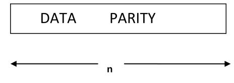
Reed-Solomon code is a block code and can be specified as RS (n, k) as shown in Fig 1.T he variable n is the size of the code word w ith the unit of symbols, k is the number of data symbols and 2t is the number of parity symbols. Each symbol consists of m numb er of bits. Reed Solomon cod es works on Ga lois field.
n - k = 2t
is the number of parity symbols.
The relation between symbol size m , and code size n is given by
n = 2m-1,
The Reed Solomon code allows correct up to t number of symbol errors.Where t is given by
t = (n-k)/2.
Where t is the symbol-error correcting capa bility of the code,
K 2t
n
Fig 1 : The structure of RS Codeword .
2.2Reed-Solomon Encoder
Reed-Solomon codes operate on the information by dividing the message stream into blocks of da ta, adding redundancy per block, dependent only on the current inputs. The symbols in Reed Solo mon coding are elements of a Galois Field (finite field). Encoding procedure is done by dividing th e message polynomial by generator polynomial, then it gives the Galois field remainder. The Galoi s field remainder is appended to the message[1]. This division is do ne by a Linear Feedback Shift Register (LFSR) implementation. Reed-Solomon Encoder using LFSR are shown in the Fig 2. The Linear Feedback Shift Register is the main compu tational element of the Reed- Solomon Encoder. The RS encoding procedure is based on Finite fiel d operations. The generating polynomial for an RS code takes the form.
φ(x) = Ξ(α1x) = 1+ φ
1x +…….…....+
φ2t-2β x2t-2β .
Fig 2 : The structure of RS Encoder.
III. Proposed Reformulated Inverse-free
Burst-Error Correcting (RiBC) Algorithm
A.Original Burst - Error Correcting (BC) Algorithm
Wu proposed a new approach to track theposition of burst of errors. By introducing a new polynomi al that is a special linear function of syndromes, Wu proved that the desired single burst of errorscan be acquired by tracking the longest consecuti ve roots of new polynomial. Furthermore, that
25
approach was extended to BC algorithm for corre cting a long burst of errors with length up to 2t-1-2β plus amaximum of β random errors. In the BC algorithm, β is a pre-chosen paramet er that determines the specific error correcting ca pability. It indicates the decoder is capable of correcting a f-length (f<(2t-2β)) burst of errors plus a maximum of β random errors. In this cas e, the miscorrection probability is upper bounded by (n-2f)(n-f)β2m(β+f-2t) .Although BC algorithm has reduced computation complexity, some disad vantages impedes its efficient VLSI design: 1) the inversion oper-ation exists , computation and con tains long data path and data dependency for calc ulating extra cycles or another copy of original circuitry are required.
B. Proposed Reformulated Inversionle- ss Burst-Error Correcting (RiBC)
Algorithm.
In the original burst error correcting algorithm consists of inversion operation and some comput ational steps contains long data dependency and long data path. To resolve these problems by app lying a similar arithmetic transformation presente d , we reformulate BC algorithm to the proposed reformulated inverse free b urst error correction algorithm(RiBC). The (RiBC) i.e,, Reformulated inverse free bur st error correction algorithm is a kind of list deco ding algorithm. In this proposed RiBC algorithm eight polynomials are updated simultaneously in each iteration. After every 2β
inner iterations, Ʌ῀(2β)
(x), as the candidate of the error locator polynomial of the random errors is computed for current lth outer iteration. When l reaches n, we track the Ʌ῀(2β)(x), that is identical for longest con secutive l, and record the last element l* of the co nsecutive l’s. Then the corresponding Ʌ(2β)(x) a nd Ʌ῀(2β)
(x) at the l*-th loop are marked as overa ll error locator polynomial Ʌ*(x) and *(
z) and error evaluator polynomial
(z) respectively . Finally Forney algorithm is used to calculate the error value in each error position with the miscorr ection probability up to (n-2f)(n-f)β2m(β+f-2t) . The proposed RiBC algorithm is targeted for correcti ng burst error plus some random errors. If the cha nnel condition guarantees that only single long bu rst of errors occurs, Wu [6] presented a low comp lexity single long burst of errors correcting (sLBC) algorithm for that case. The (sLBC) algo rithm is a special version of RiBC algorithm, and its miscorrection probability is upper bounded by )(n-2f)2m(f-2t) . In next section, a unified hybrid decoding archite architecture that can implement RiBC, sLBC and classical random errors and erasures correcting (rEEC) algorithm [2] will be presented. Hence at the end of this section, for reader’s convenience, we introduce the rEEC algorithm. In next section, a unified hybrid decoding architecture that can implement RiBC, sLBC and classical random err ors and erasures cor-recting (rEEC) algorithm [2] will be presented.
Algorithm for Reformulated Inverse - free Burst-Error Correction(RiBC)
A1: Compute
A2: For l=0 step 1 until n-1 do
f-lenth (f<2t-2β) burst of errors plus aximum β random errors :
input :syndromes s0,s1,s2,...,s2t-1 ; B1: compute Ξ(x) = (1-α1-(2t-2β)x)(1-α2-(2t-2β)x )...
(1-α-1x)(1-X).
= 1+ξ1x+ξ2x 2
+...+ξ2t-2βx2t-2β:
B2 : For l=0 step 1 until n-1 do B2.1: compute
Φ(x)=Ξ(α1x)=1+Φ 1x+Φ2x
2
+...
+ Φ2t-2βx2t-2β;
B2.2: compute Ψ(x)=ψ0+ψ1x+ψ2x 2
+...+ψ2t-1x 2t-1
, wher ψi = 𝛷
2𝑡−2𝛽
𝑗 =0 jSi+2t-2β-j;
B2.3: Initialize Ʌ(0) (x)=λ0 (0) +λ1 (0) x+...+λ2t-2 (0)
x2t-2 = Φ(x); B(0)(x)= b0
(0)
+b1 (0)
x+...+b2t-2 (0)
x2t-2 = Φ(x); Ʌ᷈(0)(x)= λ
0 ᷈(0)+λ 1 ᷈(0)+...+λ 2t-2 ᷈(0)
x2t-2=1; B᷈(0)(x)= b0᷈(0)+b1᷈(0)x+...+b2t-2᷈(0)x
2t-2
=1; Δ᷈(0)(x)= δ
0 ᷈(0)+δ 1 ᷈(0)x+...+δ 2t-1 ᷈(0)
x2t-1= Ψ(x); Ɵ᷈(0)(x)= θ
0 ᷈(0)+θ 1 ᷈(0)x+...+θ 2t-1 ᷈(0)
x2t-1= Ψ(x); Δ᷈*(0)(x)= δ0
᷈*(0)+δ 1
᷈*(0)x+...+δ 2t-1
᷈*(0) x2t-1
= S(x); Ɵ᷈*(0)(x)= θ 0 ᷈*(0)+θ 1 ᷈*(0)x+...+θ 2t-1 ᷈*(0) x2t-1
= S(x); γ(0)
=1, k(0)=0;
B2.4: for r=0 step 1 Until 2β-1 do B2.4.1: compute δ1᷈(r+1)= γ
(r)
δi+1᷈(r )- δ0᷈(r)θ1᷈(r);
δi
᷈*(r+1)= γ(r)δ i+1
᷈*(r) - δ 0 ᷈(r)θ 1 ᷈*(r) ; λi
᷈(r+1)= γ(r)λ i
(r) – δ 0 ᷈(r) bi-1 (r) ; λi
᷈(r+1)= γ(r)
λi ᷈(r) – δ
0 ᷈(r)
bi-1 ᷈(r)
;
B2.4.2: if δ0᷈(r) ≠ 0 and k (r)
≥ 0 then a=1; else a=0;
bi
(r+1) λ i
(r) b i-1
(r)
a
bi᷈(r+1) λi᷈(r) bi-1᷈(r)
θi
᷈(r+1) δ i+1
᷈(r) θ i
᷈*(r)
θi
᷈*(r+1) = δ i+1
᷈*(r) θ i
᷈*(r)
γ(r+1) δ 0
᷈(r) γ(r)
k(r+1) -k(r) -1 k(r)+1 ā
B3: Track the longest consecutive Ʌ᷈(2β)
(x) th- at are identical, recorded the last element l* of the consecutive l’s , then the overall err- or locator polynomial Ʌ*(x) = Ʌ(2β)(x) at the l’th outer loop. The overall evaluator polynomial Ὡ(x) is cor- responding Δ᷈(2β)(x) at the l’th outer loop .
OUTPUT : Ʌ*
(x), Ὡ*
(x).
IV.
Proposed
Unified
Hybrid
Decoding
Architecture.
com-26
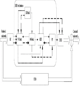
putation steps. Based on this interesting similarity, a unified hybrid de-coding (UHD) architecture that is capable of correcting these three dif-ferent types of errors pattern (or called as three work modes) will be given in this section. Fig. 3 shows the overall architecture of UHD decoder.Three types of lines illustrate data flows for different work modes: solid line for mode-1, dashed line for mode-2 and dotted line for mode-3. Different blocks are used to process different steps. Since SC and CSEE block have been dissc ussed in previous literatures, their architectures are not discussed in this brief. The above three algorithms are share many simil lar computation steps. Based on this interesting si milarity, a UHD architecture is designed. Figure 3 shows the overall architecture of Unified Hybri d Decoding decoder. Three types of lines illustrat tes the data flows for different work modes: solid line for mode-1 for burst combined with random error correction RiBC algorithm, dashed line for mode-2 for only burst error correction and big da shed line for mode-3 for only random error correc tion. Different blocks are used to process differen t steps in the algorithm.
Fig.3: Overall architecture of proposed UHD decoder.
PROPOSED UNIFIED HYBRID DE- CODING
ARCHITECTURE.
The proposed RiBC algorithm is very effective for correcting combination of burst errors and random errors (mode-1), while sLBC and rEEC algorithms are well-suited for single burst (mode-2) and random errors and erasures (mode-3) corr ection. By observing the three algorithms, it can be founded that they share many common or simi lar computation steps. Based on this interesting similarity, a unified hybrid decoding (UHD) arch- itecture that is capable of correcting these three different types of errors pattern (or called as three work modes) will be given in this section. Fig. 1 shows the overall architecture of UHD dec oder. Three types of lines illustrate data flows for different work modes:
solid line for mode-1, dash ed line for mode-2 and dotted line for mode-3. Different blocks are used to process different steps. Since SC and CSEE block have been widel y discussed in previous literatures, their architect ures are not discussed in this brief.
A Reed–Solomon decoder consists of mainly four blocks:
=> The syndrome computation (SC) block.
=> The key Equation solver (KES) block.
=> Position tracking (PT) block.
=> The Chien search and error evaluator (CSEE) block. Syndrome Calculation
The first step in decoding process is the received symbol is to determine the data syndrome. The syndrome calculation block is used to check whet her the received polynomial contains errors or not. The syndrome generation block evaluates the received codeword polynomial. If the receive d codeword consists an error then the syndrome polynomial is non zero.If received codeword cont ains an error, it indicates that the received syndro me polynomial is zero,and the data is passed thro ugh the decoder without any error correction .The syndromes can then be calculated by substituting the 2t roots of the generator polynomial G(x) into R(x). The syndrome polynomial is generally repr esented as, Where α is the primitive element.
A.Ξ(x) -Block Architecture
Ξ(x) -block is used to process steps B1,C1,or D1 in different
work modes. No matter which work mode is selected, the computation of Ξ(x) is alw ays carried out as follows. But
here the steps C1, D1 are contained in the Algorithm for single long Burst of Errors Correction (sLBC) and Algorihm for Random Error and Erasure Correction(rEEC) respectively. here these are not mentioned.
Ξ(x) = 𝑐𝑖=1(1 − 𝐴ix) = 1+ξ1x+ξ2x
2+...+ξ
2t-2βx2t-2β:
Where Ai denotes αi-(2t-2β) , α1-(2t-1) and c denotes 2t-2β, 2t-1, or
p.
Fig. 4. Block diagram ofΞ(x)-Block.
27 B. Φ-Block Architecture
Steps B2.1 and C3.1 are implemented in 8-block (Fig. 3). For these steps, the common operation is multiply-accumulate for each coeffi-cient of the polynomial. Only a slight difference exists in step C3.1: it is a Chien Search-like step, hence an extra adder tree is required Ψ-currentreceived symbol. Notice that Φ-block will be idle in mode-3.
1) In mode-1, ξi, as the coefficients of Ξ(x), are inputted
into each multiply accumula te unit for iterated multiplication. For eac h l in step B2.1, since Φ(x)=Ξ(α1x)=1+Φ
1x+Φ2x
2+...+Φ
2t-2βx2t-2β;
should be maintained within 2t+3 cycles, 3:1 multiplexers are introduced to help the lower registers keep the coefficients of current Φ(x) during the above time interval. The value of l will increase by 1 every 2t+3 cycles. Once l increases by 1, after 1 cycle, the lower registers will output Φi to the Ψ- block.
C.Ψ-Block Architecture
Ψ-block is used to execute steps B2.2, C2, and D2. Actually, the inherent nature of steps B2.2, C2, and D2 is the multiplication of two polynomials
Fig. 5. Block diagram of Φ –block.
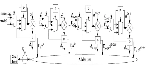
D. Key Equation Solver (KES) Block Architecture
In UHD decoder, KES block is employed to carry out steps B2.4, C4, C5, and D4. And presents the overall architecture of KES block and the internal structure of its two types of processing elements (PE). This KES Block heart of the Reed-Solomon Decoder. This KES block generates the Error locat or polynomial Ʌ(x). After the Error Locator polyn omial has been found, it is used to determine the Error Evaluator polynomial Ὡ(x). The KES block consists of 2t-1 PE0’s and 2t PE1’s.The detaile d operating scheme is presented as follows.
1) For mode-1 (step B2.4), in the r th iteration, ea ch register in PE0i/PE1i stores thecorresponding
coefficients of different polynomials . For each outer iteration, it takes 2β cycles to compute λi
(2β)
and δi
῀(2β)
as the coefficients of Ʌ(2β)(x) and Ʌ῀(2β)(x). Meanwhile, λi
῀(2β)
will also be computed and outputted into PT block to track the longest consecutive Ʌ῀(2β)(x) that are identical.
2) For mode-2, as a forementioned, KES block is arranged to carry out steps C4 and C5. Accordin gly, both of the initial values in registers and inp ut signals are different from those in mode-1, and they are operated based on the following schedule:
i. First, 2t-1 PE0’s compute step C4 (Ʌ*(x) = Ξ(αs+2t-2x) . ineach PE0i ,the second uppermost register
(denoted as group A) is initialized with ξi+1 in
addition,Ctrl1 and δ0 ῀(r)
are always set to 1 and 0, respectively.then after s+2t-2 cycles, thes e registers in group A just store the coefficients of polynomial Ʌ*
(x).
Position Track (PT) Block Architecture
PT block is used to track the longest consecutive polynomials that are identical (step B3) or positio ns of roots (steps C3.2 and C3.3) In mode-1 ,the inputted λi
῀(2β)
, λi (2β)
, δi
῀(2β)
from KES block at the lth outer iteration are denoted as λi
῀(l), λ
i(l), and δi
῀(l). In addition, λ i
῀(temp) represents λ i
῀(l-1),
whileλi ῀
(store) are the coefficients of current continuously identical Ʌ῀(2β)(x). Moreover λ
i
῀( (longest) stores the
coefficients of current longest continuously identical Ʌ῀(2β)
(x). Control signals shift and equal are generated from Schedule A. After l reaches n, λi( (longest) and δi
῀
(longest) are outputted as the coefficients of overall error locator polynomial Ʌ*
(x) and overall error eval uator polynomial Ὡ*
(x). For mode-2, Schedule B is proposed to calculate the single burst’s starting position s and its length f in sLBC algorithm. Notice that since finding roots of Г(x) has been implemented in Φ -block there is no need for PT block to carry out this function any more, but just receiving the signal outputted from Φ –block whi ch indicates whether Г(α i) or not. Then it is feas ible for PT block to implement Schedule B with a simple control unit. Hence the extra architecture of PT block for executing Schedule B is omitted in this section.
Chien Search and Error Correction
In this approach error locator polynomial and erro r value polynomial values are passed to the Chien search and Forney algorithm blocks. To find the error location, Chien search is the very good effic ient method. Chien search method is used for find ing error positions. the basic Chien search block. Error correction block is shown .Its basic idea is simple but efficient: If Ʌ(αi
) = 0 for current i , it indicates that the ith symbol of the received code- word is wrong and needs to be corrected. After obtaining the error positions, the following Forney algorithm is applied to determine the error value.
ϒi = Ὡ(Xi -1
) / Ʌ(Xi -1
)
Where Yi indicates error magnitude for the ith erroneous
symbol.
V. HARDWARE PERFORMANCE
28
capability, while UHD decoder can be still effective (mode-1 and mode-2). For random error-and-erasure corre ction (mode-3), the proposed UHD design has lo wer throughput than RiBM. However considering only half resource of KES block is utilized, if one additional copy of SC, CSEE, FIFO,and Ξ blocks are employed, its throughput can be approximatel y doubled by inputting two independent codewor ds into the decoder, which will outperform RiBM architecture significantly. Being the first RS deco der that is capable of correcting both of burst erro rs and random errors, the proposed UHD design provides an efficient and attractive unified solutio n for multi-mode RS decoding in practical applic ations. The proposed three work modes cover diff erent applications: mode-1 can be used for applic ations of low or moderate data rates (e.g., ADSL and DVB-T etc.); mode-2 is suitable for the medi um to high speed (e.g., 1–2 Gbps) systems, and mode-3 is a good choice for very high-speed opti cal communication.
Applications
Reed Solomon codes are error correcting codes that have found wide ranging applications throug hout the fields of digital communication and storage. Some of which include:
Storage Devices (hard disks, compact disks, DVD, barcodes)
Wireless Communication ( mobile phones , microwave links )
Digital Television networks.
Broadband Modems ( ADSL, xDSL, etc).
Deep Space and Satellite Communications Networks (CCSDS).
Future Work
The Future work is being directed toward integr ated circuit implementations ( like ASIC or FPGA implementations) of the proposed archi tectures and their incorporation into broadband communication systems such as those for very high-speed digital subscriber loops and wireless systems.
EXPERIMENTAL RESULTS
The Simulation results of proposed architecture are carried out using Xilinx ISE simulator.
Fig10: Simulation result of encoder
Fig12: Simulation result for decoder
Fig 15: Final output for proposed Architecture
VI. CONCLUSION
In this paper, a high-speed RiBC algorithm for RS codes for burst-error correcting, and a UHD architecture that can support three different dec oding modes are developed. The UHD decoder can achieve enhanced capability of correcting long burst of errors with good hardware efficien cy. The UHD architecture that can support three decoding modes is presented for the first time. Compare to traditional RS decoder the proposed architecture can achieve efficient burst error correcting capability.
REFERENCES
[1]. D. V. Sarwate and N. R. Shanbhag, ―High-sp eed architectures for ―Reed-Solomon decoders,‖ IEEE Trans. Very Large Scale Integr.(VLSI) syst. , vol. 9, no. 5, pp. 641–655, Oct. 2001.
[2]. T. Zhang and K. K. Parhi, ―On the high-speed VLSI implementation of errors-and-erasures corr correcting Reed-Solomon decoders,‖ in Proc. ACM Great Lake Symp. VLSI (GLVLSI), 2002,PP . 89– 93.
29
Integr. (VLSI) Syst., vol. 14, no. 9, pp. 937–950, Sep.2006.
[4]. E. Dawson and A. Khodkar, ―Burst error corr ecting algorithm for Reed-Solomon codes,‖ Elect ron. Lett., vol. 31, pp. 848–849, 1995.
[5]. L. Yin, J. Lu, K. B. Letaief, and Y. Wu, ―Burst-error-correcting algorithm for Reed Solom on codes,‖ Electron. Lett., vol. 37, no. 11, pp.695 –697, May 2001.
[6]. Y. Wu, ―Novel burst error correcting algorith ms for Reed-Solomon codes,‖ in Proc. IEEE Allerton Conf. Commun., Control, Comput.,2009, pp. 1047– 1052.
[7]. S. Shamshiri and K.-T. Cheng, ―Error locali- ty aware linear coding to correct multi-bit upsets in SRAMs,‖ in Proc. IEEE Int. Test Conf., 2009.
[8]. B.Sklar, ― Digital Communication Fundamen- tal and Application‖ Prentice Hall, Upper Saddle River, 2001.p.1104.
[9]. S.B.Wicker and V.K. Bhargava, eds ―Reed-Solomon codes and their applications‖ New york: IEEE press 1994.
[10]. Amina, P. Chio, I.A. Sahagun and D. J. Sab- ido IX ― VLSI Implementation of A (255,223) Reed- Solomon Error- Correction Codes ,‖ Roc. Of Second National ECE Conference.
[11]. Li Li, Bo Yuan ― Unified Architecture for Reed-Solomon decoder combined with burst error correction‖, IEEE transaction on VLSI systems,JULY 2012.
[12]. J.H. van Lint, ― Introduction to Coding Theory.Springer, New York 3rd Edition,1999.
[13]. W. Cary Hu_man; Vera Pless, ― Funda- mentals of Error-Correcting Codes‖ . Cambr- idge University Press; Cambridge, UK 1st Edition, 2010.
[14]. J.L. Massey, ― Shift-register synthesis and BCH decoding," IEEE Trans. Inform. Theory IT-15 (1969).