Volume 3, Issue 12 (September 2012), PP. 91-98
Development of Fuzzy Inference Scheme for LC Oscillator Design
S.R.Ghatage
1, T. D. Dongale
2, T .G. Kulkarni
2, R. R. Mudholkar
21
Department of Electronics, G.K.G College, Kolhapur 2
Department of Electronics, Shivaji University, Kolhapur
Abstract—Oscillators are an artefact of Electrical Technology. By and large oscillator designing can be viewed as a ‘Scientific Art’. Furthermore, the use of computer in the designing process of oscillator added the wings to it. Fuzzy-Logic-Computer-Aided-Design (FLCAD) using MATLAB FUZZY TOOLBOX amalgamates the ability of Fuzzy Logic to model colloquial propositions involved in the oscillator design. Designing even simplest of oscillator that is efficient and economical is a multi-fold process that runs through great deal of numerical manipulation. This is the intention to go for the development of tool-box type Fuzzy based CAD for oscillator designing. Fuzzy Logic is mainly exploited to make the trade-off decisions over numerical data and conflicting issues raised by conventional design techniques. For modelling of LC oscillator TSK method is used. The TSK method uses linear equations for consequences part. The ANFIS tool from fuzzy toolbox automatically generates such kind of linear equation by using numerical MATFILE data. The use of FIS has been extended to design of LC oscillators.
Keywords— Oscillator, Design Algorithm, Fuzzy Logic, Fuzzy Reasoning, TSK modelling
I.
INTRODUCTION
Fuzzy logic, proposed by L. Zadeh in 1965[1], emerged as a tool to deal with uncertain, imprecise, or qualitative decision-making problems. As the complexity of a system increases, it becomes more difficult and eventually impossible to make a precise statement about its system behaviour. Fuzzy logic is used in system control and analysis design, because it shortens the time for engineering development and sometimes, in the case of highly complex systems, is the economical way to solve the problem. Further it has ability to address huge data in the form Fuzzy Set. Basically, Fuzzy Logic (FL) is a multivalued logic, that allows intermediate values to be defined between conventional evaluations like true/false, yes/no, high/low, etc. Notions like ‘rather tall’ or ‘very fast’ can be formulated mathematically and processed by computers, in order to apply a more human-like way of thinking in the programming of computers. In this context, FL is a problem-solving methodology that lends itself to implementation in systems ranging from simple, small, embedded micro-controllers to large, networked, multi-channel PC or workstation-based data acquisition and control systems. It can be implemented in hardware, software, or a combination of both. FL provides a simple way to arrive at a definite conclusion based upon vague, ambiguous, imprecise, noisy, or missing input information. [1]
The conventional design of oscillator using manual technique involves good amount computation of design data on the resistor, inductor, capacitor and gain of amplifier by using design formulae. It is time consuming and tedious job. In some cases design assumptions made are based on crisp boundary that ends up in to failure of achieving the design objective. The MATLAB provide the great flexibility to design of Electronics circuit design. For oscillator design we used FUZZY TOOLBOX of MATLAB. The fuzzy approach can closely resemble the human thinking and hence some kind of decision making is possible under imprecise design data specifications. For oscillator design the FUZZY TOOLBOX prerequisites a large amount of numerical data in the form of MATFILE. This MATFILE data are used by Adaptive Neuro-Fuzzy Inference System (ANFIS) TOOL which is located in FUZZY TOOLBOX. It automatically creates required amount of input-output membership function and linear equations.
II.
DEVELOPMENT OF FUZZY BASED DESIGNING METHODOLOGY
Fig.1. Basic structure of fuzzy module
The fundamental phases involved in the designing of fuzzy system are as follows-
Phase-1: Identification of input/output variables, Determination of Operating Ranges [Universe of Discourse], Normalization of Universe of Discourse [Scaling Factor].
Phase-2: Expressing the variables by appropriate Fuzzy Sets [Fuzzy Quantization], Introduction of different membership functions [Shapes], Partition or Decomposition of Universe of Discourse, Selection of Linguistic Labels [Term Set] for each variable.
Phase-3: Formulation of knowledge pertaining to the problem in terms of fuzzy inference rules.
Rules elicitation from experienced human operator and/or designer.
Rule extraction from empirical data based on their trends.
Phase – 4: Choice of Inference Scheme/ Implication method
Mamdani Inference method.
Sugeno Inference method.[1]-[3]
Phase-5: Defuzzification of Solution Fuzzy Space, De-normalization of Universe of Discourse [Scaling Factors] [4]-[8]
Phase-6: Interpretation of Results
III.
MODELLING OF OSCILLATOR IN MATLAB USING FUZZY LOGIC FOR
HARTLEY OSCILLATOR
[9-12] Identification of Input-Output Performance Variables
Fuzzy Inference system (FIS) developed for Hartley Oscillator is of Multiple Input Single Output (MISO) type. Oscillator frequency and Inductance L1 has been identifies as an Input variable and Inductance L2 of phase shifting network
as Output variable. Keeping the capacitance value constant for each model the modelling of Inference Logic is implemented.
Reasoning-Process
For modeling of oscillator large amount of numerical data is required in the form of MATFILE. Hence here TSK (Sugeno) method is used for reasoning which consist of linear equation in the consequences part of form given by equation (1). [1]-[3]
y = mx + C (1)
A. Fuzzy Inference Scheme (FIS) for Hartley oscillator
gives faithful and required output from the model. When tuning is over, the model gives desirable output. The Rule Viewer and Surface Viewer display the transfer characteristics depicting the design policies.
B. Rule Base for Hartley Oscillator
The design objective are implemented in the form of inference rule which are enlisted as follows,
IF (input1 is in1mf1) AND (input2 is in2mf1) THEN (output is out1mf1) (1) IF (input1 is in1mf1) AND (input2 is in2mf2) THEN (output is out1mf2) (1) IF (input1 is in1mf1) AND (input2 is in2mf3) THEN (output is out1mf3) (1) IF (input1 is in1mf1) AND (input2 is in2mf4) THEN (output is out1mf4) (1) IF (input1 is in1mf1) AND (input2 is in2mf5) THEN (output is out1mf5) (1) IF (input1 is in1mf1) AND (input2 is in2mf6) THEN (output is out1mf6) (1) IF (input1 is in1mf1) AND (input2 is in2mf7) THEN (output is out1mf7) (1)
Remaining forty two rule only contain combination of two input and one output membership functions. The complete rule base can be put in form given by equation (2).
IF (frequency is in1mfn) AND (Inductance1 is in1mfn) THEN (Inductance2 is outmfn) (2)
Where n = 1 to 7.
C. FIS for Hartley Oscillator
The Fuzzy Inference Systems associated with input and output variables create a fuzzy mapping between the design variables. Here input variable is frequency, inductance L1 and output variable is inductance L2 at constant capacitance
value C = 0.1µf. Figure.2 depicts snap shot of FIS-Editor window for design structure of Hartley Oscillator.
Fig.2. FIS for Hartley oscillator
Fig.3. Input membership function (frequency)
For good results of modelling seven triangular membership functions have been considered. The knowledge base relevant to oscillator designing is formulated into fuzzy inference rules. The Figure.3.depicts snap shot of Membership function-Editor window for input variable ‘frequency’. The ranges of membership function for frequency are as follows-
μin1mf1(x) = L (x, 0, 2.22)
μin1mf2(x) = ˄ (x, 0, 2.22, 2.6)
μin1mf3(x) = ˄ (x, 2.23, 2.6, 3.0)
μin1mf4(x) = ˄ (x, 2.6, 3.0, 3.4)
μin1mf5(x) = ˄ (x, 3.0, 3.4, 3.78)
μin1mf6(x) = ˄ (x, 3.38, 3.78, 4.5)
The symbol ‘L’ stands for left bounded membership function, the ‘Γ’ for right bounded membership function and the‘˄’ symbol indicates the centred triangular membership function.
Fig.4. Input membership function (Inductance L1)
The Figure.4 depicts snap shot of Membership function-Editor window for input variable ‘Inductance L1’. The ranges of
membership function considered for Inductance L1 are as follows-
μin2mf1(x) = L (x, 0, 190)
μin2mf2(x) = ˄ (x, 0, 190, 275)
μin2mf3(x) = ˄ (x, 190, 275, 360)
μin2mf4(x) = ˄ (x, 275, 360, 450)
μin2mf5(x) = ˄ (x, 360, 450, 545)
μin2mf6(x) = ˄ (x, 450, 545, 650)
μin2mf7(x) = Γ (x, 545, 650, 650)
Fig.5. Output membership function (Inductance L2)
The Fuzzy-Logic-Computer-Aided-Design (FLCAD) employs Sugeno type individual rule based fuzzy logic inference. This is a process where contribution of each fuzzy logic rule is evaluated. The purpose of inference is to compute the overall decision outcome based on the individual contributions of each rule in the rule base. In the inference process each rule is individually fired by crisp-value of input variable (design specification/parameter) from Fuzzification module and clipped fuzzy sets representing the overall fuzzy output variable of design step under execution are obtained. Here output membership functions are linear equation and considered as, Out1mf1, Out1mf2, Out1mf3 up to Out1mf49.But for simplicity only seven output membership functions are shown in figure.5. This output membership function is fired according to rule base of system and input data to FIS.
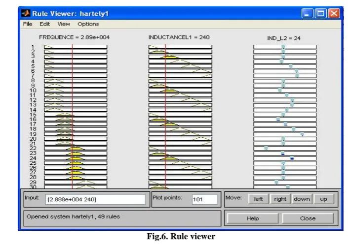
The output of the model can be viewed on rule viewer (figure.6). The rule viewer shows the defuzzified output of design model. For input variable frequency having the value of 28880.42 Hz, inductance L1= 240mH the model give the
Fig.6. Rule viewer
D. Numerical Data Base
The oscillator design model consists of many variables such as inductance, capacitance and frequency etc. For such type of modelling Sugeno type inference system takes data in the form of MATFILE depicted in table.1. The ANFIS use MATFILE data and train the model. [9]
Table 1: MATFILE sample design I (at C=0.1 µf) Frequency
(MHz)
Inductance L1 (mH)
Inductance L2 (mH)
Frequency Inductance L1 (mH)
Inductance L2 (mH)
41114.47 100 10 27429.97 270 27
39685.09 110 11 26178.18 300 30
38395.13 120 12 25083.48 330 33
37223.29 130 13 24115.55 360 36
35169.28 150 15 23251.66 390 39
34262.06 160 16 22232.16 430 43
32640.13 180 18 21335.99 470 47
31228.68 200 20 20540.13 510 51
29985.81 220 22 19660.22 560 56
28880.42 240 24 18740.09 620 62
IV.
MODELLING OF OSCILLATOR IN MATLAB USING FUZZY LOGIC FOR
COLPITT’S OSCILLATOR
Identification of Input-Output Performance Variables
FIS developed for Colpitt’s Oscillator is of MISO type. Oscillator frequency and Capacitance C1 has been
identifies as an Input variable and Capacitance C2 of phase shifting network as Output variable. Keeping the inductance
value constant for each model the modelling of Inference Logic is implemented.
Reasoning-Process
TSK (Sugeno) method similar to Hartley Oscillator design is used for reasoning with linear equation in the consequences part.
A. Fuzzy Inference Scheme (FIS) for Colpitt’s oscillator
Creation of FIS of Colpitt’s Oscillator is done in similar fashion as that of Hartley Oscillator Design Algorithm.
B. Rule Base for Colpitt’s Oscillator
The design objectives are implemented in the form of inference rule comprising 42 rules as given by equation (3).
C. FIS for Colpitt’s Oscillator
Here input variable is frequency, capacitance C1 and output variable is capacitance C2 at constant inductance value L = 1µH.
Figure.7 depicts snap shot of FIS-Editor window for design structure of Colpitt’s Oscillator.
Fig.7. FIS for Colpitt’s oscillator
Fig.8. Input membership function (frequency)
The ranges of membership function considered for frequency are as follows- μin1mf1(x) = L (x, 18, 54)
μin1mf2(x) = ˄ (x, 18, 54, 84)
μin1mf3(x) = ˄ (x, 54, 84, 120)
μin1mf4(x) = ˄ (x, 84, 120, 156)
μin1mf5(x) = ˄ (x, 120, 156, 190)
μin1mf6(x) = ˄ (x, 156, 190, 224)
μin1mf7(x) = Γ (x, 190, 224, 224)
The Figure.9 depicts snap shot of Membership function-Editor window for input variable ‘capacitance1’. The ranges of
membership function considered for capacitance are as follows-
μin1mf1(x) = L (x, 10, 36)
μin1mf2(x) = ˄ (x, 10, 36, 70)
μin1mf3(x) = ˄ (x, 36, 70, 114)
μin1mf4(x) = ˄ (x, 70, 114, 138)
μin1mf5(x) = ˄ (x, 114, 138, 172)
μin1mf6(x) = ˄ (x, 138, 172, 210)
Fig.9. Input membership function (capacitance C1)
Fig.10.Output membership function (capacitance C2)
The output of the model can be viewed on rule viewer (figure.11). The rule viewer shows the defuzzified output of design model. For input variable frequency of 19 KHz, capacitance C1= 134 µf the model gives the output value capacitance
C2 = 67.8 µf.
Fig.11. Rule viewers
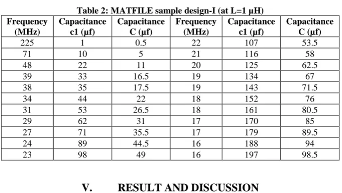
D. Numerical Data Base
Table 2: MATFILE sample design-I (at L=1 µH) Frequency (MHz) Capacitance c1 (µf) Capacitance C (µf) Frequency (MHz) Capacitance c1 (µf) Capacitance C (µf)
225 1 0.5 22 107 53.5
71 10 5 21 116 58
48 22 11 20 125 62.5
39 33 16.5 19 134 67
38 35 17.5 19 143 71.5
34 44 22 18 152 76
31 53 26.5 18 161 80.5
29 62 31 17 170 85
27 71 35.5 17 179 89.5
24 89 44.5 16 188 94
23 98 49 16 197 98.5
V.
RESULT AND DISCUSSION
The modelling package - Fuzzy-Logic-Computer-Aided-Design (FLCAD) amalgamates the ability of Fuzzy Logic to model colloquial propositions involved in the oscillator designing. This is the basis of our problem: ‘Development of Fuzzy Inference Scheme for Oscillator Design’. Basically, FLCAD can be of two types-
Embedded CAD Tools
Tool-Box type CAD Tools
FLCAD that we have developed specifically for oscillator designing belongs to ‘Tool-box type’ CAD Tool. Our FLCAD modeling tool falls under the category of Tool-Box type CAD Tools with physical design for almost all aspects addressable by Fuzzy Logic. This is further based on combination of constructive and iterative algorithm. The very idea of FLCAD is to exploit the trade-off decisions made over numerical data and conflicting issues raised by conventional design techniques. We exploited the Fuzzy Logic within the framework of ‘approximates reasoning’ in modeling the ‘trade-off’ solutions intermingled with numerical computations involved in the oscillator designing. The test trials have shown good resemblance with design results of non-fuzzy approach.
REFERENCES
[1]. Tanaka K. (Translated by Tiimira T.), An Introduction to Fuzzy Logic for Practical Applications. Springer-Verlag, New York, 1997, pp 1-119.
[2]. Sugeno. M. An introductory survey on fuzzy control, Information science, 1985, pp.59-83.
[3]. Takagi. T. and Sugeno. M., [1985], Fuzzy identification of system and its application to modeling and control. IEEE Transaction on system, Man and Cybernetics, pp.116-132.
[4]. Mamdani E.H. and Gaines B.R. (eds.), Fuzzy Reasoning and Its Applications, London, Academic Press, 1981
[5]. Zadeh L.A., Making Computers think like people, IEEE Spectrum, 1984
[6]. Zadeh L.A., commonsense knowledge representation based on fuzzy logic, IEEE Computer, 1983, pp.16-50.
[7]. Zadeh L.A., Fuzzy languages and their relation to human and machine intelligence, Proc. of the 1st Inter. Conf. on Man and Computer, Bordeaux, 1972
[8]. Driankov D., Hellendoom H. and Rein frank M., An Introduction to Fuzzy Control, Narosa Publishing House, New Delhi. 1996
[9]. www.mathworks.com, MATLAB®, MATLAB® Compiler, and other MATLAB family Products.
[10]. Tukaram. D. Dongale, T .G. Kulkarni, P. A. Kadam, R. R. Mudholkar, Fuzzy Model of Thermistor, International Journal Of Applied Engineering Research, Dindigul, ISSN - 0976-4259Volume 2, No 1, 2011