IJEDR1801113
International Journal of Engineering Development and Research (www.ijedr.org)
661
Flexural Behavior of Composite Beams Under Three
Point Loading
1
P.Deepthi ,
2S.Suresh Babu,
3V.S.Satheesh
1P.G.Student,2Head Of The Department ,3Assistant Professor 1Department of Civil Engineering,
1Adhiyamaan College Of Engineering, Hosur, Tamilnadu, India
________________________________________________________________________________________________________
Abstract—In recent days, composite beams have recently undergone increased usage throughout the world, which have been influenced by the improvement of high strength concrete enabling these beams to be considerably economized. Beams are designed to resist the majority of loads. This project presents an experimental study on the flexural behavior of composite beams made of steel channel section with and without lip encased with concrete of size 1300mm x 150mm x 150mm under three point loading. The conventional concrete beams and composite beams were casted, cured for 28days and then subjected to three point loading. In this project, it is exposed to determine the load-deflection behavior, ultimate load and failure pattern of the beam specimens by the experimental program.
IndexTerms—Cold formed steel section, flexural behavior, crack pattern.
________________________________________________________________________________________________________
I. INTRODUCTION
Composite construction is well established for some decades as a construction method but it has traditionally used hot rolled steel sections rather than light steel (cold formed) sections. The main components of traditional composite construction have been hot rolled steel framework, steel decking, shear connectors and in-situ concrete with mesh reinforcing steel. The benefits of this construction method are several and the most important of them are speed of construction due to the rapid erection of the steel framework, economy in use of materials, robustness to damage and good performance in service. To these benefits some more can be added if light steel sections are used instead of the traditional hot rolled. The advantage that light steel gives are basically two: that cold formed steel is cheaper that hot rolled and that is also lighter in weight.
Light steel framing comprises galvanized cold formed steel sections of C or Z or similar forms of 1.2 to 3.2 mm thickness. Previous works have studied how these sections behave as beams or columns under different loads cases, but the composite action of light steel sections with in-situ concrete is a field not yet fully explored. The flexural capacity of the beam is influenced only by compression stresses of the concrete and the tensile stress of the steel reinforcement.
Composite construction achieves important benefits by making steel and concrete work together, but these advantages can be improved if light cold formed steel sections instead of hot rolled sections are used. The advantages of the light steel composite construction are:
• To get a rapid erection of the steel framework. • Good performance in service.
• Weight and cost of materials are reduced.
The main objective is therefore to explore innovative composite construction technology where light steel sections act compositely with in-situ concrete. This will lead to increase speed of construction, longer spans, economy of materials and good performance in service.
Light steel sections
The thickness of the sheet steel used in cold formed sections, light steel sections, is typically 0.9 to 3.2 mm. The method used to protect the steel of the corrosion is with hot dip galvanizing of preformed strip steel. It protects the steel by loss of the zinc surface. Light steel sections are shaped to suit particular applications. The basic shapes, especially in building applications, are the C and Z sections, but there is a wide range of variants of these basic shapes, like those with edge lips, internal stiffeners and bends in the webs. Also are common the sections form as modified I section and the top-hat section. The sections are also joined together back to back or toe to toe to form compound sections as double C sections.
Advantages of cold formed steel section
• Light weight • High strength
IJEDR1801113
International Journal of Engineering Development and Research (www.ijedr.org)
662
Study of literatures
• It was found that, an increase in the thickness to width ratio lead to increase in the ultimate load by about 43% • The corrugation in web increases the stiffness and ductility for composite beam.
• The use of HSC in the compression zone significantly increased the shear strength of the composite beams. • Due to its larger stiffness, there is less deflection in the composite beams than the steel beams.
• The span to depth ratio and shear span to depth ratio have an influence on the increase in the load carrying capacity of the composite beams.
• Composite section has greater horizontal shear strength and ultimate strength when compared to conventional concrete.
II. METHEDOLOGY
The mix design is done for M35 concrete as per IS: 456-2000 and IS 10262-2009. The water cement ratio of 0.4 was used to prepare the concrete mix. Totally 5 number of specimens in which 3 of them were casted and cured for 28 days, where the other two specimen is steel section with and without lips. After the curing period the specimens were subjected to testing using loading frame under three point loading to determine the flexural strength, crack patterns.
III. EXPERIMENTAL PROGRAM
Materials
1. cement
53 Grade Portland pozzolona Cement (PPC) conforming to IS: 8112-1989, having a specific gravity of 3.15Initial setting time 35 minutes, Final setting time - 585 minutes , was made use of, in the casting of the specimens.
2. fine aggregate
The fine aggregate (river sand) used was clean dry sand. The sand was sieved in 4.75mm sieve to remove all pebbles as per IS 383-1978. The specific gravity of the fine aggregate is 2.67 (zone 3).The fineness modulus of aggregate was 2.62.
3. coarse aggregate
Crushed stones of size less than 20mm were used as coarse aggregateas per IS 383-1970.The specific gravity 2.67,water absorption 1.50, fineness modulus 6.04.
4. Steel section
Cold formed steel sheet of thickness 3mm was used for the fabrication. The cold formed steel sheets were fabricated by bending sides in to suitable dimensions along with lips of 25mm and without lips.
Testing
After the curing period of 28 days, beam specimens were kept for 24 hours in a dry state and then they were cleaned to remove grit and dirt. Then the beam specimens were whitewashed to facilitate easy detection of cracks. The beam specimens were tested in a loading frame of 1000 kN capacity and proving ring subjected to three point loading.The deflection of the beam specimens was noted down for every increment in the load till the failure. The first crack load, deflection at first crack load, ultimate load and deflection at ultimate load were noted down and the crack pattern was marked on the beam.
IV. RESULTANDDISCUSSION
Load Vs Deflection Characteristics
Load-deflection behavior is the principle constituent of the flexural behavior of the beams. As the load increases the deflection of the beam begins. Load will be directly proportional to deflection. Load-deflection curve serves as the basis for calculating many structural parameters like, deflection, ductility etc.
Figure 1: Load Vs Deflection Curve for Conventional Beam 0
2 4 6 8 10 12
0 10 20 30 40 50
Def
lect
io
n
in
m
m
Load in kN
LEFT DEFLECTION
MIDDLE DEFLECTION
IJEDR1801113
International Journal of Engineering Development and Research (www.ijedr.org)
663
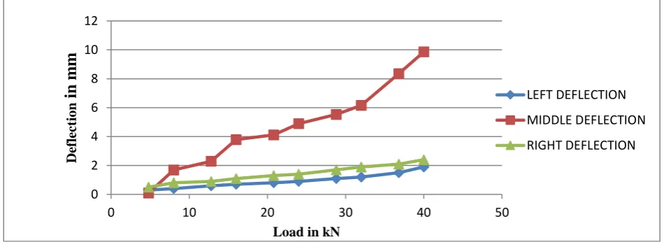
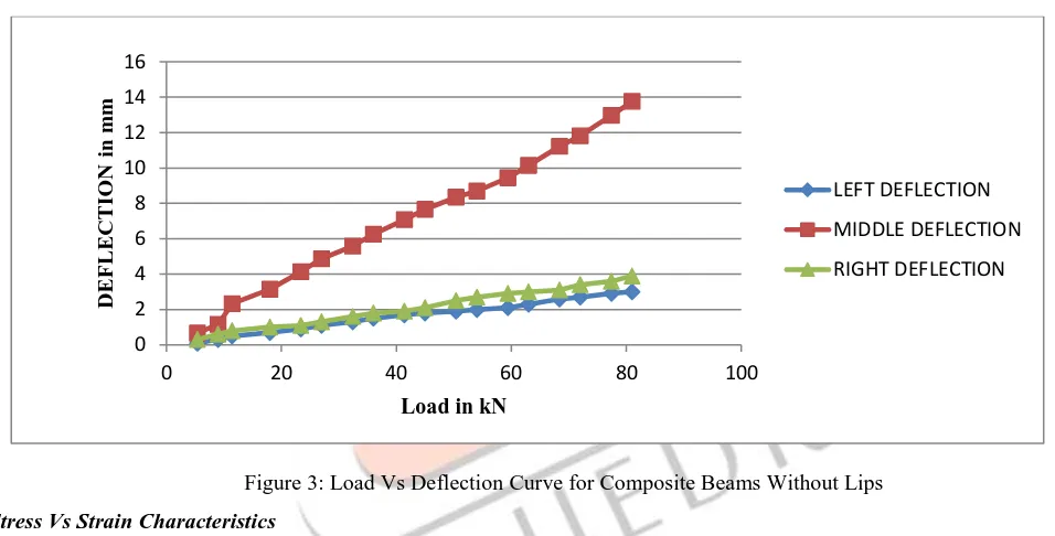
Figure 2: Load Vs Deflection Curve for Composite Beams With LipsFigure 3: Load Vs Deflection Curve for Composite Beams Without Lips
Stress Vs Strain Characteristics
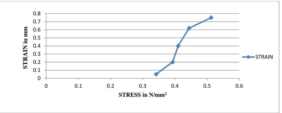
Stress strain curve is a behavior of material when it is subjected to load.in this diagram stresses are plotted along horizontal axis and a result of these stresses, corresponding strains are plotted along the vertical axis.
Figure 4: Stress Vs Strain Curve for Conventional Beams 0
2 4 6 8 10 12 14
0 50 100 150
DE
F
L
E
CT
IO
N
in
m
m
Load in kN
LEFT DEFLECTION
MIDDLE DEFLECTION
RIGHT DEFLECTION
0 2 4 6 8 10 12 14 16
0 20 40 60 80 100
DE
F
L
E
CT
IO
N
in m
m
Load in kN
LEFT DEFLECTION
MIDDLE DEFLECTION
RIGHT DEFLECTION
0 0.5 1 1.5 2 2.5 3
0 0.05 0.1 0.15 0.2 0.25
ST
R
A
IN
I
n m
m
STRESS in N/mm2
IJEDR1801113
International Journal of Engineering Development and Research (www.ijedr.org)
664
Figure 5: Stress Vs Strain Curve for Composite Beams With LipsFigure 6: Stress Vs Strain Curve for Composite Beams Without Lips
V. CONCLUSION
• Due to its larger stiffness, there is less deflection in the composite beams than the steel beams.
• It is observed that, cracking load for composite beams is thrice more than the cracking load for composite beams.
• The ultimate load of composite beams with lips is 100.2KN is greater than the composite beams without lips is 81 KN and conventional beam is 40KN.
• Due to its larger stiffness, there is less deflection in the composite beams than the steel beams.
• It can be concluded from the study that, the strength of the channel section can be exploited in a much better way by using the channel section, since the failure of the beam was accompanied by failure of the concrete in compression.
REFERENCES
[1] T.Sowmya and T.Valsa Ipe “Experimental and Analytical Studies on Hat and U-Shaped Cold-Formed Steel Sections Subjected to Bending” Proceedings of the Sixth Structural Engineering Convention, SEC- 2008 December 18-20,2008, Chennai,pp.1301-1311.
[2] Mirgange Manjunath and Valsa Ipe “Experimental studies on the effect of shear connectors on flexural strength of cold formed steel concrete composite beam” (2009).
[3] A.T.Samuel “Theory and Practice of Composite Construction with Case Studies” Proceedings of The Workshop on Advances in Structural Steel-Concrete Composite Construction ASC-2001 February 26- 28,2001.Bangalore.pp.69-90. [4] Laith Khalid Al-Hadithy Omer Khalid Al- Kerbooli(2008) “experimental and finite element investigation of composite
beams consisting of reinforced concrete prisms cast into steel channels” the 1st regional conference of eng. sci. NUCEJ spatial issue vol.11,no.1, 2008 pp 1-18.
0 0.1 0.2 0.3 0.4 0.5 0.6 0.7 0.8
0 0.1 0.2 0.3 0.4 0.5 0.6
ST
R
A
IN
in
m
m
STRESS in N/mm2
STRAIN
0 0.5 1 1.5 2 2.5
0 0.1 0.2 0.3 0.4 0.5
ST
R
A
IN
in m
m
STRESS in N/mm2
IJEDR1801113
International Journal of Engineering Development and Research (www.ijedr.org)
665
[5] P.S.Patil, M.G.Shaikh (2013)“A study of effect of shear connector in composite beam in combined bending and shear byANSYS” international journal of innovative technology and exploring engineering (IJITEE) ISSN: 2278-3075, volume-3, issue-3, august 2013..
[6] Atif M. Abdel Hafeza, M.M. Ahmeda, A.S. Alamaryb, A.M.Mohmoud “Behavior of simply supported composite concrete-steel beam with corrugated web under vertical loads” journal of engineering sciences, Assiut university, vol. 40, no 1, pp.93-108, January 2012.
[7] Qing Quan Liang,Brianuy,Mark.A.Bradford and Hamid R Ronagh”Strenght analysis of steel-concrete composite beams in combined bending and shear "Journal of structural engineering ASCE/October 2005/1593.
[8] Guo-qiang Li,xianhui Li and Liang Li “Experimental study on the bend and shear behaviors of steel- concrete composite beams with notched web of inverted T-shaped steel section” international journal of steel structures september 2012, vol 12, no 3, 391- 401.
[9] Alex Remennikov, Marcus Roche " New composite construction of hybrid beams combining steel inverted t-section and RC flange".
[10] Shweta A. Wagh, Dr. U. P. Waghe “Comparative study of R.C.C and steel concrete composite structures” intl. journal of engineering research and applications. ISSN : 2248-9622, vol. 4, issue 4( version 1), April 2014, pp.369-376.
[11] Weiweilin and Teruhikoyoda “Experimental and numerical study on mechanical behavior of composite girders under hogging moment” advanced steel construction vol. 9, no. 4, pp. 309-333 (2013).
[12] Johnson, R. P.: composite structures of steel and concrete – beams, slabs, columns, and frames for buildings. 2nd edition, oxford (UK): Blackwell science ltd., 1994. vol.1.
[13] Dr. D. R. Panchal "Advanced design of composite steel-concrete structural element" international journal of engineering research and applications www.ijera.com ISSN : 2248-9622, vol. 4, issue 7( version 2), July 2014, pp.124-138. Vinay,N,
Harish, M.L and Prabhakara ,R (2015) “Experimental investigation on the flexural behaviour of the steel
concrete composite beams” International Research journal of engineering and technology, 2(7), 1293-1301.
[14]Moynihan, M.C. and Allwood, J.M. (2014). “Viabilty and performance of demountable composite
connectors.” J Constr Steel Res, 99, 47-56.
[15]
David, L. and Jeffrey, A.,L. (2013) “Testing and analysis of composite steel-concrete beam flexural strength.”
International journal of structural and Civil Engineering Research, 90-103.
[16] Aldeen, S., Ranzi, G. and Vrcelj, Z. (2011) “Long –Term experiments of composite steel concrete beams, The twelth east Asia pacific conference on structural Engineering and Construction, 14, 2807 -2814.
[17]Dhinesh N P, Satheesh V S, “Flexural Behaviour of Hollow Square Beam”, International Journal of Scientific Engineering and Applied Science, Vol 3, Issue 3, March 2017, PP 236-242, ISSN 2395 3470
[18]Satheesh V S, Sivanadiyan S, Soniya H, Sridar M, Syed Vaseem Akram R, “Flexural Behaviour of Fiber Reinforced Hollow Square Beam”, International Journal of Engineering Research - Online, Vol 5, Issue 2, March - April 2017, PP139-146 , ISSN: 2321-7758