MODERN DESIGN OF 16 POINT FFT ALGORITHM
USING GRAPH TECHNIQUE FOR OFDM
RELEVANCE’S
Avuluri Anjaneyulu
1, S.V.V.N. Chanukya
2, L.Srinivas Reddy
31
M. Tech Scholar (DECS),
Nalanda Institute of Engg & Tech.
(NIET),
Siddharth Nagar, Guntur, A.P, (India)
2
Asst. Professor (ECE), Nalanda
Institute of Engg & Tech.
(NIET),
Siddharth Nagar, Guntur, A.P, (India)
3
Assistant. Professor (ECE),
Nalanda Institute of Engg & Tech.
(NIET),
Siddharth Nagar, Guntur, A.P. (India)
ABSTRACT
DFT and FFT are widely using transforms in the applications of DSP. These are useful where filtering and
correlation is needed. In this article, we are going to present 16 point FFT (Fast Fourier Transform) and the
time to complete the total computation. Main goal of this paper is to implement 16 point FFT with Radix 4 with
less computational time. In DSP, FFT is a fundamental building block. Here the FFT algorithm is of
Decimation in Frequency (DIF). This algorithm is widely applied in digital communication systems. This is
designed by using Verilog HDL and synthesized on XILINX tool.
Keywords— Decimation In Time And Frequency, Discrete Fourier Transform And Fast Fourier
Transform
I.
INTRODUCTION
The method of changing from time representation to frequency representation is called the Fourier
Transformation. In Fourier analysis, present most and preferred transform is discrete fourier transform (DFT).
The DFT equation for a sequence is defined as follows:
Where WN is twiddle factor. Discrete Fourier Transform is a method used in signal processing. One special and
efficient method used to compute the DFT process. FFT is a faster version DFT. This FFT method includes
butterfly operation. In these butterfly operations of FFT, twiddle factors have referred as the root-of-unity
complex multiplicative constants. These twiddle factors have used to combine smaller discrete fourier
transforms as recursively. Practically, there is only real values will present at the input because of the time
domain but we are assuming imaginary values including real values at the input sequence for our convenience.
The direct computation of X(k) for each value of k performs N complex multiplications (4 times of N - real
N values, the operation of DFT need to require complex multiplications of N2 and complex additions are an
amount of N2 – N.
A standard three loop structure can able to use in the computation of FFT. Radix will differentiate the FFT
process. Mainly there are two different radix are present in the process i.e., radix-2 and radix-4. Here 2 and 4
indicates the size of the butterfly. Representation of the number of data points in DFT makes a difference in
both radix-2 and radix-4. In radix-2, the representation is in the power of 2 i.e., N = 2v and in radix-4, the
representation is in the power of 4 i.e., N = 4v. Radix-4 can able to perform the operation four times faster than
the radix-2. For radix-4, 4 banks of memory needed to store the data. Number of stages for radix-2 is log2N and
for radix-4, it is log4N. Number of multiplications per stage is N/2 thus total multiplications N/2 log2N in
radix-2 and coming to radix-4 it is 3N/4 and total of 3N/8 log2N. Coming to number of additions per stage is N and
total of N log2N in radi-2 and for radix-4 it is 3N and total of 3N/2 log2N.
We need to minimize the memory storage. For that, butterfly results must be stored in the same locations they
were obtained. From this, the N- point FFT requires N-complex valued locations.
II.
ALGORITHM
AND
ANALYSIS
OF
FFT
FFT processor is a first designed chip. In OFDM transmitter and receiver it is positioned at the centre. Butterfly
operations will have to do for the result. These butterfly operations are the building blocks of FFT. In FFT
algorithm, several techniques have developed. Here we are going to consider two techniques i.e., DIT and DIF.
The difference between two butterfly operations of these two techniques has shown in below.
Fig 1: (A) Radix 2 DIF Butterfly (B) Radix 2 DIT Butterfly
As shown in above figure, the difference in between these two types is position of twiddle factor multiplication.
It is performed either after or before the addition and subtraction.
The hardware architecture of FFT has divided into two classes i.e., memory based architecture and pipeline
based architecture.
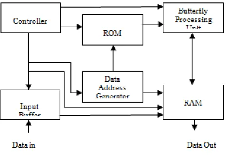
2.1 Memory Based Architecture
This architecture is shown in below fig 2. The memory based architecture increases utilization rate of the
elements of butterfly processing and reduces the multiple butterfly’s redundancy. This architecture has one or
two large memory blocks and all the data is accessed from the block of centralized memory where as in
pipelined, it uses small separated memory blocks, those cooperate with the local arithmetic units. Depending on
the butterfly processing element and the buffering strategies utilized during the process of FFT, memory based
architecture has divided into several independent types. This architecture have several subunits, these are:
a) Controller
b) A set of buffer
c) ROM
d) Butterfly processing unit
2.2 Pipeline Based Architecture
This pipelined architecture is non-stopping process. It has smaller latency with low power consumption. It is
characterized by real-time. For processor which has using pipeline architecture need to replace a series of
smaller memories with a N-word memory block. In this type of architecture input data is read in series only.
This architecture has classified into two types.
These are:
I. Single path architectures
II. Multi path architectures.
There are two kinds of buffering strategies were present in this architecture.
These are:
I. Delay-Commutator Architecture
II. Delay-Feedback Architecture
The FFT processor has a modular design and it consists of the following modules:
1. Butterfly processor
2. Address generation unit and
3. Micro coded state machine
2.3 Butterfly Processor
To carry out the complex butterfly operations, this processor is present.
Fig 3: Butterfly Operation
We used CSDs (canonical signed digit multiplication) instead of complete digital multiplier to do the
multiplication process with the twiddle factors. In CSDs, the multiplication has done with shifts and additions.
2.4 Address Generation Unit (AGU)
The address bus, which is going to the memory has controlled by this address generation unit. The FFT
processor works concurrently on the 8 dual port memory banks for read and write. The address mapping scheme
has used here to ensure that read and write operations hasn’t worked on same memory location at the same time.
It controls 8 read address buses and 8 write address buses.
2.5 Micro Coded State Machine
As the FFT processor’s process is going on there is need to store or to generate control signals at every level of
processing. For that this machine has needed. It stores or generates all the control signals, and its progression is
controlled by the clock. It is necessary to reset the state machine counter and signals before starting a new 16
point FFT operation, a reset signal is used to reset i.e., “en_fft”. Another signal “done_fft” is asserted by the
processor after the completion of the FFT calculation. We need to swap the real and imaginary parts if the
inverse FFT process is to do.
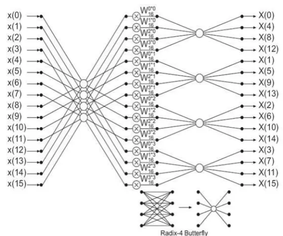
The proposed 16 point radix 4 DIF FFT butterfly diagram has shown in below fig 4. For hardware realization of
FFT, multi-bank memory and "in place" addressing strategy are often used for the realization of FFT hardware.
These are holds a key operation to speed-up the memory access time and minimize the hardware consumption
i.e., requires less area and low power consumption. Already have to know that r banks of memory are needed to
store data for radix-r FFT. There is the each memory bank could be two-port memory. The outputs are replaced
in the same memory location where the inputs have stored. This is the process called as “in-place” strategy. An efficient addressing scheme is needed to realize the FFT process in parallel and pipelined. This scheme is used
to avoid the conflict of data.
IV. SIMULATION RESULTS
Here we have designed the FFT using the Verilog HDL. The same design is synthesised in Xilinx ISE 13.2.
V. CONCLUSION
This paper presented the efficient FFT architecture of 16 point radix 4 FFT. It is with the technique of
Decimation in time. The design is developed by using Verilog HDL and synthesized on XILINX tool. This
paper has concluded that the reduction of operations and complexity of the system over existing systems. The
reduction of operations makes the reduction in area on chip. By this, we have proved that the technique
consumes less power and area. Future research has to base on the 64, 4K, 16K and more number of points and
REFERENCES
[1] Saad Bouguezel, M. Omair Ahmad,“IMPROVED RADIX-4 AND RADIX-8 FFT ALGORITHMS”IEEE.
Department of Electrical and Computer Engineering from Concordia University 1455 de Maisonneuve
Blvd. West Montreal, P.Q., Canada.
[2] Ali Saidi, “DECIMATION-IN-TIME-FREQUENCY FFT ALGORITHM” Motorola Applied Research,
Paging and Wireless Data Group Boynton Beach.
[3] J.G.Proakis and D.G.Manolakis, “Digital Signal processing, Principles, algorithms and applications”
Prentice Hall India Publication.
[4] L. Xiaojin, L. Zongsheng Lai, and C. Jianmin Cui, “A low power and small area FFT processor for OFDM demodulator”, IEEE Transactions on Consumer Electronics, 53(2):274-277, May 2007.
[5] M. C. Pease, “Organization of large scale Fourier processors”, J. Assoc. Comput. Mach., 16:474–482, July
1969.
[6] E. H. Wold and A. M. Despain, “Pipeline and parallel-pipeline fft processors for vlsi implementations,”
IEEE Trans. Comput., vol. 33, no. 5, pp. 414– 426, May 1984.
[7] M. Hasan and T. Arslan “Implementation of low power FFT processor cores using a novel order-base
processing scheme,” in Proc. IEEE Circuits Devices Syst., June 2003, vol. 150, pp. 149–154.
[8] D. Cohen, “Simplified control of FFT hardware”, IEEE Trans. Acoust., Speech, Signal Processing,
24:577-579, December 1976.
[9] Alan V. Oppenheim, Ronald W. Schafer, “Digital Signal Processing”, 3rd edition, Pearson
Education,2009.
[10] C.Gonzalez, V.Rodellar, A.Alvarez, E.Martinez and P.Gomez, “A Portable Hardware Design of a FFT Algorithm”, in Proc. Latin American Applied Research, 37:79-82(2007), pp 79-82.
[11] S. He and M. Torkelson, “A new approach to pipeline FFT processor”,10th International Parallel
Processing Symposium (IPPS 96), April 1996, pp 766-770.
[12] Xilinx Co. “Xcell journel vol 58-59”, 2007 spring.
[13] Xilinx, Inc., http://www.xilinx.com/
AUTHOR DETAILS
AVULURI ANJANEYULU, pursuing M. Tech (DECS) from Nalanda institute of Engineering and Technology (NIET), Siddharth Nagar, Kantepudi village, Satenepalli mandal, Guntur Dist., A.P, INDIA. His interest in digital concepts and has speciality to develop algorithms.
S.V.V.N. Chanukya, has received his M.tech degree and currently working as an Assistant professor (DIP) from Nalanda institute of Engineering and Technology (NIET), Siddharth Nagar, Kantepudi village, Satenepalli mandal, Guntur Dist., A.P, INDIA. He has specialized in image processing and has ability to design filter techniques.
L.SRINIVAS REDDY, He completed his post graduation in DECS. His area of interest includes digital electronics, digital communication, digital system design and VLSI technology and design. His research areas are optimal communication technology. He is currently working as Asst.professor (ECE) from Nalanda institute of Engineering and
Technology (NIET), Siddharth Nagar, Kantepudi village, Satenepalli Mandal. Guntur Dist.,