Optimization of FRM FIR Digital Filters Over
CSD and CDBNS Multiplier Coefficient Spaces
Employing a Novel Genetic Algorithm
Patrick Mercier, Sai Mohan Kilambi, and Behrouz Nowrouzian
Department of Electrical and Computer Engineering, University of Alberta, Edmonton, Alberta T6G-2V4, Canada Email:{pmercier, skilambi, nowr}@ece.ualberta.ca
Abstract— It is well known that frequency response masking
(FRM) FIR digital filters can be designed to exhibit very sharp-transition bands at the cost of slightly larger filter lengths as compared to the conventional FIR digital filters. The FRM FIR digital filters permit efficient hardware implementations due to an inherently large number of zero-valued multiplier coefficients in their transfer functions. The hardware complexity of these FIR digital filters can be fur-ther reduced by employing computationally efficient number systems for the representation of the constituent non-zero-valued multiplier coefficients. This paper presents a novel genetic algorithm for the design and discrete optimization of FRM FIR digital filters over the conventional canonical signed-digit (CSD) as well as the emerging double base number system (DBNS) multiplier coefficient spaces. This genetic algorithm is based on a pair of indexed look-up tables (LUTs) of permissible CSD/DBNS numbers whose indices form a closed set under the genetic algorithm operations of crossover and mutation. The CSD/DBNS values themselves permit pre-specified wordlengths and pre-specified number of non-zero bits. The salient feature of the proposed ge-netic algorithm is that it automatically leads to legitimate CSD/DBNS multiplier coefficients without any recourse to gene repair during optimization. The main features of the proposed genetic algorithm are demonstrated through its application to the design of a pair of lowpass and bandpass FRM FIR digital filters.
Index Terms— Frequency Response Masking Approach,
Dig-ital Filters, Genetic Algorithms, Optimization, Canonical Signed Digit, Double Base Number System.
I. INTRODUCTION
A vast body of literature exists for the design of computationally efficient FIR digital filters [1]–[3] and their corresponding hardware implementations [4], [5]. In many practical applications, such as audio signal processing, FIR digital filters with sharp transition bands are required [6], [7]. Since the length of a FIR digital filter is inversely proportional to its transition bandwidth [2], [8], FIR digital filters with sharp transition bands lead to high computational complexity. Consequently, the resulting FIR digital filters occupy large chip areas and consume high amounts of power in their VLSI hardware implementations. In general, the multiplication operation
This paper is based on “Design of FRM Digital Filters Over the CSD Multiplier Coefficient Space Employing Genetic Algorithms,” by Patrick M. Mercier and Behrouz Nowrouzian, Proceedings of the 2006 IEEE International Conference on Acoustics, Speech and Signal Processing, Toulouse, France, May 2006.
is the most cost-intensive part in the VLSI hardware implementation. Therefore, there is every incentive to reduce the number of multiplication operations in the FIR digital filter realization.
The frequency response masking (FRM) FIR digital filter design technique employs lower order digital sub-filters with gradual transition bands in such a manner as to realize very sharp transition bands in the overall FIR digital filter. The resulting FRM FIR digital filters turn out to have an inherently large number of zero-valued mul-tiplier coefficients, leading to a substantial reduction in the computational complexity of the resulting FIR digital filter [3]. The constituent digital subfilters are designed by using popular FIR digital filter design techniques such as the Parks-McClellan approach [1]. A further reduction in the corresponding hardware complexity of the FRM dig-ital filters can be achieved by constraining the multiplier coefficients values to conform to computationally-efficient number systems such as the signed power-of-two (SPT) system [9]. This number system permits the representation of the multiplier coefficients having only a few non-zero bits within the coefficient wordlength, permitting the decomposition of the multiplication operation into a finite series of shift and add operations.
FIR digital filters incorporating SPT multiplier coeffi-cient representation are commonly referred to as “multi-plierless” digital filters [9]. However, since the SPT rep-resentation of a given number is non-unique, it gives rise to redundancy in the multiplier coefficient representation. This redundancy can adversely affect the corresponding computational complexity due to repetitive recourse to compare operations.
The canonical signed-digit (CSD) and canonical DBNS (CDBNS) form a pair of practical special cases of the SPT number system which circumvent the above redundancy problem by limiting the number of non-zero bits in the number representation. If used in combination with subexpression sharing and elimination, the CSD/CDBNS multiplier coefficient representations can lead to substan-tial reduction in the cost of the VLSI hardware imple-mentation of the FIR digital filters [5], [10].
shift and add operations [11]. The DBNS number systems, on the other hand, employ two orthogonal bases for a sparse two-dimensional multiplier coefficient representa-tion [12].
One can distinguish between two different techniques for the optimization of FIR digital filters, namely, gradient-based and discrete optimization approaches. Dur-ing the past few decades, a number of practical techniques have been developed for the gradient-based optimization of FIR digital filters. In [13], an integer programming technique was developed for the corresponding opti-mization over the SPT multiplier coefficient space. This approach is not suitable for the optimization of FRM FIR digital filters, mainly due to the fact that it optimizes the constituent digital subfilters separately, giving rise to sub-optimality. An optimization technique based on Remez Exchange algorithm may provide a speed advantage over the linear programming approach. However, it too suffers from a similar sub-optimality problem [14]. In [15], an alternative approach based on the unconstrained weighted least-squares criterion was developed for the simultaneous optimizations of the digital subfilters constituent in the FRM digital filter proper. Non-convex optimization ap-proaches such as semi-definite programming and second-order cone programming have also been applied to the optimization of FRM digital filters [16], [17]. However, these techniques involve a large number of constraints that adversely effect the computational efficiency of the optimization.
Genetic algorithms (GAs) have emerged as promising candidates for the design and discrete optimization of FIR digital filters, particularly due to the fact that they are capable of automatically finding near-optimum solutions while keeping the computational complexity of the algo-rithm at moderate levels. They allow a robust search of the solution space through a parallel search in all directions without recourse to gradient information [18].
In this paper, a novel GA is developed for the design and optimization of FRM FIR digital filters over the CSD [19] and the CDBNS [20] multiplier coefficient spaces.
This paper is organized as follows: Section II presents an overview of FRM FIR digital filter design approach. Section III is concerned with a brief discussion of the CSD and CDBNS number systems. section IV gives a general overview of GAs. Section V presents a GA for the optimization of finite-precision FRM FIR digital fil-ters. Section VI illustrates the proposed GA optimization through its application to the design of a lowpass and a bandpass FRM FIR digital filter over the CSD and CDBNS multiplier coefficient spaces. Finally, Section VII summarizes the main conclusions of the paper.
II. OVERVIEW OFFRM FIR DIGITALFILTERDESIGN APPROACH
Let H(z) represent the transfer function of a de-sired FRM FIR lowpass digital filter. Furthermore, let
Hejωrepresent the frequency response associated with
H(z), wherez (ω, respectively) represents the discrete-time complex (real, respectively) frequency-variable. In addition, letωp andωs represent, respectively, the pass-band edge and the stop-pass-band edge frequencies associated with the magnitude frequency-response Hejω, with ∆ = (ωs−ωp)representing the corresponding transition bandwidth1. Finally, let
Ha(z)represent the transfer func-tion of a linear phase low-pass FIR bandedge-shaping digital subfilter with a passband edge frequency of θ, and a stopband edge frequency of φ, and let Haejω represent its corresponding frequency response as shown in Fig. 1. In this way, if Hb(z) represents a transfer function complimentary toHa(z), then [3], [21]
Hb(z) =z−(N−1)/2−Ha(z). (1)
The magnitude frequency response of the complementary digital filterHb(z)is shown in Fig. 2.
The desired FRM FIR digital filter transfer function
H(z) can be realized in terms of Ha(z) and Hb(z) in accordance with
H(z) =HazMHma(z) +HbzMHmb(z), (2) whereHazM and HbzM are obtained from Ha(z)
andHb(z) by interpolation, i.e. by replacing each unit-delay byM-unit delays as illustrated in Fig. 3, and where
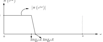
Hma(z)andHmb(z)represent masking digital subfilters (c.f. Figs. 4 and 6) suppressing the unwanted image bands inHazMandHbzM. The transition bandwidth of the resulting FIR digital filter is also scaled by the interpolation factor M, resulting in a narrow-transition bandwidth of∆/M. The overall lowpass FRM FIR digital filter structure can be realized as shown in Fig 8.
ω
Ha“ejω”
θ φ
R(ω)
π
0 1
Figure 1. Magnitude Frequency Response of the Bandedge-Shaping Digital SubfilterHa(z)[3]
ω
Hb“ejω”
θ φ
1−R(ω)
π
0 1
Figure 2. Magnitude Frequency Response of the Complementary Bandedge-Shaping Digital SubfilterHb(z)[3]
1Throughout this paper, it is tacitly assumed that the real
ω
´
Ha/b“ejω”
´
Ha“ejω”
2mπ
M 2(m+1)π
M
π
0 1
Figure 3. Magnitude Frequency Responses of the M-Interpolated Complementary Digital SubfiltersHa(zM)andHb(zM)[3]
ω
HMa/Mb“ejω”
2mπ−θ
M 2mπM+θ 2mπM+φ 2(m+1)Mπ−φ
˛˛
˛HMb“ejω”˛˛˛
˛˛
˛HMa“ejω”˛˛˛
π
0 1
Figure 4. Magnitude Frequency Responses of the Masking Digital SubfiltersHMa(z)andHMb(z)[3]
ω
H“ejω”
˛˛ ˛H“ejω”˛˛˛
2mπ+θ
M 2mπM+φ
π
0 1
Figure 5. Magnitude Frequency Response of the Overall FRM FIR Digital FilterH(z)[3]
ω
HMa/Mb“ejω”
2(m−1)π+φ
M 2mπ−φM 2mπ−θM 2mπM+θ
˛˛
˛HMa“ejω”˛˛˛ ˛˛
˛HMb“ejω”˛˛˛
π
0 1
Figure 6. Magnitude Frequency Response of the Masking Digital SubfiltersHMa(z)andHMb(z)[3]
ω
H“ejω”
˛˛ ˛H“ejω”˛˛˛
2mπ−φ
M 2mπ−θM
π
0 1
Figure 7. Magnitude Frequency Response of the Overall FRM FIR Digital FilterH(z)[3]
III. CSDANDCDBNS MULTIPLIERCOEFFICIENT REPRESENTATIONS
The optimization of an FRM FIR digital filter using the conventional techniques (e.g. Parks and McClellan
Fa“zM”
z−N−21
FMa(z)
FMc(z)
Input Output
Figure 8. Realization of the Overall FRM FIR Digital FilterH(z)
approach [1]) results in a digital filter having infinite-precision multiplier coefficient values. In an actual hard-ware implementation of the digital filter, the infinite-precision multiplier coefficient values are replaced by their (fixed or floating-point) finite-precision counterparts. This paper is concerned with fixed-point multiplier co-efficient representations employing CSD/DBNS number systems.
A. CSD Representation
The CSD number system is a special case of the SPT system, but it leads to a unique representation of the given number. In the case of FRM FIR digital filters, the infinite-precision multiplier coefficient values xj can be approximated to their fixed radix-point CSD counterparts
ˆ
xj in accordance with
ˆ xj=
W
i=1
Dji×2R−i, (3)
whereW represents a pre-specified word-length, wherew represents a pre-specified maximum number of non-zero bits, and where the integerR represents a radix-point in the range0< R < W. Due to the following constraints
Dji∈ {1,−1,0}
Dji×Dji+1= 0
W
i=1
|Dji| ≤w (4)
in the CSD number system, the finite-precision multiplier coefficient values xˆj may have very sparse represen-tations, lending themselves to shift and add hardware implementations.
B. CDBNS Representation
In the case of the DBNS number system, the infinite-precision multiplier coefficient valuesxj can be approx-imated to their fixed-point DBNS counterparts xˆj in accordance with
ˆ xj =
k, l
dk,l2k3l, (5)
DBNS representations, but not all of the representations are efficient in terms of the total number of non-zero bits. Thus, the objective is to find a DBNS representation that has the least number of non-zero bits. The resulting repre-sentation is referred to as the canonical DBNS (CDBNS) representation. By using the greedy algorithm in [12], one may or may not be able to find the CDBNS representation for a given number. However, this algorithm will find a representation that is close to the CDBNS system. This leads to a near-canonic DBNS (NCDBNS) representation [12]. In this paper, the CDBNS numbers are assumed to have only one non-zero bit, bypassing the need for the aforementioned greedy algorithm altogether.
A direct approximation of multiplier coefficient values to their (finite-precision) CSD/DBNS counterparts leads to a FRM FIR digital filter that may no longer satisfy the given design specifications. However, the resulting FIR digital filter can be used as a seed digital filter in the GA to obtain a corresponding finite-precision FRM FIR digital filter which meets the desired design specifications.
IV. GENETICALGORITHMS
GAs are optimization techniques that are based on the natural selection and reproduction processes [22]. In general, GAs proceed in the following step-by-step manner [18]:
• Initialization: A seed chromosome is formed by
concatenating the design variables converted into bit-strings. Subsequently, an initial population pool is generated by randomly complementing bits in the seed chromosome.
• Evaluation: Each chromosome in the population pool
is evaluated against a fitness function and subse-quently ranked.
• Main optimization cycle:
1) Generation of a Mating Pool: A mating pool is generated by selecting the best-ranking chro-mosomes for reproduction. In addition, a few low-fitness chromosomes are also included in the mating pool to promote diversity.
2) Reproduction: The next-generation population pool is generated by mating parent-pair chro-mosomes in the mating pool using genetic oper-ations of crossover and mutation. The crossover operation causes the reproduction of new can-didate chromosomes from existing ones. Mu-tation, on the other hand, is generally a back-ground operation searching for other possible candidate chromosomes.
3) Each offspring chromosome is evaluated against the fitness function and ranked. The resulting next-generation population pool usu-ally consists of the best performing offspring chromosomes.
The above main optimization cycle is repeated until an acceptable solution is found.
The main differences [18], [22] between GAs and the conventional optimization techniques are:
• GAs do not require any gradient information to perform the optimization.
• GAs manipulate the design variables at the bit level rather than a direct manipulation of the variables themselves.
• GAs can perform a parallel search using a popu-lation of potential candidate chromosomes (derived by perturbing bits in a seed chromosome), making them very effective in finding optimum solutions to complex, multi-modal optimization problems. Due to their inherent parallel search nature, GAs allow evaluation of many local optima, and can potentially find the global optimum. The parallel search capabilities are made possible by crossover and mutation operations.
V. THEPROPOSEDGA OPTIMIZATION OFFRM FIR DIGITALFILTERS
In the conventional optimization of FIR digital filters using GAs, the constituent multiplier coefficient values are replaced by their binary representations, and the resulting representations are concatenated to form a seed chromosome. The remaining members of the population pool are generated by complementing randomly selected bits in the seed chromosome. However, in the cases of CSD/CDBNS multiplier coefficient representations, com-plementing the selected bits in the seed chromosome may result in a chromosome which may no longer conform to the CSD/CDBNS number system2. In this paper, this problem is avoided altogether by generating a pair of indexed look-up tables (LUTs) of permissible CSD and CDBNS multiplier coefficient values in such a manner that the respective set of indices are closed under any GA operation (including the operation of complementing bits). In this way, the seed chromosome is formed by con-catenating the binary representation of the CSD/CDBNS multiplier coefficient value indices (as opposed to the multiplier coefficient values themselves). Consequently, the seed chromosome will always result in chromosomes which conform to the original CSD/DBNS number sys-tems.
The proposed GA for the optimization of FRM FIR digital filters over the CSD/CDBNS multiplier coefficient spaces is presented in the following.
A. Construction of CSD/CDBNS seed FRM FIR Digital Filter
The GA optimization of the FRM FIR digital filter
H(z) is conducted in terms of the multiplier coeffi-cient values of the digital subfiltersHa(z),Hma(z)and
Hmb(z). As before, the resulting CSD/CDBNS multiplier coefficient values are constrained to have a maximum of
wnon-zero bits within their wordlengths ofW bits. The initial CSD/CDBNS seed FRM FIR digital filter is obtained by approximating the multiplier coefficient values of a corresponding infinite-precision FRM FIR
2The same problem arises under the operations of crossover and
digital filter to their CSD/DBNS counterparts by using the above LUTs, where the infinite-precision multiplier coefficients themselves are generated by applying a con-ventional optimization technique (e.g. the Parks-Mclellan approach) to the digital subfilters Ha(z), Hma(z) and
Hmb(z).
The generation of the proposed CSD and CDBNS LUTs is discussed next.
1) Generation of the CSD LUT: The CSD LUT is a
two-column table consisting of CSD multiplier coefficient values and their corresponding ordered indices. Let the infinite-precision multiplier coefficient values lie in the range{−cp, +cp}. Moreover, letW =WI+WF, where
WI represents the wordlength of the integer part, and where WF represents the wordlength of the fractional part of the CSD multiplier coefficient values. Then, WI must be chosen such that the integer part of cp can be represented in CSD. WF, on the other hand, must be chosen based on the precision requirements of the FRM FIR digital filter application. For a fixed value of the wordlength W, a LUT of size L consisting of CSD numbers with a maximum ofwnon-zero bits is generated exhaustively. The LUT is subsequently trimmed to a size of 2B, whereB is the largest integer such that2B < L. Then, the CSD numbers are assigned indices ranging from 1 to 2B. It should be noted that the LUT size L may have to be increased so that after trimming, the CSD LUT would still be capable to representing the integer part of
cp inWI bits.
Having constructed the above indexed CSD LUT, the infinite-precision multiplier coefficient values are approxi-mated to their nearest CSD counterparts in the LUT. Then, the indices of the CSD multiplier coefficient values are converted to their B-bit binary strings and concatenated to form the desired seed CSD FRM FIR digital filter chromosome.
2) Generation of the CDBNS LUT: The CDBNS LUT
is generated in much the same way as the CSD LUT, except that the CDBNS LUT consists of five columns, including the base 2 exponent, the base 3 exponent, the decimal equivalent of the CDBNS multiplier coefficient value, and the sign bit, in addition to the index column. The permissible CDBNS multiplier coefficient values are generated to lie in the range{−2n3m, 2n3m}, where the integer exponentsnandmare chosen such that2n3m>
cp. The length of the resulting CDBNS LUT is(2n+ 1)×
m, which is trimmed to a size of2B (again, in order to form a closed set of indices under the GA operations).
In the same way as before, the infinite-precision multi-plier coefficient values are approximated to their nearest CDBNS counterparts in the LUT, and the indices of the resulting CDBNS values are converted to B-bit strings and concatenated to form the desired seed chromosome.
B. Generation of the Initial Population Pool
By manipulating the resulting seed FRM FIR digital filter chromosome, a population pool ofN chromosomes is generated. This manipulation involves the scanning of
the seed chromosome B bits (i.e. one index) at a time, and by complementing the bth bit (with 1 ≤ b ≤ B) randomly in accordance with the probabilistic relationship
pF×0.5B+1−b, where pF is a fixed probability factor.
C. Fitness Evaluation
The fitness value of each of the N FRM FIR digital filter chromosomes is evaluated in accordance with
f itness=−20 log [max{p, s}] +C, (6)
where
p=max ω∈Ωp
WpHejω−1, (7)
with Ωp representing the passband frequency region(s), and where
S =max ω∈Ωs
WsHejω, (8)
with Ωs representing the stopband frequency region(s). Here,Wp andWs are passband and stopband weighting factors, and C is a constant chosen so as to render the
f itness value in Eqn. 6 non-negative. In this way, the chromosomes in the population pool are ranked and sorted based on their fitness values. In the event that the resulting population pool does not contain a chromosome that sat-isfies the given design magnitude response specifications, the algorithm proceeds to generate the next-generation population pool. Otherwise, the algorithm terminates with the highest ranked chromosome declared as optimum.
D. Generation of Mating Pool
Having ranked the chromosomes based on their fitness values, a mating pool of sizeNmating< Nis constructed by selecting chromosomes from the population pool using the relationship
p(x) =t1−xZx, (9)
where
t=
ZN 0.001
1/(N−1)
, (10)
whereZ represents the probability of selecting a chromo-some with a higher fitness value, and wherexrepresents the fitness rank of the particular chromosome. It should be pointed out that Eqn. 9 is biased to select chromosomes with higher fitness values. In order to improve diversity, some non-elite chromosomes (i.e. chromosomes with low fitness values) are also incorporated in the mating pool.
E. Parent Selection
T otalfit. Consequently, the parent candidate chromosome is identified as such a chromosome for which the sum of its fitness value and the fitness values of all the preceding chromosomes in the mating pool is greater than or equal to this random number. This method is repeated until
Np= N2 pairs of parent chromosomes have been selected.
F. Formation of the Next-Generation Population Pool
The next-generation population pool of size N is formed as discussed next:
• Crossover Operations: The parent chromosome pairs
formed in the parent selection step undergo a two-point crossover operation, reproducing two offspring chromosomes per parent chromosome pair. This re-sults in N offspring chromosomes which become members of the next-generation population pool.
• Mutation Operations: The chromosomes in the
re-sulting next-generation population pool undergo mu-tation operations in accordance with the probabilistic relationship pM ×0.5B+1−b to enhance diversity, wherepM represents the probability of mutation.
VI. APPLICATIONEXAMPLES
This section is concerned with the application of the proposed GA to the design and optimization of a pair of FRM FIR digital filters, one exhibiting a lowpass and the other a bandpass magnitude frequency response.
A. Lowpass FRM FIR Digital Filter Design Examples
Consider the design of a benchmark [3] lowpass FRM FIR digital filter satisfying the following magnitude re-sponse design specifications
Passband region 0≤w≤0.6π Maximum passband ripple ±0.1dB Stopband region 0.61π≤w≤π Minimum stopband loss 40dB
over the CSD/CDBNS multiplier coefficient spaces. In order to obtain the corresponding infinite-precision lowpass FRM FIR digital filter, one has to select an appropriate value for the interpolation factorM such that the overall complexity of the FRM digital filter is at a minimum. This is achieved empirically, by evaluating the computational complexity of the FRM FIR digital filter for a range of values for M (e.g. for M from 2 to 14) as shown in Table I. From Table I, it is observed that an interpolation factor of M = 6 gives rise to the lowest FRM FIR digital filter total length, yielding digital subfiltersHa(z),Hma(z)andHmb(z)of lengths84,24 and42, respectively.
Having fixed the value of M at 6, the passband and stopband edge frequencies of the digital subfiltersHa(z),
Hma(z)andHmb(z)are determined by using the design equations given in [3]. Moreover, the passband ripple and stopband loss of these subfilters are set at 85% of the corresponding values given in the above design specifications (in order to account for any second order
TABLE I.
FILTERLENGTHS FOR ALOWPASSFRM FIR DIGITALFILTER FOR VARIOUSVALUES OF THEINTERPOLATIONFACTORM
M Ha Hma Hmb Total Length
2 254 24 2 280
3 168 8 42 218
4 126 16 24 166 5 102 506 12 620
6 84 24 42 150
7 72 22 76 170
8 64 126 24 214
9 56 52 42 150
10 50 26 506 582
11 46 82 42 170
12 42 118 42 202 13 40 38 244 322
14 36 68 76 180
effects when using the design equations in [3]). In this way, the derived design specifications for the digital subfiltersHa(z), Hma(z) andHmb(z) are obtained as shown in Table II.
TABLE II.
BAND-EDGEFREQUENCIES, PASSBANDRIPPLES ANDSTOPBAND LOSSES FORDIGITALSUBFILTERSHa(z),Hb(z),Hma(z)AND
Hmb(z)
Subfilter Passband Edge Stopband Edge Passband Stopband Frequency Frequency Ripple Loss
Ha 0.34π 0.4π 0.085dB 46dB
Hb 0.4π 0.34π 0.085dB 46dB
Hma 0.4π 0.61π 0.085dB 46dB
Hmb 0.6π 0.72π 0.085dB 46dB
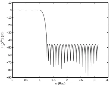
Finally, by using the Parks McClellan approach, the subfiltersHa(z),Hma(z)andHmb(z)can be designed to have magnitude frequency responses as shown in Figs. 9 to 10. Consequently, the magnitude frequency response
0 0.5 1 1.5 2 2.5 3 3.5
−90 −80 −70 −60 −50 −40 −30 −20 −10 0 10
ω (Rad)
|Ha
(e
j
ω)| (dB)
Figure 9. Magnitude Frequency Response of the Digital Subfilter
Ha(z)
of the overall infinite-precision lowpass FRM FIR digital filterH(z)is obtained as shown in Fig. 11.
1) CSD Lowpass FRM FIR Digital Filter GA Opti-mization: The design parameters for the genetic
0 0.5 1 1.5 2 2.5 3 3.5 −90
−80 −70 −60 −50 −40 −30 −20 −10 0 10
ω (Rad)
|Hmb
(e
j
ω)| (dB)
Figure 10. Magnitude Frequency Response of the Masking Digital SubfilterHmb(z)
0 0.5 1 1.5 2 2.5 3 3.5
−120 −100 −80 −60 −40 −20 0 20
ω (Rad)
|H(e
j
ω)| (dB)
Figure 11. Magnitude Frequency Response of the Infinite-Precision Lowpass FRM FIR Digital FilterH(z)
lowpass FRM FIR digital filter, the corresponding CSD FRM seed digital filter is obtained to have a magnitude frequency response as shown in Fig. 12. It can be
ob-0 0.5 1 1.5 2 2.5 3 3.5
−60 −50 −40 −30 −20 −10 0 10
ω (Rad)
|H(e
j
ω)| (dB)
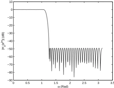
Figure 12. Magnitude Frequency Response of the Lowpass FRM FIR Digital FilterH(z)after CSD Approximation
served that the resulting seed digital filter violates the magnitude response specifications by almost0.5dB in the pass-band, and by almost 20dB in the stop-band region
TABLE III.
DESIGNPARAMETERS FORGA OPTIMIZATION OFCSD LOWPASS FRM FIR DIGITALFILTERH(z)
Design Step Design Parameters
A M= 6, Na= 78, Nma= 22, Nmb= 38
A1 w= 3, WI= 3, WF= 14, B= 12
B pF= 0.8, N= 500
C C= 30
D Nmating= 150, Z= 0.8
E Np= 235
F pM = 0.03
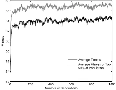
(c.f. Table IV). By applying the proposed GA to the seed FRM digital filter, the GA evolves from one generation to the next with the average fitness of the population pool and the fitness of the top50% individuals as shown in Fig. 13. It can be observed that the trend of the genetic
0 200 400 600 800 1000
52 54 56 58 60 62 64 66 68
Number of Generations
Fitness
Average Fitness Average Fitness of Top 50% of Population
Figure 13. Fitness Evolution for CSD FRM FIR Lowpass Digital Filter
H(z)
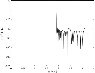
optimization is towards individuals with increased fitness. After 1000 generations, the GA optimization converges to the optimal lowpass FRM FIR digital filter having a magnitude frequency response as shown in Fig. 14. It
0 0.5 1 1.5 2 2.5 3 3.5
−120 −100 −80 −60 −40 −20 0 20
ω (Rad)
|H(e
j
ω)| (dB)
Figure 14. Magnitude Frequency Response of the CSD Lowpass FRM FIR Digital FilterH(z)after GA Optimization
counterpart by 0.01 dB in the pass-band, and by almost 1 dB in the stop-band region (c.f. Table IV).
TABLE IV.
CSD LOWPASSFRM FIR DIGITALFILTERMAGNITUDERESPONSE CHARACTERISTICS BEFORE AND AFTERGA OPTIMIZATION
Multiplier Coefficient Passband Ripple Stopband Loss Representation
Infinite-Precision 0.075dB 41dB CSD before GA
0.65dB 22.05dB Optimization
CSD after GA 0.05
dB 43.62dB Optimization
2) CDBNS Lowpass FRM FIR Digital Filter GA Op-timization: In the case of the GA optimization of the
CDBNS lowpass FRM FIR digital filter, the design pa-rameters are as shown in Table V. The corresponding
TABLE V.
DESIGNPARAMETERS FORGA OPTIMIZATION OF THECDBNS LOWPASSFRM FIR DIGITALFILTER
Design Step Design Parameters
A M= 6, Na= 78, Nma= 22, Nmb= 38
A2 n= 96, m= 69, B= 12bits B pF = 0.8, N= 500
C C= 30
D Nmating= 150, Z= 0.8
E Np= 235
F pM = 0.03
CDBNS FRM seed digital filter is obtained to have a mag-nitude frequency response as shown in Fig. 15, violating the magnitude response specifications by almost 0.046 dB in the passband, and by almost3 dB in the stopband region (c.f. Table VI). By applying the proposed GA to the
0 0.5 1 1.5 2 2.5 3 3.5
−120 −100 −80 −60 −40 −20 0 20
ω (Rad)
|H(e
j
ω)| (dB)
Figure 15. Magnitude Frequency Response of the Lowpass FRM FIR Digital FilterH(z)after CDBNS Approximation
seed CDBNS FRM digital filter, the evolution of the GA from one generation to the next is as shown in Fig. 16. Fig. 17 shows the optimized CDBNS FRM FIR digital filter obtained after 1000 generations, outperforming its infinite-precision counterpart by almost 0.01 dB in the passband, and by almost1dB in the stopband region (c.f. Table VI).
0 200 400 600 800 1000
110 112 114 116 118 120 122
Number of Generations
Fitness
Average Fitness Average Fitness of Top 50% of Population
Figure 16. Fitness Evolution for the CDBNS Lowpass FRM FIR Digital FilterH(z)
0 0.5 1 1.5 2 2.5 3 3.5
−100 −80 −60 −40 −20 0 20
ω (Rad)
|H(e
j
ω)| (dB)
Figure 17. Magnitude Frequency Response of the CDBNS Lowpass FRM FIR Digital FilterHLP(z)after GA Optimization
TABLE VI.
CDBNS LOWPASSFRM FIR DIGITALFILTERMAGNITUDE RESPONSECHARACTERISTICS BEFORE AND AFTERGA
OPTIMIZATION
Multiplier Coefficient Passband Ripple Stopband Loss Representation
Infinite-Precision 0.075dB 41dB CDBNS before GA
0.146dB 37.3dB Optimization
CDBNS after GA 0.06
dB 42.62dB Optimization
B. Design of bandpass FRM FIR digital filters
CSD/DBNS multiplier coefficient spaces.
Passband region 0.15≤w/2π≤0.35
Maximum pass-band ripple ±0.1dB
Lower stopband region 0≤w/2π≤0.145 Upper stopband region 0.355≤w/2π≤0.5 Minimum stopband loss 40dB
From Table VII, the appropriate value for the inter-polation factor M is found to be 8. This renders the
TABLE VII.
FILTERLENGTHS FORBANDPASSFRM FIR DIGITALFILTER FOR VARIOUSVALUES OF THEINTERPOLATIONFACTORM
M Ha Hma Hmb Total Length
2 254 10 6 270
3 168 6 66 240
4 126 56 10 192
5 102 24 26 152
6 84 20 66 170
7 72 272 18 362
8 64 32 56 152
9 56 34 66 156
10 50 506 26 582
11 46 36 114 196
12 42 56 66 164
13 40 200 40 280
14 36 40 272 348
lengths of Ha(z), Hma(z) and Hmb(z) as 64,32 and
56, respectively. Table VIII shows the derived design specifications for the digital subfilters Ha(z), Hma(z) andHmb(z).
TABLE VIII.
BAND-EDGEFREQUENCIES, PASSBANDRIPPLES ANDSTOPBAND LOSSES FORDIGITALSUBFILTERSHa(z),Hb(z),Hma(z)AND
Hmb(z)
Subfilter Passband EdgeFrequencies Stopband EdgeFrequencies Passband StopbandRipple Loss
Ha 0.32π 0.4π 0.085dB 46dB
Hb 0.4π 0.32π 0.085dB 46dB
Hma 0.45πand0.55π 0.29πand0.71π 0.085dB 46dB
Hmb 0.3πand0.7π 0.21πand0.79π 0.085dB 46dB
By using the Parks McClellan approach, the digital subfiltersHa(z),Hma(z)andHmb(z)can be designed to have magnitude frequency responses as shown in Figs. 18 to 19. Fig. 20 shows the magnitude frequency response of the overall infinite-precision bandpass FRM FIR digital filter H(z).
1) CSD Bandpass FRM FIR Digital Filter GA Op-timization: The design parameters for the genetic
opti-mization of the CSD bandpass FRM FIR digital filter are shown in Table IX. Based on the above infinite-precision bandpass FRM FIR digital filter, the corresponding CSD FRM seed digital filter is obtained to have a magnitude frequency response as shown in Fig. 21. Consequently, the resulting seed digital filter violates the magnitude response specifications by almost 2 dB in the stopband region (c.f. Table X). The progress of the proposed GA from one generation to the next is as shown in Fig. 22. After 1000 generations, the GA optimization converges to the optimal bandpass FRM FIR digital filter having a magnitude frequency response as shown in Fig. 23.
0 0.5 1 1.5 2 2.5 3 3.5
−90 −80 −70 −60 −50 −40 −30 −20 −10 0 10
ω (Rad)
|Ha
(e
j
ω)| (dB)
Figure 18. Magnitude Frequency Response of the Digital Subfilter
Ha(z)
0 0.5 1 1.5 2 2.5 3 3.5
−120 −100 −80 −60 −40 −20 0 20
ω (Rad)
|Hmb
(e
j
ω)| (dB)
Figure 19. Magnitude Frequency Response of the Masking Digital SubfilterHmb(z)
0 0.5 1 1.5 2 2.5 3 3.5
−100 −80 −60 −40 −20 0 20
ω (Rad)
|H(e
j
ω)| (dB)
Figure 20. Magnitude Frequency Response of the Infinite-Precision Bandpass FRM FIR Digital FilterH(z)
2) CDBNS Bandpass FRM FIR Digital Filter GA Op-timization: Table XI shows the design parameters for the
TABLE IX.
DESIGNPARAMETERS FOR THEGA OPTIMIZATION OFCSD BANDPASSFRM FIR DIGITALFILTERH(z)
Design Step Design Parameters
A M= 8, Na= 64, Nma= 32, Nmb= 56
A1 w= 3, WI= 3, WF= 14, B= 12
B pF = 0.8, N= 500
C C= 30
D Nmating= 150, Z= 0.8
E Np= 235
F pM= 0.03
0 0.5 1 1.5 2 2.5 3 3.5
−90 −80 −70 −60 −50 −40 −30 −20 −10 0 10
ω (Rad)
|H(e
j
ω)| (dB)
Figure 21. Magnitude Frequency Response of the Bandpass FRM FIR Digital FilterH(z)after CSD Approximation
0 200 400 600 800 1000
66 67 68 69 70 71 72 73 74 75 76
Number of Generations
Fitness
Average Fitness Average Fitness of Top 50% of Population
Figure 22. Fitness Evolution for the CSD FRM FIR Bandpass Digital FilterH(z)
specifications by almost0.08dB in the passband, and by almost 12 dB in the stopband region (c.f. Table XII). Fig. 25 shows the the progress of the proposed GA from one generation to the next. After976generations, the GA optimization converges to the optimal bandpass FRM FIR digital filter having a magnitude frequency response as shown in Fig. 26.
VII. CONCLUSION
This paper has presented a novel genetic algorithm (GA) for the design and discrete optimization of FRM FIR digital filters over the conventional canonical signed-digit (CSD) as well as the emerging canonical double
0 0.5 1 1.5 2 2.5 3 3.5
−100 −80 −60 −40 −20 0 20
ω (Rad)
|H(e
j
ω)| (dB)
Figure 23. CSD Bandpass FRM FIR Digital Filter H(z)after GA Optimization
TABLE X.
CSD BANDPASSFRM FIR DIGITALFILTERMAGNITUDERESPONSE CHARACTERISTICS BEFORE AND AFTERGA OPTIMIZATION
Multiplier Coefficient Values Passband Ripple Stopband Loss Infinite-Precision 0.03dB 50dB CSD before
0.06dB 38.9dB GA Optimization
CSD after 0.045
dB 46.3dB GA Optimization
TABLE XI.
DESIGNPARAMETERS FORGA OPTIMIZATION OFCDBNS BANDPASSFRM FIR DIGITALFILTER
Design Step Design Parameters
A M= 8, Na= 64, Nma= 32, Nmb= 56
A2 n= 96, m= 69, B= 12bits B pF = 0.8, N = 500
C ωp= 0.6π, ωs= 0.61π, k=10..1585, C= 30
D Nmating= 150, Z= 0.8
E Np= 235
F pM= 0.03
TABLE XII.
CDBNS BANDPASSFRM FIR DIGITALFILTERMAGNITUDE FREQUENCYRESPONSECHARACTERISTICSBEFORE ANDAFTER
GA OPTIMIZATION
Multiplier Coefficient
Passband Ripple Stopband Loss Representation
Infinite-Precision 0.03dB 50dB CDBNS before 0.18
dB 28.7dB GA Optimization
CDBNS after
0.038dB 47.2dB GA Optimization
0 0.5 1 1.5 2 2.5 3 3.5 −100
−80 −60 −40 −20 0 20
ω (Rad)
|H(e
j
ω)| (dB)
Figure 24. Magnitude Frequency Response of the Bandpass CDBNS FRM Digital FilterH(z)before GA Optimization
0 200 400 600 800 1000
64 66 68 70 72 74 76 78
Number of Generations
Fitness
Average Fitness Average Fitness of Top 50% of Population
Figure 25. Fitness Evolution for CDBNS FRM FIR Bandpass Digital Filter
0 0.5 1 1.5 2 2.5 3 3.5
−140 −120 −100 −80 −60 −40 −20 0 20
ω (Rad)
|H(e
j
ω)| (dB)
Figure 26. Magnitude Frequency Response of the Bandpass CDBNS FRM Digital FilterH(z)after GA Optimization
developed in terms of a corresponding infinite-precision FRM FIR digital filter, it can be easily modified to begin with a finite-precision FRM FIR digital filter. In the latter case, the number of generations before obtaining an optimal FRM FIR digital filter may increase. The main features of the GA have been demonstrated through its application to the design of lowpass and bandpass FRM
FIR digital filters. It has been shown that the resulting optimized CSD/CDBNS FRM FIR digital filters in some cases outperformed the corresponding infinite-precision FRM FIR digital filters.
ACKNOWLEDGMENT
This work was supported by a Natural Science and Engineering Research Council of Canada (NSERC) under the Discovery Grant#A6715.
REFERENCES
[1] T. Parks and J. McClellan, “Cheyshev approximation for nonrecursive digital filters with linear phase.” IEEE Trans. on Circuit Theory, vol. CT-19, pp. 189–194, 1972. [2] D. C. O. Hermann, L.R. Rabiner, “Practical design rules
for optimum finite impulse response lowpass digital fil-ters.” Bell System Tech. J., vol. 52, pp. 769–799, 1981. [3] Y. C. Lim, “Frequency-response masking approach for
the synthesis of sharp linear phase digital filters,” IEEE Transactions on Circuits and Systems, vol. CAS-33, pp. 357–364, Apr 1986.
[4] H.-J. Kang and I.-C. Park, “Pairing and ordering to reduce hardware complexity in cascade form filter design [digital filters],” ISCAS, vol. 4, pp. 265–268, 25-28 May 2003. [5] R. Hartley, “Subexpression sharing in filters using canonic
signed digit multipliers,” IEEE Trans. Circuits Syst. II, vol. 43-10, pp. 677–688, Oct 1996.
[6] T. Sarmaki and A. Fam, “Subfilter approach for designing efficient fir filters.” IEEE International Symposium on Circuits and Systems, vol. 3, pp. 2903 – 2915, 7-9 June 1998.
[7] Y. C. Lim, “A digital filter bank for digital audio systems,” IEEE Transactions on circuits and systems, vol. 33-8, pp. 848 – 849, Aug. 1986.
[8] S. K. Mitra, Digital Signal Processing - A Computer-Based Approach. NY, NY: McGraw Hill, 2006.
[9] D. L. Yong Ching Lim, Rui Yang and J. Song, “Signed power-of-two term allocation scheme for the design of digital filters,” IEEE Transactions on Circuits and Systems - Analog and Digital Signal Processing, vol. II, pp. 577– 584, May 1999.
[10] B. S. M. Potkonjak and A. Chandrakasan, “Multiple con-stant multiplication: Efficient and versatile framework and algorithms for exploring common subexpression elimina-tion,” IEEE Transactions on Computer-Aided Design, vol. 15-2, pp. 151–165, 1996.
[11] F. A. A. fuller, B. Nowrouzian, “Optimization of fir digital filters over the canonical signed-digit coefficient space using genetic algorithms,” Midwest Symposium on Circuits and Systems, pp. 456–469, Aug. 1998.
[12] V. S. Dimitrov and G. A. Jullien, “Loading the bases: A new number representation with applications,” IEEE Circuits and Systems Magazine, Tech. Rep. 1540-7977, 2003.
[13] S. R. P. Yong Chin Lim and A. Constantinides, “Finite word length fir filter design using integer programming over a discrete coefficient space,” IEEE Transactions on Acoustics, Speech and Signal Processing, vol. ASSP-30, pp. 661–664, Aug. 1982.
[14] T. Sarmaki and Y. C. Lim, “Use of the remez algorithm for designing fir filters using the frequency response masking approach,” IEEE conference on Circuits and Systems, vol. III, pp. 449–455, 1999.
[16] W.-S. Lu and T. Hinamoto, “Optimal design of frequency-response-masking filters using semidefinite programming,” IEEE Transactions on Circuits and Systems, vol. 5, pp. 557–568, Apr. 2003.
[17] ——, “Optimal design of fir frequency-response-masking filters using second-order cone programming,” IEEE Inter-national Symposium on Circuits and Systems, vol. 3, pp. 878–881, May 2003.
[18] D. Suckley, “Genetic algorithm in the design of fir filters,” IEEE Proceedings G., vol. 138, pp. 234–238, April 1991. [19] P. Mercier and B. Nowrouzian, “Design of frm digital filters over the csd multiplier coefficient space employ-ing genetic algorithms,” Proceedemploy-ings of the 2006 IEEE International Conference on Acoustics, Speech and Signal Processing, vol. 3, pp. 968–971, May 2006.
[20] ——, “A genetic algorithm for the design and optimization of frm digital filters over a canonical double base multiplier coefficient space.” Proceedings of 2006 IEEE ISCAS, pp. 3289–3292, May 2006.
[21] Y. C. L. Rui Yang and S. R. Parker, “Design of sharp linear-phase fir bandstop filters using the frequency response-masking technique,” Circuits System Signal Pro-cessing, vol. 17, pp. 1–27, 1998.
[22] D. E. Goldberg, Genetic Algorithms in Search, Optimiza-tion, and Maching Learning. Reading, MA: Addison-Wesley, 1989.
[23] S. Kilambi and B. Nowrouzian, “A novel genetic algorithm for optimization of frm digital filters over dbns multiplier coefficient space based on correlative roulette selection.” IEEE International Symposium on Signal Processing and Information Technology, pp. 228–231, Aug 2006. [24] ——, “A genetic algorithm employing correlative roulette
selection for optimization of frm digital filters over csd multiplier coefficient space,” IEEE APCCAS, vol. in press, Apr 2006.
Patrick Mercier received the B.Sc. degree in electrical and computer Engineering from the University of Alberta, Edmonton, Alberta, Canada, in 2006. He is currently pursuing the M.Sc. degree at the Massachusetts Institute of Technology (MIT) in Cambridge, MA, U.S.A.
His research interests include the design of energy efficient RF and digital circuits and systems for wire-less communication applications. He was the recipient of a Julie Payette Natural Sciences and Engineering Research Council of Canada (NSERC) Postgraduate Re-search Scholarship in 2006.
Sai Mohan Kilambi received the B.Sc. degree in systems and computers engineering with high distinction from the Carleton University, Ottawa, Ontario, Canada, in 2004, and the M.Sc. degree in electrical and computer engineering from the University of Alberta, Edmonton, Alberta, Canada, in 2007.
Currently, he is working as a DSP ASIC/FPGA de-signer at Nortel Networks, Ottawa, Ontario, Canada.
Behrouz Nowrouzian received the B.Sc. degree in electrical engineering from Arya-Mehr (Sharif) University of Technology, Tehran, Iran, in 1975. He received the M.Sc., D.I.C., and Ph.D. degrees from the Imperial Col-lege of Science and Technology, University of London, London, U.K., in 1976, 1977, and 1983, respectively.
He was a member of Micronet, a network funded by Industry and the Federal Government of Canada under the Network of Centres of Excellence (NCE) program from 1991 to 2005.
![Figure 2.Magnitude Frequency Response of the ComplementaryBandedge-Shaping Digital Subfilter Hb (z) [3]](https://thumb-us.123doks.com/thumbv2/123dok_us/8356302.1669023/2.595.314.532.471.562/figure-magnitude-frequency-response-complementarybandedge-shaping-digital-sublter.webp)