Applying Task Modeling and Pattern-based
techniques in Reengineering Processes for Mobile
Learning User Interfaces: A case study
Ana Isabel Molina, Miguel Ángel Redondo, Manuel Ortega
Department of Technologies and Information Systems
University of Castilla – La Mancha
Paseo de la Universidad, 4. 13071 – Ciudad Real. Spain. {AnaIsabel.Molina,Miguel.Redondo,Manuel.Ortega}@uclm.es
Abstract—In the last years there has been a high production
of groupware systems. However, most of these systems have been based on the desktop metaphor. We propose a translation process based on the use of the conceptual model (or, particularly, on the task model and the data model) of the original application. From this model and by means of a pattern-based reengineering process, we obtain mobile versions of the original systems. In this paper the user interface reengineering process is described and an example of the application of patterns for the evolution of a specific system, Domosim-TPC, is shown.
Index Terms—Pattern, Reengineering, Computer Supported
Collaborative Learning, User Interfaces, Mobile Computing
I. INTRODUCTION
There are numerous applications based on the use of computers, which help people solve tasks more easily and faster than before. Their use has been introduced in a lot of areas and. In addition, the hardware supporting these tasks is becoming more and more powerful and versatile [1]. Unfortunately, this is not the case as regards the use of Information Technologies in educational environments, where the introduction of these devices is still slow and the real possibilities of mobility are not exploited (for example, learning at anytime and anywhere).
We believe that the educational environment can be enriched with certain elements that improve the learning process [2]. Among these new devices we should point out PDAs (Personal Digital Assistants). We advocate the introduction of the ubiquitous and mobile computing paradigms in the classroom for educational purposes, and will look at some of the educational benefits its use would provide.
There are a great number of CSCL (Computer Supported Collaborative Learning) systems, whose success and benefits have been contrasted. However, most of them are desktop systems. To make these systems evolve to mobile computing implies a considerable cost and effort. Our objective is to facilitate
the creation of mobile versions of the original systems for designers and developers [3].
We propose a translation process based on the use of the conceptual model (in particular, of the tasks and data models) of the original application. From this model and by means of a reengineering process, we aim to obtain: prototypes of the user interfaces, some completely functional parts of the application (mainly related with the support of cooperative tasks that follows well-known interaction protocols) and code skeletons of the parts that have not been completely specified in the starting application model.
We have taken as a starting point a collaborative e-learning environment based on desktop metaphor [4] and we have studied some tasks, which could be improved through the use of mobile devices like PDAs. For this purpose we have developed an extension of the Domosim-TPC desktop system called Domosim-MOB.
In the following sections we present the reengineering process of the part that is most affected by the change of context: the user interface (UI). For this, firstly, some concepts about tasks modeling are introduced, the phases of the proposed process are described in detail and the role of patterns in each of these steps is shown. Then, an example of application of these patterns to obtain the UI of the Domosim-TPC system is explained. Finally, we show the first results in the evolution process of the asynchronous learning tasks supported in DomoSim-TPC towards PDA devices and we will draw some conclusions and outline the future work we will develop.
II. TASKS-BASED CONCEPTUAL MODELING
The evolution process proposed is based on the task model of the initial applications. The use of task models
for the designing and development of user interfaces is becoming increasingly important, mainly with the aim of obtaining more user-centered interactive applications [5]. There are several methods for tasks analysis, different depending on their level of formalism and purpose (predictive, descriptive and cognitive). Additionally, some notations for simple-user interactive systems modeling have been proposed [6-8]. Some of them have been extended for supporting collaborative applications modeling, or more specifically, cooperative applications [9]. We have selected the ConcurTaskTress (CTT) [7] notation among several studied alternatives because it presents several features that make this option interesting to be used as a conceptual model tool in our proposal:
• Hierarchical representation.
• Graphical notation.
• A wide set of temporary operators.
• Cooperative task modeling.
• It enables patterns specification.
• There is an application (CTTE) for creating, validating and simulating CTT models.
However, this notation has several disadvantages that are enumerated next:
• It allows cooperative tasks modeling, but no modeling of pure collaborative tasks, in which several actors/roles can take part, where the contribution of each to the final product obtained is not obvious.
• CTT does not permit showing the objects of the data model in a graphical mode. Being able to jointly show tasks and data models and their relations, in a same representation, allows us to connect aspects of the presentation layer (interactive tasks) with aspects related with the domain layer of the application. This is a way for connecting the UI design with the rest of the system.
• Although the CTTE tool allows specifying the object manipulated by a task, it does not force us to complete this field. To include this information is vital for our purpose with a view to generate the prototype of the application in a semiautomatic way. UI generation depends, not only on the tasks model and the dialogue (which are graphically expressed in CTT), but also the data model of the application [10].
• CTT does not allow expressing cardinality in the roles or distinguishing between roles and actors (users or devices that can play roles). This notation does not permit modeling the fact that a same actor could play several roles, either. Therefore this notation does not permit modeling the organization supported by the groupware or CSCL tool to be designed; simply it bases the conceptual model on the assignation of tasks to roles. It does not allow representing possible relations between roles (the way use cases can show, where there are subtypes and roles specialization, dynamism of roles, etc.
These disadvantages became limitations with a view to use this notation in our purposes. However, we consider that it is the best option of the existing alternatives, but we take into consideration to extend this notation for solving this problem.
III. PATTERNS-BASED USER INTERFACE REENGINEERING
In the process of adaptation of the traditional system with user interfaces based on the desktop metaphor [11] to other kind of devices, we propose the application of reengineering techniques that facilitate this transition [12]. There is a shortage of methods that make UI migration or improvement easier, that is, that help in re-design and re-implementation processes [13]. We propose the use of interaction patterns as a support tool in the proposed reengineering process. A pattern describes a contrasted solution to a recurrent problem in a specific context [14]. One of the most important features of patterns, which justifies its use in our adaptation process, is that a pattern is a platform- and implementation-independent solution.
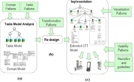
Commonly, the use of patterns in HCI (Computer Human Interaction) area has been to lead and assist UI design processes. We propose applying patterns in several phases in the interface reengineering process (see figure 1).
Figure 1. User Interface Reengineering Process Phases
Next, these phases are detailed:
agree with the problem solved by any of the proposed patterns.
(b) Evolution (see figure 1.b). This phase consists in redesigning the UI model for adapting to new platform restrictions or context of use. In this phase as well, transformation patterns are used in order to obtain a modified model from the original one. This implies taking into account the capacities of the new platform, mainly visualization and power aspects.
(c) Direct Engineering (see figure 1.c). Starting from the tasks model obtained in the previous phase we obtain the new IU adapted to different devices. A detailed explanation of this last phase is presented in [15].
A. Mapping process
The mapping process (well-known as the “mapping problem” [16]), consists in going from an abstract representation of the system (the task model) to a concrete representation (dependent on the final platform and on the widgets supplied by the toolkit used for developing the UI).
When we deal with the evolution of an application (in particular, the user interface) towards devices with limited interaction capacities (mobiles phones, PDAs,…) or new interaction modes (tactile screen, use of pen for pointing), the mapping problem is more complex, and especially, so is a possible generalization. The transformation process must take into account device restrictions, but without constraining the application usability in the adaptation process to the new context. Selecting the best interaction element (or widget), as well as the arrangement of them in the screen area, is becoming the main problem to be solved. The user interface development is a very subjective process, which depends a lot on the designer’s experience, creativity and aesthetic opinions. Complete generalization of this process is complex and, in fact, there is not much success in this sense. Normally, developed applications are very closed in specific domains. Several systems have attempted to automatically generate user interfaces in a model-based environment (UIDE [17], Mecano [18], Trident [19]). The idea of these systems was to try to automate as much as possible the interface generation process from a task model. However, these systems usually delegate to the designer the responsibility of selecting the interface final appearance. The system assists about possible alternatives applicable to a certain case.
IV. THE DOMOSIM-TPC ENVIRONMENT
The main goal of the work which this article is situated is to incorporate the mobile computing paradigm in the teaching and learning of domains with a high experimental degree in order to take into account mobile computing possibilities. Also, the features of these domains provide an excellent framework to analyze the collaborative process. Thus, we are going to study the
methods that allow us to systematize these tasks. We will take as a starting point a collaborative e-learning environment based on the desktop metaphor, following the named “Domosim-TPC [20]”. To achieve our goal, we analyse the tasks which are susceptible of improvement through mobile computing. The aforementioned system is used to support the learning of the design of automated control facilities in buildings and housing, also called Domotics. The term Domotics is associated to the set of elements that, installed, interconnected and automatically controlled at home, release the user from the routine of intervening in everyday actions and, at the same time, they provide optimized control over comfort, energetic consumption, security and communications.
Using the DomoSim-TPC system, the activities of practical learning of domotical design are structured in three clearly differentiated stages (figure 2). In each of them diverse cognitive exercises are carried out and approached and representations of expert knowledge are used.
Figure 2. Stages and Tasks of Domotical Design Learning carried out in an experience with Domosim-TPC
The collaborative planning of domotical design is divided in several phases, supported in three different workspaces:
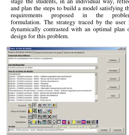
• Individual Planning workspace (figure 3). In this stage the students, in an individual way, reflect and plan the steps to build a model satisfying the requirements proposed in the problem formulation. The strategy traced by the user is dynamically contrasted with an optimal plan of design for this problem.
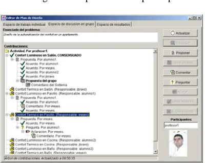
• Discussion Workspace (figure 4). The discussion process is a social task in which participants in an activity reflect about the model built, exchange ideas, propose a resolution mechanism, acquire new knowledge and purify their contributions. From this process a proposal (model) is obtained, reflecting the viewpoint of each participant.
Figure 4. Discussion workspace in Domosim-TPC
• Result workspace. Finally, the space of results facilitates the visualization and perception of the parts of the activity that the group has already developed and agreed. The participants can observe the results and solutions obtained during the process, independently of the discussion and of the development process necessary for their achievement (this is the main goal of a groupware tool). Alike the discussion space, the results space has a tree-shaped hierarchical structure, used to organize the information relative to the results obtained in the activity. The application allows visualizing the results in a textual and a graphical way.
We are interested in the effective use of such mobile computing devices for collaborative learning. There are tasks in the system Domosim-TPC which are susceptible of improvement through mobile computing. In particular, the Collaborative Planning of Design is a asynchronous and reflexive task which could be improved using mobile devices.
V. GENERATING USER INTERFACES PDA-BASED TO THE DOMOSIM-TPC SYSTEM
Domosim-TPC is based on the desktop metaphor and use direct manipulation as an interaction paradigm. However, some tasks supported by this tool can be more real and accessible if tackled including features of mobile computing. This mobile version of Domosim-TPC has been called Domosim-Mob [21].
The arrangement of the elements in the user interface (mainly when we are talking about devices with small-sized screens) means having the guidelines application into account, as well as knowing the relation between the tasks supported by the user interface. Using a concrete widget, dividing a task in subtasks or the activation/deactivation of the components in the user
interface will be influenced by these aspects. The new context of use implies to reconfigure the user interface [22]. We can use several methods for it: Redistribution of widgets along several windows or tabs; Using a reduced version of a widget, using a scrollable version or one that could be hidden by the user; Using a less sophisticated version of the widgets, etc.
Techniques for selecting the most appropriate widget when we have certain screen resolution restrictions have been researched by other authors [23], but it is still a difficult problem to be faced and generalized.
VI. ANALYZING AND MODELING TASKS USING CTT
In this section, we describe the analysis of the main tasks in asynchronous workspace supported in Domosim-TPC. This analysis should be done at a low level. It has to determine the kind of interaction task (for example, enter text, select a Boolean value, select a numeric value) and the kind of domain application objects manipulated by the tasks. This information facilitates the identification of the visual component (widget) that best allows the realization of a particular task, taking target device restrictions into account. The logical decomposition of tasks is also reflected in the selection, consistency and grouping of elements in the GUI obtained.
Figure 5 shows the task model in CTT notation for individual planning. Figure 6 shows details about the abstract task called PLANNING.
Figure 5. Tasks modeling of space for individual planning in Domosim-TPC.
Figure 6. Modeling of abstract task PLANNING
Diagram in figure 5 shows the general functions that can be performed on the design plan. It can be shown graphically. There are two modes of visualization: a list of nodes (a node represent a action) connected by arcs (representing precedence relationships); and the design of the scene that is created for executing the planned actions list. We can also save the design plan. The option Clear eliminates all the information contained in the actions list. These actions are applicable to the plan design object. These must appear in the user interface next to the object related (the list box that shows the sequence of steps in the plan).
In addition, the individual plan editor handle design action objects. In the diagram shown in figure 6 the
actions Add_DESIGN_ACTION and
Delete_DESIGN_ACTION are included. The first one has certain complexity. When a task (that means an operation over a internal object) is of the interaction type, the mapping to a perceptible object (a widget in the interface) is more direct. This kind of operations can be represented by means of buttons, options in a menu or a contextual menu. It has been applied to the mapping of the
Delete_DESIGN_ACTION operation, or the
aforementioned generic functions, which the user can perform on the DESIGN_PLAN object.
VII. APPLYING PATTERNS IN THE PROCESS OF USER INTERFACE GENERATION ADAPTED TO DEVICES
In last phase in the reengineering process (obtaining the new user interface) we are going to use patterns for selecting the best visualization technique, depending on the concrete device for which the user interface is generated. Each pattern determines what the best presentation technique for supporting a specified task is.
Each pattern must take into account the specific platform with which the user interact (there are presentations for desktop applications, which are not suitable when we interact with a mobile phone, whose screen size and resolution are smaller). For example, for showing the progress of a task we can use a progress bar, the transfer ratio, remaining time, etc.., in a dektop application, while in a PDA device we must use a less sophisticated visualization technique, such as the task percentage, which reduces the use of screen space.
A. Example of Patterns Application for Generating the Domosim-Mob User Interface
This section shows an example of the application of a visualization pattern for evolving Domosim-TPC. In particular we have made the part dedicated to collaborative planning of design evolve. This consists of asynchronous tools in part intended to be used by the student, and it gives support to the Domosim-TPC system.
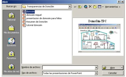
In all the workspaces in Domosim-TPC a recurrent problem is detected: there is a structure (an aggregate), which must be shown. This object consists of a set of elements that can be visualized in several modes. In the case of the discussion workspace, there is an aggregate (the conversation) consisting of contributions, which can be visualized in an individual mode. In individual and result visualization workspaces, the aggregate is the activity to perform, composed by a set of elements that can be created or visualized (the epigraphs). Another similar example is shown in the dialogue for performing an action (open or save) over a file (see figure 7). The user interface that supports these tasks has a similar appearance as shown next:
Figure 7. Dialogue window for opening a file
In this case there is an aggregate (a directory) of elements (files). One of them can be selected, and this one can be visualized in a certain mode in the UI. The same case is shown in e-mail management systems (Microsoft Outlook) or systems for visualizing news (Forte Agent). This is a recurrent problem, which causes a concrete kind of visualization (normally in tree mode), and therefore, it is a visualization pattern candidate. The pattern structure can be as follows:
Problem: The user needs to search along the elements that form an aggregate, select one of them and visualize it.
Solution: It will change depending on the concrete platform and the nature of the element to be visualized (visualization mode). Thus, the next choices can be considered:
tree widget to show this situation. In both cases elements must be selectable. The window part devoted to visualization must be specialized in the visualization of the kind of specific information (textual, graphical, …).
Figure 8. UI for supporting aggregate and components visualization without space restrictions
• In the case of having space restriction, the first two components (aggregate and elements list) must appear together in a window. Another window is necessary for visualizing the selected element (for example, a large text or an image or a graphic of a certain size) (see figure 9).
Figure 9. UI for supporting aggregate and components visualization with space restrictions
This visualization pattern has been used for generating the PDA version of each of the Domosim-TPC workspaces aforementioned. The PDA version for discussion workspace is shown in figure 10. On the left (see figure 10.a) the aggregate is shown (the conversation). This aggregate is composed by a set of contributions made by the participants in an activity andorganized in a hierarchical way (by means a tree). A contribution can be selected to be visualized in detail (figure 10.b).
Figure 10. PDA user interface for supporting discussion
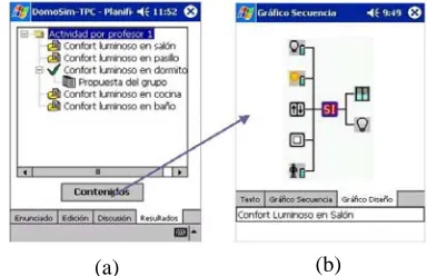
The PDA version for results visualization is shown in figure 11. The main objective of the space of results is to facilitate the visualization and perception of the parts of the activity that the group has already developed and agreed. Alike the discussion space, the result space has a tree-shaped hierarchical structure (figure 11.a), used to organize the information relative to the results obtained in the activity. Selecting some of the node leaves or nodes that represent solutions to an epigraph, the dialog in figure 11.b displays the actions that constitute the design plan corresponding to the marked node solution.
(b) (a)
Figure 11. PDA user interface for results visualization
VIII. DOMOSIM-MOB: A PDA-BASED APPLICATION FOR DOMOTICAL DESIGN LEARNING
The system Domosim-Mob has been obtained as result of applying the aforementioned method for generating the PDA User Interface version of the Domosim-TPC system.
It is important to point out that the functionality supported in PDA devices is a supplement of the original system. Domosim-Mob is an extension developed to add mobility to the learning process (“learning anywhere and at anytime”). Whilst mobility in learning processes favours the involvement of students in the task in question, the use of these devices does, however, mean paying the price of visualization limitations.
The tasks supported in Domosim-Mob are similar to Domosim-TPC tasks, but the access to them has been improved, as a consequence of there being greater flexibility. However using mobile devices, beside the features characteristic of the discussion process, creates additional problems due to the fact that it offers the possibility of participating in the discussion without the need for the device to be connected to the server: that is the synchronization with the rest of the members in the group. One-to-one synchronization, in other words, synchronization of a mobile device with the system, is quite well resolved. However, in our case a synchronization of order n to m is necessary. Our approach to solving the problem is by applying a variation of the Schiper-Eggli-Sandoz algorithm [24] for the exchange and ordering of messages in distributed systems respecting a causal order based on a model of logic clocks.
A. Design and implementation aspects
In this section some design and implementation aspects of Domosim-Mob are looked at: its structure and the work modes it supports.
To create the Domosim-Mob application we have chosen Visual Studio .NET as the development platform and C# as the programming language. In principle the possibility of using Java was considered, but finally we opted for using .NET mainly due to the lack of efficiency of Java/Swing (using Jeode as the virtual machine). Besides using AWT we did not have sufficiently advanced widgets. The main causes of our language choice were efficiency and visualization issues.
B. The Domosim-Mob Structure
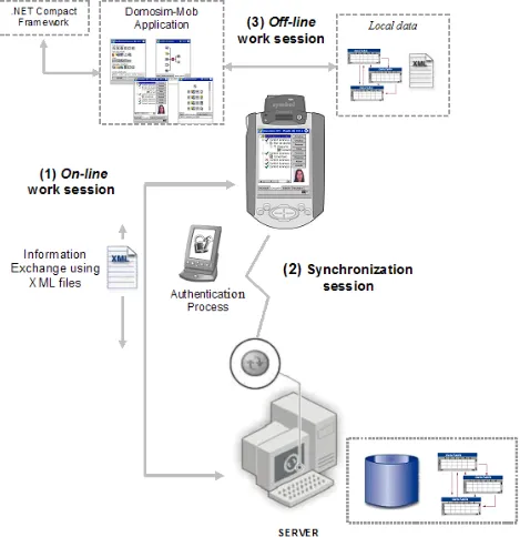
The diagram in figure 12 shows the global structure of the Domosim-Mob application. The new context of use entails the appearance of several work modes in the application:
• Connected work session (Figure 12-1). The mobile application accesses the information server, although not at the same time as other participants of the group. The information associated with the group process and the history of the group is recorded and filed at a central location. Information exchange is based on XML files.
• Disconnected work session (off-line) (Figure 12-2), in which the user works with local information available in the mobile device. Students can work in isolation. They reflect on and construct the solution of the problem, which is stored in the PDA.
• Synchronization session (Figure 12-3). This one appears as a result of the previous work mode. Students send updated information to the server (individual contributions in the discussion process and their answer to the proposed problem) with the aim of providing and storing consistent information about the collaborative experience. The server distributes this information to the rest of the members of the teams. In order to guarantee confidentiality when accessing the server, an authentication process is necessary.
Figure 12. General structure of Domosim-Mob
IX. CONCLUSIONS
Using patterns is an interesting tool for reengineering because the same pattern can be implemented in several ways in several platforms (PDA, mobile phones, etc). We have proposed using patterns in all phases of the user interface reengineering process: for analysing (reverse engineering phase), for redesigning (transformation phase) and for generating code (direct engineering phase). For illustrating their use and as study case we have applied them for making Domosim-TPC system evolve towards mobile computing. Now we propose completing these patterns, validating it and applying it to other systems.
ACKNOWLEDGMENT
This work has been partially supported by the Junta de Comunidades de Castilla – La Mancha in the project GAMTest (PCI-05-005).
REFERENCES
[1] M. Sharples. “Disruptive Devices: Personal Technologies and Education”, in Educational Technology Research Paper Series 11. Birmingham: The University of Birmingham. 2000
[2] E. Soloway, C. Norris, R. Blumenfeld, B. Fishman, J. Krajcik, and R. Marx, "Log on Education: Handheld devices are ready-at-hand," Communications of the ACM, 44 (6), pp. 15-20, 2001.
[3] A. I. Molina, M. A. Redondo , and M. Ortega, "Evolution of an e-Learning Environment based on Desktop Computer to Ubiquitous Computing," presented at 34th Frontiers in Education IEEE Conference (FIE 2004), Georgia (EEUU), 2004.
[5] F. Paternò, Model-Based Design and Evaluation on Interactive Applications: Springer Vergal, 1999.
[6] J. Annett and K. D. Duncan, "Task Analysis and Training Design," Occupational Psychology, vol. 41, pp. 211-221, 1967.
[7] F. Paternò, "ConcurTaskTrees: An Engineered Notation for Task Models.," in The Handbook Of Task Analysis For HCI, D. Diaper and N. A. Stanton, Eds. LEA, Mahwah, NJ.,, 2004, pp. 483-501.
[8] R. Harstson and P. Gray, "Temporal Aspects of Tasks in the User Action Notacion," Human Computer Interaction, vol. 7, pp. 1-45, 1992.
[9] F. Paternò, C. Santoro, and S. Tahmassebi, "Formal model for cooperative tasks: Concepts and an application for en-route air traffic control.," presented at 5th Int. Workshop on Design, Specification, and Verification of Intractive Systems DSV-IS '98, Abingdon, 1998.
[10] C. Pribeanu, "Investigating the relationship between the task model and the design model in a task-based approach to user interface design," presented at 1st International Workshop on Task Models and Diagrams for User Interface Design - Tamodia 2002, Bucarest, 2002.
[11] B. Schneiderman, Designing the User Interface. Strategies for Effective Human-Computer Interaction: Addison Wesley Professional, 1997.
[12] Carnegie, "Perspectives on Legacy System Reengineering.," Carnegie Mellon University 15213-3890, 1995.
[13] R. S. Arnold, "Software Reengineering," IEEE Press, 1992.
[14] E. Gamma, R. Helm, R. Johnson, and J. Vlissides, Design Patterns: Elements of Reusable Object-Oriented Software: Addison Wesley, 1995.
[15] A. I. Molina, M. A. Redondo, and M. Ortega, "Analyzing and modelling user task in DomoSim-TPC system for adapting to mobile devices," in HCI related papers of Interacción 2004, R. Navarro and J. Lorés, Eds.: Springer-Verlag, 2005, pp. 221- 241.
[16] Q. Limbourg and J. Vanderdonckt, "Addressing the Mapping Problem in User Interface Design with UsiXML." TAMODIA’2004, Prague, ACM Press. 2004 [17] Foley, J., et al., "UIDE-An Intelligent User Interface
Design Environment", in Intelligent User Interfaces. 1991: p. 339-384.
[18] Puerta, A.R. "The MECANO Project: Comprehensive and Integrated Support for Model-Based Interface Development". in CADUI96: Computer-Aided Design of User In-terfaces. 1996. Numur, Belgium.
[19] Vanderdonckt, J.M. and F. Bodart. "Encapsulating Knowledge for Intelligent Automatic Interaction Objects Selection". In InterCHI'93. 1993: ACM Press.
[20] Redondo, M.A., (2002). Collaborative planning of design in simulation environments for distance learning. Doctoral Thesis. ProQuest Information and Learning, USA. [21] A. I. Molina, M. A. Redondo, and M. Ortega, "A system to
support asynchronous collaborative learning tasks using PDAs," Journal of Universal Computer Science., 2005. [22] J. Eisenstein, J. Vanderdonckt, and A. Puerta, "Adapting to
mobile contexts with user-interface modeling.," presented at IEEE Workshop on Mobile Computing Systems and Applications WCSMA'2000, Los Alamitos (Monterey), 2000.
[23] J. Eisenstein and A. Puerta, "Adaptation in Automated User-Interface Design," presented at IUI'2000, New Orleans, 2000.
[24] A. J. Aguilar, F. Jurado, and M. A. Redondo. "Un algoritmo de ordenación causal de mensajes para aplicaciones educativas colaborativas que utilizan dispositivos móviles con redes inalámbricas". In procc. of 1st Spanish Congress of Computer Science (CEDI-Sintice). 2005
Ana I. Molina, received her Computer Science (2002) degree and his PhD (2007) from University of Castilla – La Mancha (Spain). She is joined the Computer Science and Software Engineering Faculty of University of Castilla – La Mancha. In addition to teaching, her main interests are in the field of New Information Technologies applied to collaborative learning and computer-human interaction.
Miguel A. Redondo, received his Computer Science (1997) degree from University of Granada (Spain) and his PhD (2002) from University of Castilla – La Mancha (Spain). He is joined the Computer Science and Software Engineering Faculty of University of Castilla – La Mancha. In addition to teaching, his main interests are in the field of New Information Technologies applied to collaborative learning and computer-human interaction.