The Investigation of Die Back
Edge Cracking in Flip Chip
Ceramic Ball Grid Array Package
(FC-CBGA)
Zainudin Kornaina, Azman Jalara, Rozaidi Rasidb, aInstitute of Microengineering and Nanoelectronics (IMEN) bSchool of Applied Physic, Universiti Kebangsaan Malaysia
43600 UKM, Bangi, Selangor, Malaysia
Abstract
The cracking between die back edge and top fillet for Flip Chip Ceramic Ball Grid Array (FC-CBGA) package due to thermal cycling have been investigated in this study. Finite Element Analysis (FEA) model was used to analyze the effect of fillet geometry and material properties of underfill upon stresses along the die back edge. The thermo-mechanical properties of commercial underfill were obtained by using Thermal Mechanical Analyzer (TMA) and Dynamic Mechanical Analyzer (DMA) as the input for the simulation. Die stress distribution for different fillet height and width were generated to depict variation of stress due thermal loading and the variations of tensile stress were discussed for parameter optimization. The effect of different underfill material properties were discussed as well for thermal stress reliability improvement.
1 INTRODUCTION
Flip chip method becomes popular technology in electronic packaging industry because of small package size and high electrical performance. However, in order for flip chip technology to become more popular, there are several hurdles to overcome, for instance, assembly cost and reliability issues. The cost issue is the most critical parameter among them. Therefore, the trend is that substrate material for flip chip changes from ceramic to organic due to cost issue. However, ceramic substrate (FC-CBGA) offers better moisture resistance, electrical insulating property and higher thermal conductivity than organic substrate (FC-PBGA) and still relevant until now especially for high-reliability commercial applications like CPU [1].
Management of thermo-mechanical stress and improvement of moisture susceptibility are key challenges in reliability assessment of FC-PBGA. The thermo-mechanical stresses are mainly induced by large Coefficient Thermal Expansion (CTE) mismatch between silicon die and organic substrate which cause the typical failure mode such as underfill and die cracking, interface delamination and solder fatigue cracking [2]. An application of ceramic substrate has lower risk failure especially underfill crack underneath the die area due to lower CTE mismatch between die and substrate as compared to organic substrate [3].
Underfill cracking can be categorized into three groups such as popcom cracking, underfill corner cracking, and underfill edge cracking which can lead to die edge cracking [4]. The popcom and corner cracking in underfill were originated from interfacial delamination between underfill and die passivation [4]. Since the mechanism of die edge cracking due to thermal loading or temperature cycle test (TCT) was very complicated, mechanical simulations and experiments were conducted and studied elsewhere [5]. The die edge cracking was closely related to the local CTE mismatch between underfill material and silicon die. Die edge cracking can be eliminated by using low CTE underfill material and by the control of underfill fillet size [4]. It also suggested that to avoid die edge crack issue during TCT, the thickness of die and substrate should be changed in order to reduce the package warpage [6]. In addition, the stiffness should be attached on the backside of silicon die to release the stress.
die. Fillet geometry variability is the result of the underfill dispensing process and the materials involved. Underfill is usually dispensed on one or two adjacent sides of the die. Capillary flow is utilized to fill the gap between die and substrate, in the presence of flip chip bumps where the viscosity, surface tension and contact angle are key material properties [5]. The interaction of the substrate and underfill affects the fillet formation. Differences in surface roughness, cleanliness, solder mask properties on the substrate and passivation properties on the silicon die could result in very different fillet geometries for the same underfill. Lim et al. [6] attempted to quantify the effect of underfill fillet on flip chip package reliability for ceramic flip chip packages with wafer level underfill for a standard die. For ceramic packages the underfill delamination jeopardy is less due to closely matched coefficients of thermal expansion of the ceramic substrate and the silicon die. Therefore the failures after reliability test such as thermal cycling loading are very rare happened. Recently, it was found in industry the crack occurred at die back edge adjacent to top fillet that propagated to active area due to thermal stress in FC-CBGA.
In this paper the thermal stress-analysis using FEA was carried out to investigate the source of die back edge crack occurred between die edge and underfill top fillet of package FC-CBGA due to thermal cycling reliability test (-55oC/125 oC) at 500 times cycle. Package with different underfill’s thermo-mechanical
properties material such as the CTE, Young’s modulus and the glass transition temperature (Tg) have been simulated to find improvement of die back edge reliability.
2 METHODOLOGY
2.1 Underfill Bulk Analysis- Data Properties for Simulation
Material analysis using dynamic mechanical analysis (DMA) and thermo-mechanical analysis (TMA) have been conducted for obtaining underfill material’s properties [7]. Linear thermal expansion coefficient of cured samples was measured from -50oC to 260oC using a TA Instrument thermal
mechanical analyzer operated in expansion mode. Cylindrical samples with a typical sample height of approximately 4.7 mm were cured at 165oC at 60
minute. TMA data were obtained at a heating rate of 58oC/ min. To minimize
viscous flow during the measurements especially above the glass transition temperature Tg, all TMA measurements were performed with a small loading force of 5 mN.
measurements were carried out on a TA Instrument dynamic mechanical analyzer operated in rectangular tension mode. The dimension of cured sample was 15.0 mm x 12.9 mm x 1.20 mm. During DMA experiments, the static force was kept at 120% of the dynamic force and the frequency of the dynamic force was maintained at 1 Hz. The result of TMA and DMA analysis is shown in Table 1.
Table 1 : DMA and TMA properties for all components of FC-CPGA
Component DMA Modulus (GPa) CTE 1/2 (ppm/oC) TMA Tg (oC)
Die 131 2.8
-Underfill Refer to TABLE 2
Ceramic Substrate 75 12.3
-2.2 Reliability test for unit package
The package was based on Hi-CTE ceramic substrate with size of 33mm x 33mm and thickness of 1.2 mm. The die attached to the substrate was a flip chip with 1023 inputs/outputs and has size of 14.5mm x 11.9mm and thickness of 0.75mm. The flux used was a clean type; reflow has been performed under an N2 atmosphere. The commercial underfill from Ablestik was used for filling the gap between die and substrate by using conventional capillary flow dispenser. The 2D dimension of the package assembly is given in Figure 1. For evaluating assembly reliability, temperature cycling with a two-chamber air-to-air test (ATC) between -55oC and 125oC for 500 cycles has been performed
and the failure observation was executed by using C-Mode Scanning Acoustic Microscope (C-SAM). Since the package was ceramic substrate, the preconditioning test (Moisture Sensitivity Level Test) was not necessary. Die
Through C-SAM inspection, it was found the unit with die edge crack after 500 cycles thermal loading. Figure 2 shows the position of the die edge crack. The source of die crack has been investigated by using finite element analysis (FEA) simulation.
Figure 2 : Die edge crack detected in package after 500 times thermal cycling test
2.3 Finite Element Modeling
(a)
(b)
Figure 3 : (a) Quarter Symmetric FE model of FC-CBGA (b) Details of fillet configuration [3]
0.25mm 0.75mm 1.25mm 1.75mm 2.25mm Figure 4 : Schematic diagram for fillet width and angle geometry at 100% fillet
height
Three different combinations of CTE and Young's modulus also were used to observe the effect of material properties against thermal stress distribution. 100% fillet height and 1.61mm fillet width was assumed for all materials.
While two CTE values before and after the glass transition temperature Tg, CTE1 for T < Tg and CTE2 for T > Tg, are usually provided by experimental results for polymer materials, the ANSYS definition of the mean or effective expansion coefficient was used for the implementation:
1 2
2 2
1
1) ( )
(
T T
CTE Tg T CTE T Tg Eff.CTE
− − + −
=
(1)
where T2 is the stress-free or reference temperature of the component being modeled [7]. As T1 was a -55oC and T2 was the underfill’s curing temperature
Table 2 : Thermo-mechanical properties of underfill for FEA input Underfill DMA E (GPa) CTE1/CTE2
(ppm/C) TMA Tg (oC) Eff. CTE (ppm/oC) E x CTE
Ablestik 9.7 29.3 / 92.8 102.35 47.4 459.78
Henkel 10.1 25.4 / 85.4 105.82 41.5 419.15
Nagase 5.9 34.8/126.2 97.5 61.36 362.02
3 RESULT AND DISCUSSION
3.1 Effect of Fillet Height of Underfill
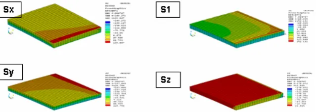
The die was detached from the global model to observe the die back stress distribution only. Figure 5, 6 and 7 show the thermal shear stress distribution at the die back for fillet height of 100%, 75% and 50% respectively. From the simulation results the highest shear stresses were always found at the edge of die. For 100% fillet height (Figure 5), the in-plane normal stresses Sx and Sy were tensile at die back center, and are highest near edges. The out-of-plane normal stress Sz was near-zero at die back center, but becomes tensile near edges. The maximum principal stress S1 was tensile at die back center, and was highest near corners. Correlating with actual observation, die cracks are more likely to happen near edges due to higher tensile stress. This stress was believed can lead delamination at the interface between underfill fillet and die. Later the delamination was propagated to die edge and initiated the crack [7].
Figure 5 : Die stress distribution for fillet height 100%
Figure 6 : Die stress distribution for fillet height 75%
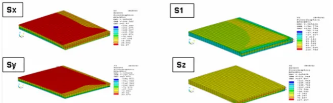
For 50% fillet height (Figure 7) all stress distribution pattern showed the same as Figure 5 and 6 for in/on plane normal stress and maximum principal stress but this fillet height giving lower tensile stresses that that of 75% and 100% fillet height.
Figure 7 : Die stress distribution for fillet height 50%
Figure 8 : Location of interest in underfill fillet area [3]
For further analysis the tensile stress variation with fillet height coverage for principal stress S1 was plotted as depicted in Figure 9. It was clearly demonstrated the highest stress occurred at the corner and edge of die where decreases the fillet height will decreases the maximum stress.
Path from die center to corner for S1 stress plots -20 0 20 40 60 80 100 120 140
0 2 4 6 8 10
Distance from Die Center to Corner (mm)
M ax im um Pr in ci pa l Str es s S1 (M Pa )
25% Fillet Height 50% Fillet Height 75% Fillet Height 100% Fillet Height
Figure 9 : Tensile stress variations with different fillet height (1.61mm fillet width)
3.2 Effect of Fillet Width of Underfill
Figure 7. Lei et al. [9] mentioned that when the fillet angle was decreased, the energy release rate was significant released.
0 20 40 60 80 100 120 140 160 180
0.25 0.75 1.25 1.75 2.25
Fillet Width (mm)
M ax im um T en si le Str es se s (M Pa )
Normal Stress Sx Principal Stress S1
Figure 10 : Maximum tensile stress with different fillet width (100% Fillet Height)
3.3 Effect of Underfill Material Properties
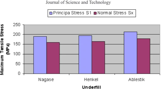
Figure 11 : Maximum tensile stress with different underfill material
4 CONCLUSION
This study has presented a FEA simulation based, comparison in underfill fillet geometry and underfill material properties in investigation the die back edge cracking in FC-CBGA package. The results indicate that:
The die edge crack due the higher tensile stress existed especially in the die corner and edge which interfacing with the top underfill fillet
The die edge crack can be avoided by making the fillet height lower and fillet width/contact angle smaller.
The risk of high tensile stress at die can be reduce by using underfill material which has low multiplication of E modulus and CTE (E x CTE)
ACKNOWLEDGEMENT
The authors would like to thank Freescale Semiconductor (M) Sdn. Bhd., Malaysia for giving support of package preparation and reliability test as well as FEA consultancy.
REFERENCES
[1] Ken, G. 2001. Area Array Packaging Handbook Manufacturing and Assembly, First Eds., McGraw-Hill International.
[3] Karan, K,. Sidharth., Ajit, D., Charlie, J.Z., Richard, C.B. 2006. Impact of Underfill Fillet Geometry on Interfacial Delamination in Organic Flip Chip Packages, Electronic Components and Technology Conference : pp. 1604-1610
[4] Jong, B.S., Em, .C.A., Tae, J.C., Ho, J.M., Tae, G.C. 2000. Mechanisms of Die and Underfill Cracking in Flip Chip PBGA Package, International Symposium on Advanced Packaging Materials : pp. 201-205
[5] John, W, 2002 . Underfill of Flip Chip on Organic Substrate: Viscosity, Surface tension, and Contact angle, Microelectronics Reliability, Vol. 42, pp. 293-299
[6] Lim. N & Hwang. N, 2002. Effect of Underfill fillet configuration on Flip Chip Package Reliability, IEEE Internationall Electronic Manufacturing Symposium, pp. 291-303
[7] Yi, H, Brian, E.M., Alan, O, Stacy H.N., Christine, B, John, F.B. 2000. Thermal characterization of an epoxy-based underfill material for flip chip packaging, Themochimica Acta, Vol. 8, pp. 357-358. [8] Shim, K.W., &, Wai, Y.L. 2006. Solder Fatigue Modeling of
Flip-Chip Bumps in Molded Packages, International Electronic Manufacturing Technology Conference, pp.109-114
[9] Lei L. Mercado, Vijay, S. 2000. Evaluation of Die Edge Cracking in Flip-Chip PBGA Packages, Inter Society Conference of Thermal Phenomena, pp. 73-78
[10] Fan, X.J., Wang, H.B & Lim, T.B. 2001. Investigation of the Underfill Delamination and Cracking in Flip-Chip Modules under Temperature Cyclic Loading, IEEE Transaction Components and Pkg


![Figure 7. Lei et al. [9] mentioned that when the fillet angle was decreased, the energy release rate was significant released.](https://thumb-us.123doks.com/thumbv2/123dok_us/8444488.1702660/10.595.127.465.202.396/figure-mentioned-fillet-decreased-energy-release-significant-released.webp)