Infogain Publication (Infogainpublication.com) ISSN: 2454-1311
Energy-Lifetime Control Algorithm for
Variable Target Load Demands of Ad Hoc
Networks
Amir J. Majid
Ph.D., College of Engineering, Ajman University of Science & technology, UAE
Abstract— The energy and lifetime of Ad hoc wireless
sensor-target networks are improved using load control algorithm with different parameters and coverage load in demand, as well as sensor-target configurations. The main goal is to increase the lifetime of sensors by selecting appropriate sensor subsets to satisfy the minimum required value of overall coverage failure probability. The algorithm investigates the different sensor subsets, according to their coverage failure probabilities, and varying intervals of target load demands.
Keywords— Algorithm, Lifetime-Energy, Target Demand, Variable Load, Ad Hoc, Failure Probability.
I. INTRODUCTION
Wireless sensor networks (WSN) are widely used in home and industrial applications alike, but suffering from short lived energy and lengthy and extended lifetime [1]. Therefore Ad Hoc networks lifetime and power are the two most important issues related to these wireless sensor network, beside an adequate target coverage.
The interfacing of normally large number of neighboring nodes in WSN with each other in numerous routes, as well as consuming large transmission power, can limit network lifetime and performance. Target zones coverage utilization can be improved either by deploying sensors to cover sensing zones completely, or make sure that all zones are covered by a certain number of sensors, such as one-coverage or k-one-coverage [2][3], or select active sensors in a densely deployed network to cover all zones [4][5][[6][7][8]. The last case of such literature is known as an Activity Scheduling Problem (ASP) [9][10], which is divided into four classes: area, barrier, patrol or target coverage.
Previous work attempts were proposed aiming to organize sensors in a number of subsets, such that each set completely covers all zones, thus enabling time schedules for each subset to be activated at a time, thus removing redundant sensors which may waste energy and consequently reduce network lifetime [11]. In the literature many algorithms are proposed such as generic, linear programming, greedy algorithms [12][13][14][15][16]. One
important technique is to improve reliability in cases when sensors may become unavailable due to mobility, physical damage, lack of power or energy malfunctioning. This problem has been addressed in the literature before; namely the α-Reliable Maximum Sensor Coverage (α-RMSC) problem.
In this study, an algorithm is adopted to control and prolong network sensors energy and lifetime by the continuous switching and energizing sensor subsets according to different target load in demand, in order to satisfy a required minimum overall network coverage value.
We consider as in related literature [17] [18][19] a set S of n sensors in which each s ϵ S can sense m interested targets; in this case {t1, t2, t3} within its sensing range over a large two-dimensional area, as shown [20] in Fig.1
Fig.1: Planner view and symbolic view of four sensors and three target zones
It is shown that each sensor si has a failure probability associated with each tj in the monitored area (denoted by
sfp), and contributes with a certain energy when active in a
Infogain Publication (Infogainpublication.com) ISSN: 2454-1311
www.ijaems.com Page | 818
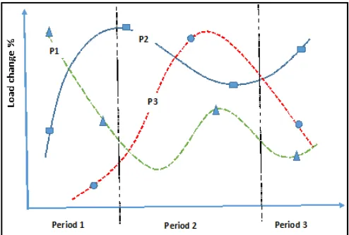
There are different polynomials defining the target load demands over time period. These polynomials can be of different orders depending on the number of measuring points in any one period of time, as depicted in the following figure
Fig.2: Target load polynomials
Figure 2 exhibits a case study in which three time periods are considered for the three target zones load demands, whereas each target requires a different load demand, as shown. A maximum 100% load is the default WSN design reference, so that energy can be preserved when the target load is below this reference, and might reach infinity when there was no demand, i.e. energy is saved for future demand. Note that any number of measuring points per period can be taken in principle, but we shall consider one measuring point per period here. The polynomial orders can be of any size for the different targets.
II. POWER/LIFETIME FORMULATION
The above sensor-target network, depicts sensor collection S and target zones T, with a number of subsets of sensor covers C with time weights tw1, tw2 ..twk [0,1] and sensor cover failure probabilities cp1, ..cpk,, as shown in Fig. 3, where k is the maximum number of sensor covers we can find. It can be seen that for this example, there exist 4 such sensor subsets.
Fig.3: Sensor failure probabilities
The probability that a sensor cover Cr={s1, s2, ..sl}, l ϵ[1,n];
r ϵ [1,k], fails to cover all the target set T={t1, t2,..tm} is
Cfpr=1-∏ (1-tfpj) (1)
tfpj=∏ sfpij (2)
where tfp is the target failure probability of j targets by r sensors subsets ( r ϵ [1, k] ), thus
Cfpr=1- ∏j=1 m [1- ∏i=1 l (sfpij)] (3) where sfpij is the failure probability of sensor i to target j, and Cfpr is coverage failure probability of a subset or group
of sensors covering all targeted zones, which is assumed to be less than α; a predefined maximum failure probability
tfp, which is target failure probability of one targeted zone
by all sensors. It is required to find these k sensors subsets activation in order to maximize the network lifetime as
T=max ∑ tk wk (4)
Where tk and wk are the lifetime of each sensor subset and its effecting weight, with the assumption that lifetime of each sensor is normalized to a value of 1. The aim is to increase this lifetime not on the expense of reducing the coverage.
It is assumed that the transmitted and received power are related according to the following free space model
Pr(d)=Pt Gr Gtλ2 / {(4π)2 d2 L} (5)
And for the non-free space
Pr(d)=Pt Gr Gt hr2 ht2/ d4 (6)
Where Gr and Gt are equal to 4π Ae /λ2 for receiver and transmitter, Ae is the effective antenna distance aperture, λ is wavelength, L is a lost factor, d is covered distance and Pt is transmitted power. And hr and ht are receiver and transmitter heights. It can be deduced that sensor power and energy are linearly proportional with the switching target load in demand, and thus on sensors energy.
Fig.4: Order of polynomial degree order with 4 measuring
Infogain Publication (Infogainpublication.com) ISSN: 2454-1311
www.ijaems.com Page | 819 The target load demand polynomial degree r can be of any
order depending on measuring points p , in which n<p. Figure 4 shows that different polynomial degree 0th, 1st, 2nd, 3rd can be generated from the shown 4 measuring points.
Three considerations are taken into account for the above algorithm:
1- The required overall network failure coverage probability α is adjusted as
αnew= αold + (1- max(Li(j))) (7)
Where Li(j) is for all ith targets in the jth interval t. If this value exceeds unity, then it is equated to 1. This would increase the number of possible sensor subsets and therefore a possible lifetime increase.
2-The individual target failure probabilities of the j targets are increased by their load demands Li(j) as specified in time period intervals as
tfpi, new= tfpi, old +(1-Li) (8)
Again, if this value exceeds unity, then it is equated to 1. 3-The total subset lifetime Ttotl is calculated as
Ttotal= ∑ Tj (9)
In which Tj is lifetime preserved or saved for period interval j, which is evaluated as:
Tj= i Tj / ∑ Li (10)
i.e. individual period lifetime is increased by i/∑ Li due to the fact that maximum default or reference energy is equal to the number of target time zones i/t(j)
The total lifetime is computed by adding all lifetimes of the switching load periods, according to the area under the load demands, as depicted in equations 9-10.
III. PROGRAM ALGORITHM PSEUDOCODE
The main procedure of program is finding subsets of N sensors that can cover M target zones within specific required coverage failure probability α, and for each time interval of target load demands. There can be maximum k
=2N subsets, in order to fulfill the condition of achieving α, or less. It is required to investigate among all these subsets, the possible shared subsets j, whose sensors are not shared; thus enabling each subset to operate alone and independently.
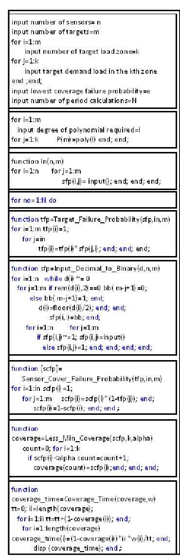
The program algorithm pseudocode (Fig. 5) depicts procedures and functions of the simulation program implemented on a Matlab platform. This algorithm is to compute WSN sensors energy for any load demand of target coverage, by finding all possible subsets of sensors that
achieve overall required coverage over several time periods of target load demands. It is noted, that if one sensor is shared in more than one subset, then the total activation time of that sensor cannot exceed its normalized lifetime.
Fig.5: Program pseudocode of energy-lifetime algorithm
Infogain Publication (Infogainpublication.com) ISSN: 2454-1311
www.ijaems.com Page | 820
failure probabilities for a number of sensors to any target. Then the coverage of the k sensors subsets to the M targets, as scfpr=1-∏(1-tfpj), in which r ϵ [1, k], is calculated, i.e.
SSS={{SS1}, {SS2}……..{SSr}};
Where r ϵ [1, k], in which SS={S1, S2,……….Sk}.
There are maximum 2k subsets of SSr, in which some utilize one or more same sensors in Sk. The procedure is repeated for each identified time period, according to the target load demands which are inputted. Total lifetime - energy is summed up for all periods with reference to the total area under the load demand intervals.
At each period, several measuring load demands are taken for each time period and for each target. A polynomial of required degree is formed for each target load pattern. The algorithm differentiates between different cases such as on-off load pattern, similar load distributions for all time periods, variable load distributions for the targets in each time interval, or a combination of all these cases.
IV. MATLAB SIMULATION OF CASES
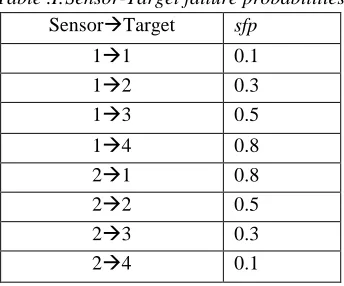
Throughout the different cases studied here, a minimum coverage failure probability of 0.1 is selected, which maintains at least 90% of required sensors-targets coverage. Two sensors are selected to cover 4 targets with the following sensor failure probabilities sfp, which are of a random nature, as depicted in Table I.
Table .I:Sensor-Target failure probabilities
Sensor Target sfp
1 1 0.1
1 2 0.3
1 3 0.5
1 4 0.8
2 1 0.8
2 2 0.5
2 3 0.3
2 4 0.1
The algorithm is tested on a general case study with target load demands, each having a polynomial of different degree, i.e. 1,2,3 and 4 degree. Up to 5 measuring load points are taken depending on polynomials. Also, 10 switching intervals are chosen, for the sensors over the period. The network lifetime is increased to 2.8574 times the lifetime when no switching is imposed. This is shown in Fig. 6
Fig.6: The general case study
It can be seen that at the end of each switching interval, a certain amount of lifetime, and consequently sensors energy and power, has been increased.
Then the following cases are studied, in which each of the four targets are having the following different load demand polynomials:
(1) Constant polynomial for all targets, in which each of the targets is having a constant load demand, as depicted in Table II. The lifetime is increased by 2.5 P.U.
Table.II: Constant load demand
T Time (P.U.) Load (P.U.) Polynomial/d egree 1 2 3 1 2 3
1 0.1 0.5 0.9 0.5 0.5 0.5 P=0.5 /0 2 0.1 0.5 0.9 0.2 0.2 0.2 P=0.2 /0 3 0.1 0.5 0.9 0.8 0.8 0.8 P=0.8 /0 4 0.1 0.5 0.9 0.4 0.4 0.4 P=0.4 /0
(2) Linear polynomial for all targets, in which each of the targets is having a different linear load relation with time, as depicted in table III. The lifetime is increased by 2.25 P.U.
Table.III: Linear load demand
T Time (P.U.) Load (P.U.) Polynomial/degree 1 2 3 1 2 3
1 0.1 0.5 0.9 0.1 0.5 0.9 P=X /1 2 0.1 0.5 0.9 0.9 0.5 0.1 P=-X +1 /1 3 0.1 0.5 0.9 0.5 0.3 0.1 P=-0.5X +0.55 /1 4 0.1 0.5 0.9 0.1 0.3 0.5 P=0.5X + 0.05 /1
(3) Parabolic polynomial for all targets, in which each of the targets is having a different parabolic load
1 2 3 4 5 6 7 8 9 10 0
0.5 1 1.5 2 2.5 3
Infogain Publication (Infogainpublication.com) ISSN: 2454-1311
www.ijaems.com Page | 821 relation with time, as depicted in table IV. The
lifetime is increased by 3.25 P.U.
Table.IV: Parabolic load demand (degree 2)
T Time (P.U.) Load (P.U.) Polynomial/degree 1 2 3 1 2 3
1 0.1 0.5 0.9 0.2 0.6 0.4 P=-1.8750X2 + 2.1250X+0.0062 /2 2 0.1 0.5 0.9 0.9 0.4 0.7 P=2.5 X2 -2.75X +
1.1500 /2 3 0.1 0.5 0.9 0.4 0.6 0.5 P=-0.9375X2 +
1.0625X+0.3031 /2 4 0.1 0.5 0.9 0.8 0.4 0.6 P=1.875X2
-2.125X + 0.9938 /2
(4) Then this parabolic load demand nature (case 3) is approximated with both a linear polynomial relationship of degree 1, and a constant polynomial relationship of degree 0, in which the network lifetimes are increased by 3.6 and 3.35 respectively. It can be noted that this polynomial degree fitness correlation depends on the load nature. This is depicted in Table V.
Table.V: Parabolic load demand (degree 1 and 0)
Degree 1
T Time (P.U.) Load (P.U.) Polynomial/degree 1 2 3 1 2 3
1 0.1 0.5 0.9 0.2 0.6 0.4 P=0.25X+0.275 /1 2 0.1 0.5 0.9 0.9 0.4 0.7 P=-0.25X+0.791 /1 3 0.1 0.5 0.9 0.4 0.6 0.5 P=0.125X+0.437 /1 4 0.1 0.5 0.9 0.8 0.4 0.6 P=-0.25X+0.725 /1 Degree 0
T Time (P.U.) Load (P.U.) Polynomial/degree 1 2 3 1 2 3
1 0.1 0.5 0.9 0.2 0.6 0.4 P=0.4X /0
2 0.1 0.5 0.9 0.9 0.4 0.7 P=0.6667X /0 3 0.1 0.5 0.9 0.4 0.6 0.5 P=0.5X /0
4 0.1 0.5 0.9 0.8 0.4 0.6 P=0.6X /0
(5) Varying number of switching points, in which the parabolic load demand polynomial of the above case study (case 3), is varied with different switching intervals. It can be also noted that the correlation depends on the target load pattern nature. This is depicted in Table VI
Table.VI: Variable switching periods
Number of
switching Lifetime
2 2.8
5 3.25
10 3.35
(6) Varying polynomial for same target load measuring points, in which the load demand of case 3 is formulated as degree 2, 1 and 0. The lifetime is increased to approximately 3.5 depending on the individual target load profile. This is depicted in Fig. 7
Fig.7: Lifetime versus load polynomial degree
V. CONCLUSION
A lifetime-energy control algorithm of an ad hoc network has been successfully implemented and simulated on the Matlab platform, in which a wireless sensor network (WSN) comprising of two sensors and 4 targets is analyzed. A number of different cases of target load profiles, as well as the number of switching of sensors subsets, are considered. A case study; in which a minimum coverage failure probability of 0.1 is studied with sensor failure probabilities of random nature, ranging from 0.1 to 0.9. Target load demand profiles are assumed with different polynomial degrees ranging from 0 to 4. The network lifetime is increased to 2.8574 times the lifetime when no switching is imposed.
The control algorithm reads 3 values or measuring points of each target load demand over a per unit period of time. This is fixed for all scenarios studied. As load demand is reduced from rated levels, the network lifetime is increased from 2.25 to 3.6 P.U. depending on the nature of load polynomials. It is deduced that this increase depends on the individual load profile nature, and doesn't follow a certain
0 0.5 1 1.5 2 2.5 3 3.5 4 1
1.5 2 2.5 3 3.5 4
Polynomial Degree
L
i
f
e
t
i
m
e
Target Lifetime of different polynomial degrees
1
Infogain Publication (Infogainpublication.com) ISSN: 2454-1311
www.ijaems.com Page | 822
profile. Six different scenarios are studied: 1. Constant load profiles for all targets 2. Linearly varying profiles for all targets 3. Parabolic varying profiles for all targets
4. Polynomial degrees of degree 0 to 2 fitting the same load values
5. Variable switching periods from 2 to 10
6. Formulating parabolic varying load into polynomials of degree 0 to 2
There was no correlation among these different scenarios, although the lifetime is increased up to 3.6 P.U.
Execution time required for solving these scenarios increases largely, depending only on the number of sensor subsets, i.e. 2r, r ≤ k=2N, which corrupts the program and
terminates with an error, but as long as both N and r, are within reasonable values, then the algorithm executes successfully even with so many time periods of load intervals.
REFERENCES
[1] I.F. Akyildiz, et.al., “A Survey on sensor networks”, Communication Magazine, IEEE, 40(8), pp. 102-114, 2002
[2] Y.C. Wang, et. Al., “Efficient placement and dispatch of sensors in a wireless sensor network”, IEEE Transactions on Mobile Computing, 7(2), pp. 262-274, 2008.
[3] C.F. Huang, et.al., “The coverage problem in a wireless sensor network, Mobile Networks and Applications”, 10(4), pp. 519-528, 2005.
[4] T. Yan, et.al., “Differentiated Surveillance for sensor networks, Proceedings of the 1st International Conference on Embedded Networked Sensor Systems”, pp. 51-62, ACM, 2003.
[5] M. Cardei, et.al., “Energy-efficient target coverage in wireless sensor networks”, IEEE 24th Annual Joint Conference of the IEEE Computer and Communications Societies Proceedings, Volume 3, pp. 1976-1984, 2005.
[6] S. Kumar, et.al., “Barrier coverage with wireless sensors”, Proceedings of the 11th Annual International Conference on Mobile Computing and Networking, pp. 284-298, ACM, 2005
[7] C. Gui, et.al., “Virtual patrol: a new power conservation design for surveillance using sensor networks”, IEEE Proceedings of the 4th International Symposium on Information Processing in Sensor Networks, pp. 33, 2005.
[8] K.P. Shih, et.al., “On connected target coverage for wireless heterogeneous sensor networks with multiple sensing units”, Sensors 9(7), pp. 5173-5200, 2009. [9] S.Y. Wang, et.al., “Preserving target area coverage in
wireless sensor networks by using computational
geometry”, IEEE Wireless Communications and Networking Conference (WCNC), 2010 IEEE, pp. 1-6, 2010.
[10] K.P. Shih, et.al., “A distributed active sensor selection scheme for wireless networks”, IEEE Computers and Communications, Proceedings of the 11th IEEE Symposium, pp. 923-928, 2006.
[11] J. Chen, et.al., “Modeling and extending lifetime of wireless sensor networks using genetic algorithm”, Proceedings of the First ACM/SIGEVO Summit on Genetic and Evolutionary Computations, pp. 47-54, ACM, 2009.
[12] H. Zhang, et.al., “A distributed optimum algorithm target coverage in wireless sensor networks”, IEEE Asia-Pacific Conference on Information Proceedings, Volume 2, pp. 144-147, 2009.
[13] H. Zhang, “Energy-balance heuristic distributed algorithm for target coverage in wireless sensor networks with adjustable sensing ranges”, IEEE Asia-Pacific Conference on Information Proceedings, Volume 2, pp. 452-455, 2009.
[14] A. Dhawan, et.al., “A distributed algorithm framework for coverage problems in wireless sensor networks”, International Journal of Parallel, Emergent and Distributed Systems, 24(4), pp. 331-348, 2009. [15] J. Wang, et.al., “Priority-based target coverage in
directional sensor networks using genetic algorithm”, Computers & Mathematics with Applications, 57(11), pp. 1915-1922, 2009.
[16] Z. Hongwu, et.al., “A heuristic greedy optimum algorithm for target coverage in wireless sensor networks”, IEEE Pacific-Asia Conference on Circuits, Communication and Systems, pp. 39-42, 2009. [17] A. Majid, “Matlab Simulations of Ad Hoc Sensors
Network Algorithm”, International Journal on Recent and Innovation Trends in Computing and Communication, Volume 3, Issue 1, January 2015. [18] A. Majid, “Algorithms With Simulations of Network
Sensors Lifetime and Target Zones Coverage”, International Knowledge Press, IKP Vol. 6, Issue 3, Journal of Mathematics and Computer Research ISSN No 2395-4205 Print, 2395-4213 On line, June 2015 [19] A. Majid, “Maximizing Ad Hoc Network Lifetime
Using Coverage Perturbation Relaxation Algorithm”, WARSE International Journal of Wireless Communication and Network Technology Vol. 4, No 6, Oct-Nov 2015, ISSN 2319-6629