© 2016 IJSRSET | Volume 2 | Issue 2 | Print ISSN : 2395-1990 | Online ISSN : 2394-4099 Themed Section: Engineering and Technology
Implementation of Biometric Voting Machine Using Aadhar Card
Gowri, Guruprasanth, Jaya Surya. D, Krishnan. S, Dhanasekaran. S
Department of Electrical Communication Engineering,Sri Eshwar College of Engineering, Chennai, Tamilnadu, India
ABSTRACT
Today we all know that bogus (fake) voting is still major drawback in the elections. We can transform from ballot paper to electronics voting machine (EVM), but this problem cannot avoid completely. This paper attempt to solve this problem. Today we all have AADHAR CARD so the Government has all the data base of us including finger print and retina. As we all know that general election happened last year but no one really talks about the use of AADHAR CARD. So if we used that database effectively with the help of micro controller then we can completely overcome the problem of bogus voting. This paper shows how this problem can be solved with the help of combination of biometric finger print scanner and micro controller.
Keywords : PIC Microcontroller, Fingerprint scanner, EVM, LCD Display, AADHAR CARD, Keypad
I.
INTRODUCTION
This paper examines policy regarding the electronic approaches and developments towards avoidance of bogus voting and secured voting system. Finger print scanner is used for identity of voter and discussed other parameter which is implemented in this paper.
The user has to show his voter ID card whenever he goes to the polling booth to give vote. This is a time consuming process as the person has to check the voter ID card with the list he has, confirm it as an authorized card and then allow the person to poll his vote but this technique not give security of right candidate voting. Thus, to avoid this kind of problems, we have designed a finger print based bogus avoidance of voting system where the person not required carries his ID and also avoid the bogus voting based on database of AADHAR CARD.
Today we all users have AADHAR CARD. First initially the database of finger prints which based on AADHAR CARD stored into the finger print scanner. When user put his/her fingerprint on figure print scanner, scanner checks it with previously stored in database. If finger print matched then EVM is enabling and the user is allowed to gives his/her vote. If that user
comes again to give vote, a siren will blow that indicate the bogus voting. So we can easily prevent this kind of problems. For developing this kind of system we used PIC microcontroller. PIC is heart of entire system.
II.
METHODS AND MATERIAL
1. Existing System
On a particular election day, the election booths become heavily crowded. People have to stand in the scorching sunlight for hours just to cast “a vote”. Aged people and senior citizens have to face the same problems. Pregnant women and women with kids face great difficulty for the lack of various facilities; as a result a great percentage of these women do not come to the booths to cast their votes.
2. Problems With Existing System
Do not guarantee transparency: A voter could not check what happened to his/her vote i.e., whether it has been properly recorded in the system database or not.
Since the EVMs move through different hands therefore they are susceptible to manipulations by fraudulent.
Inefficient process of identity checking: Here valid voters are just checked by polling officers by their photos on the voter card therefore more or less similar looking persons can give the vote on behalf of another.
Since the structure and composition of the EVM is very simple so substituting a Look-Alike fake EVM with the real one can be done easily.
Susceptible to manipulations: by attaching additional hardware to the control unit’s circuit board, an attacker could directly read and write the EEPROM chips that record the votes.
Natural Hazards: high temperature, humidity and adverse climatic conditions can damage the EVM chips and internal circuitry. Moreover attack by vermin, rats, fungus or mechanical danger can generate malfunctions.
Small chips attached to the EVMs that can be controlled by fraudulent through radio waves or infrared can alter or manipulate the functioning of the machine leading to alter the vote results-research proved by Hari Prasad, Rop Gonggrijp, and J. Alex Halderman in “Security Analysis of India’s Electronic Voting Machines”.
3. Proposed System
A. Working Procedure of the proposed system
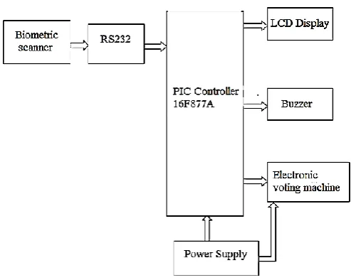
Figure 1. Block diagram of the proposed system
This work is basically an embedded system that makes the things easy avoidance of bogus voting during the time of elections. The user, who wants to poll his vote, has to punching the finger in finger print scanner at the counter at the polling booth. Based on finger print identify the identity of user. We know that user’s finger print based on AADHAR CARD already saved in database of system.
The working of system explained in two modes: 1. Enrolling mode
2. Punching and identification mode
When power on, whole system is active. Micro controller ready to gate signal from fingerprint sensor.
Enrolling Mode:
This mode is hidden part of system. By using Enrolling mode we store the few collection of finger print. In this mode we enroll the finger print of user by sending appropriate command. When user put the finger print on finger print scanner, generate the Image file of finger. Again put the finger print on finger print scanner for confirmation of valid finger print. Then generate another Image file. After completion of this step generate unique number of template file by combination of both Image file. This unique number store in the EEPROM of finger print scanner.
After enrolling all finger print successfully, the system is ready for vote cast. Now user punches his/her finger on fingerprint scanner. During this mode the fingerprint of the user is compared with the finger prints already enrolled in the memory by algorithm which is embed in micro controller. If it is matched a message “IDENTIFICATION CONFIRM” will be displayed on LCD. If not then buzzer beeps three times which indicate the bogus user of voting. After confirmation of user, he/she permit to voting. Once the user presses the button corresponding to the candidate of her/his choice, digital number is generated and sent to the control unit. Once the voting is over message “THANK YOU FOR VOTING” is displayed on LCD and buzzer beeps one time. “SORRY CANT ACCESS” message will be displayed if the same user tries to vote again. The system returns to the identifying mode and starts all over again for next voting.
B. Description of the Proposed Algorithm
Step1: ON Power supply
Step2: Active all devices
Step3: Enroll the fingerprint of users which is given in
AADHAR CARD
Step4: user puts his/her fingerprint
Step5: if finger print not matched go to step11
Step6: if matched then allowed to voting
Step7: Enter voting zone
Step8: choose your candidate
Step9: voting completed then buzzer beeps single time
Step10: go to Step4
Step11: buzzer beep three time which indication of
unauthorized user
Step12: go to Step4
C. Architecture of the proposed system
The main components of the voting system is listed as follows.
1) PIC Microcontroller
2) Fingerprint Identification Module
3) LCD
4) Power Supply
1) PIC Microcontroller - The PIC (founded by Microchip) 16F877A is an CMOS-FLASH based high-performance 8-bit RISC Microcontroller. This powerful (200 nanosecond instruction execution) yet easy-to-program (only 35 single word instructions) microcontroller packs Microchip's powerful PIC® architecture into an 40 pin package . The PIC16F877A features 256 bytes of EEPROM data memory, self programming, an ICD, 2 Comparators, 8 channels of 10-bit Analog-to-Digital (A/D) converter, 2 capture/compare/PWM functions, the synchronous serial port can be configured as either 3-wire Serial Peripheral Interface (SPI™) or the 2-wire Inter-Integrated Circuit (I²C™) bus and a Universal Asynchronous Receiver Transmitter (USART). All of these features make it ideal for more advanced level A/D applications in automotive, industrial, appliances and consumer applications.
Figure 3. Pin Diagram
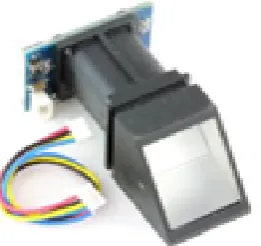
Figure 3. R305 Module
Description
Power DC 4.5V-6.0V
Interface UART (TTL logical level)/ USB 1.1 Working current Typical: 100mA ,Peak: 150mA Matching Mode 1:1 and 1:N
Image acquiring time <0.5s Template size 512 bytes FAR <0.001%
FRR <0.1%
Average searching time < 0.8s (1:880) Window dimension 18mm*22mm
3) LCD
A liquid crystal display (LCD) is a flat panel display, electronic visual display, or video display that uses the light modulating properties of liquid crystals (LCs). LCs do not emit light directly. They are used in a wide range of applications, including computer monitors, television, instrument panels, aircraft cockpit displays, signage, etc. They are common in consumer devices such as video players, gaming devices, clocks, watches, calculators, and telephones. LCDs have replaced cathode ray tube (CRT) displays in most applications. They are available in a wider range of screen sizes than CRT and plasma displays, and since they do not use phosphors, they cannot suffer image burn-in. LCDs are, however, susceptible\to image persistence. LCDs are more energy efficient and offer safer disposal than CRTs. Its low electrical power consumption enables it to be used in battery-powered electronic equipment. It is an electronically modulated optical device made up of any number of segments filled with liquid crystals and arrayed in front of a light source (backlight) or reflector to produce images in color or monochrome. The most flexible ones use an array of small pixels. The earliest
discovery leading to the development of LCD technology, the discovery of liquid crystals, dates from 1888. By 2008, worldwide sales of televisions with LCD screens had surpassed the sale of CRT units. LCDs available in two models: Character LCD and Graphics LCD. The character LCD displays ASCII values and graphics LCD displays graphics. Character LCDs are available in various kinds of models.
Figure 4. LCD Pinout (16*2)
No. Of characters Lines: 8-1, 16-1, 16-2, 16-4, 20-4, 40-4,…
Dots - Dots: 122-32, 128-64, 240-128, 320-240,…. Colour: Yellow, Green, Gray, Blue….
Graphics LCDs are also available with different sizes and colors.
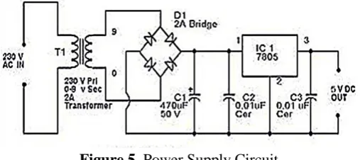
4) Power Supply
Power supply unit consists of the following units: 1. Step down transformer
2. Rectifier unit 3. Input filter 4. Regulator unit 5. Output filter
RECTIFIER UNIT: We have to convert AC voltage to DC using rectifier. Bridge rectifier is used. This o/p voltage often rectifier is in rippled form, so we have to remove ripples from DC voltage.
INPUT FILTER: Capacitor acts as filter. The principle of the capacitor is charging and discharging. It charges in the positive half cycle of the AC voltage and it will discharge in the negative half cycle. So this allows only AC voltage and does not allow the DC voltage. This filter is fixed before the regulator.
REGULATOR UNIT: Regulator regulates the o/p voltage constant depends on upon the regulator. It is classified as follows.
1. Positive regulator 1. Input pin 2. Ground pin 3. Output pin
It regulates the positive voltage 2. Negative regulator
1. Ground pin 2. Input pin 3. Output pin
It regulate the negative voltage
OUTPUT FILTER: Capacitor acts as filter. The principle of the capacitor is charging and discharging. It charges in positive half cycle of the AC voltage an it will discharge in negative half cycle. So it allow only allows AC voltage and does not allow the DC voltage. This filterer fixed after the regulator.
Figure 5. Power Supply Circuit
III.
RESULT ANALYSIS
The final experimental result in which person is giving his or her vote using biometric system and that templates match with the previously stored templates and the person can vote. And second time that person trying to give vote with the wrong fingerprint that indicates the
fake voting and the alarm sound will blow. So this way we can completely overcome the problem of bogus voting.
IV.
ADVANTAGES
1. The system is highly reliable, tamper-proof and secure.
2. In the long run the maintenance cost is very less when compared to the present systems.
3. Illegal practices like rigging in elections can be checked for.
4. It is possible to get instantaneous results and with high accuracy.
5. This unique fingerprint voter ID card can be used for identification purpose in Govt./Semi-Govt. bodies. E.g.: When applying Passport, Driving license, etc.
V.
FUTURE SCOPE
1. This system can be implemented in a few years, with recent development in technology, a fingerprint scanner is neither too expensive nor too complicated to use on daily basis.
2. Memory of finger print module can be expanded. We can use a 1mb flash memory finger print module for increasing the capacity.
3. External memory can be provided for storing the finger print image, which can be later accessed for comparison.
4. Audio output can be introduced to make it user friendly for illiterate voters.
VI.
CONCLUSION
also in other countries the face of the election procedure can be changed drastically using this technology.
VII.
REFERENCES
[1] Firas I. Hazzaa, Seifedine Kadry, Oussama Kassem
Zein, 'Web-Based Voting System Using Fingerprint: Design and Implementation’, International Journal
of Computer Applications in Engineering
Sciences,VOL II, ISSUE IV, DECEMBER 2012
[2] Mayuri U. Chavan, Priyanka V. Chavan,Supriya S.
Bankar, 'Online Voting System Powered by
Biometric Security using Cryptography and
Stegnography’, International Journal of Advance Research in Computer Science and Management Studies, Volume 1, Issue 7, December 2013
[3] Schurmann, C.; IT Univ. of Copenhagen,
Copenhagen, Denmark. Electronic Elections: Trust Through Engineering‖, First international workshop Requirements Engineering for e-Voting Systems (RE-VOTE), 2009.
[4] Lin Hong. "Automatic Personal Identification Using
Fingerprints", Ph.D. Thesis, 1998.
[5] D. Maltoni, D. Maio, A. K. Jain, and S. Prabhakar,
Handbook of Fingerprint Recognition. New York: Springer-Verlag, 2003.
[6] Anil K. Jain and David maltoni. , Handbook of
Fingerprint Recognition, Springer-verlag New York, Inc., Secaucus, NJ, USA, 2003.
[7] Tadayoshikohno_ Adamstubblefield Avield
Rubidans.Wallach Analysis of an Electronic Voting system‖, IEEE symposium on Security and Privacy 2004.
[8] Y. A. Zuev and S. Ivanon, The voting as a way to