A Proposal for a Multi-Agent based Synchronization
Method for Distributed Generators in Micro-Grid
Systems
Paolo Giammatteo
1,∗, Concettina Buccella
1, Carlo Cecati
11Department of Information Engineering, Computer Science and Mathematics, University of L’Aquila, Via Vetoio,
67100, L’Aquila, Italy
Abstract
A synchronization technique based on the Multi-Agent Systems approach, is proposed for a group of Distributed Generators belonging to a Micro-Grid. The Average Time Synchronization consensus algorithm is used. A detailed description of system’s hardware architecture is given and several simulations of the dynamic are performed. Since the synchronization take place on a dedicated layer, different from the power grid one, the proposed technique does not require voltage and current measurements. This gives scalable, flexible and resilient characteristics to the system by construction.
Keywords: ConsensusAlgorithm,Distributed PowerGeneration, Electric Grid, Multi-Agent System, Power Systems,Synchronization
Received on 6 December, 2015; accepted on 30 December, 2015; published on 21 April, 2016
Copyright © 2016 Paolo Giammatteo et al., licensed to EAI. This is an open access article distributed under the terms of the Creative Commons Attribution licence (http://creativecommons.org/licenses/by/3.0/), which permits unlimited use, distribution and reproduction in any medium so long as the original work is properly cited.
doi: 10.4108/eai.21-4-2016.151160
1. Introduction
Until the advent of distributed generation, electric power grids were conceived as hierarchical systems, with few large electrical power plants (hundreds MVA), the large majority of which are electro-mechanical generators driven by heat-engines fueled by chemical combustion or nuclear fission, transmission and distribution lines and, at bottom level, a huge number of passive loads [1]. With such a philosophy, the energy flow is unidirectional, the control of the whole grid is centralized and the whole system including power plants, transmission lines, substations and distribution lines is coordinated by a Supervisory Control and Data Acquisition (SCADA) system [2, 3]. The potential difficulties and the limits imposed by such configuration, could lead to face catastrophic situations in case of large scale power blackouts [4,5].
Distributed generation is based on a different approach: a huge amount of power plants, ranging from few kW up to MW and scattered on the territory, are directly connected with distribution lines, thus producing energy close to customers. In some circumstances, customers themselves produce energy, which is injected in the grid and sold to other customers
∗
Corresponding author. Email:[email protected]
through Distribution System Operators (DSO) [6, 7]. The high number and the different power level of Distributed Generators (DGs), lead to face several power grid interface problems. The huge number and the different power level of the available generators and energy fluctuations caused by, for example, intrinsic nature of renewable energy sources, lead to face several power grid interface problems. Voltage and currents produced by power plants must primarily satisfy strict requirements in terms of amplitude, frequency, phase and quality of waveform, which is expected to be pure sinusoidal. Total Harmonic Distortion (THD) and more in general Power Quality (PQ) requirements must be strictly ensured. This result can only be achieved using power converters, i.e. electronic interfaces inserted between distributed generators and power grid with the purpose of making the produced energy as much as possible similar to the one already available in the grid [8].
However, power electronics alone is not sufficient for full and efficient integration of DGs within the grid and a complex Information and Communication Technology (ICT) infrastructure is required, leading to the concept of Smart Grid (SG) [9]. In SGs, the power grid layer necessary to sustain energy flows, is now parallelized with an information and communication layer, necessary for exchanging real time processing
on
Industrial Networks and Intelligent Systems
data among generators, distribution chain nodes and customers [10,11]. A decentralized architecture can be then obtained consisting of a number of interconnected Micro-Grids (MGs) [12, 13], including generators, loads and storage systems (SSs). Power and real-time informations flow across two separate layers in both ahead and astern, without any fixed direction. The resulting two networks (power grid and information network) could be distinct from a virtual level point of view, but they may insist either on the same physical infrastructure, as in the case of Power Line Communications (PLCs) [14], or on two different and
dedicated physical media.
Many contributions to the decentralization of the power grid and its control, were presented, and different software architectures and paradigms were proposed, in order to define specific standards for the SG, necessary for avoiding proliferation of abnormal situations too difficult to be managed. The Multi-Agent Systems (MASs) approach, already exploited in industrial and scientific domain, is an example of these paradigms. An agent is an autonomous entity which observes through sensors and acts upon an environment using actuators and a MAS is a system composed of multiple interacting intelligent agents within an environment [15]. The MAS potential for the power grid is well documented in several simulation studies and projects [16, 17] and papers [18] and [19] give specifically a vision of how the MASs approach could be used into the power grid. The main benefit of this approach is that the SG can be seen as a very complex system, consisting of many distinct nodes (generators, loads, transformers, etc...) interconnected among each other, with different tasks to be accomplished [20]. MASs approach enhance and fits several functionalities typical of SG, such as distributed and real-time control, diagnosis, negotiation/consensus and self-maintenance. Furthermore, is surely useful for the large-scale integration and coordination of DGs and SSs.
Within the most important MAS applications, it is possible to find the control strategies for parameters optimization such as voltage level [18, 21] and the field of intelligent grid operations such as grid restoration and power distribution management [22,
23]. As mentioned above, the quality of power signals is fundamental for the functionality of a group of DGs inside a MG. While for the signal amplitude and THD, the generator’s converter is capable to control and regulate them according to power grid specifications, injection of the generator signal or better signal synchronization inside the grid, depends on the presence of the other generators. Traditional synchronization methods used for large power plants appear too expensive and complex to be used in distributed generation. MASs paradigm, with the use of
a consensus algorithm [24], could be a viable alternative not only to these approaches, but also to the classical and known techniques of power grid synchronization for DGs.
This paper intends to focus its attention on the topic of the synchronization of a group of DGs inside a MG, by using the MAS approach. The paper is organized as follows. In Section 2 a review of synchronization techniques for distributed systems is given. In Section
3 definitions and mathematical model are described. In Section4 the implementation of system’s hardware architecture and simulations are discussed. Finally, Section5presents the conclusions of the paper.
2. Synchronization methods for distributed systems
The aim of this Section is to review the most important synchronization techniques and protocols already used in the electric system and more in general for distributed systems.
2.1. Synchronization methods used for distributed
generators in power grids
There are two main categories of methods used for the synchronization of DGs. They are respectively the open-loop and the closed-open-loop methods [25].
Open-loop methods. Among the open-loop methods there are the Zero-Crossing (ZC) and the Filtering of the Grid Voltage (FGV). The ZC method is the most simple methodology to detect the phase information of a sinusoidal signal [26] and is also used for AC-DC converters with triacs or thyristors to calculate the firing angle for distributed gating pulses [27]. The phase is calculated through the use of a timer, which is always restarted when the input signal crosses the zero value. This specific method is very vulnerable when large loads are switched on, because harmonics can arise, providing an input signal no longer perfectly sinusoidal, but soiled by other frequencies, usually very high respect to the fundamental, and so causing multiple zero-crossing at high frequency, making the method totally unreliable.
matrix with a feedback mechanism with the help of the power grid measured quantities. The use of the EKF as a power grid synchronization method is not so diffused. Anyway, its use as a synchronization method to the power grid is technically feasible, but it requires a high computational resources, when implemented on a Digital Signal Processor (DSP).
Unfortunately, also these two methods are considered high sensitivity to the frequency deviations, voltage distortions and imbalance [26]. Infact, for example, SVF methods are not satisfactory in providing the desired performance and many difficulty and limitations are found in presence of noise and harmonics. So sensitivity to the input frequency variations and imbalance are the most important problems identified.
Closed-loop methods. Differently from the previous
case, closed-loop methods insert in the process of synchronization, the acquisition of useful informations related to the grid to which the DGs want to synchronize. Infact, due to these acquired informations, such as the voltage and current values, a feedback loop triggers for the calculation of the necessary parameters. This loop helps the synchronization method to be more accurate, precise and, most important, reliable respect to the open one, giving the right parameter values in order to have a synchronized generator with the power grid. They are much more diffused than the open loop methods, thanks to their greater reliability, and so more attention is given to them.
A. Phased Locked Loop method. Typical examples of closed-loop methods include the PLL, which is a feedback frequency control system, whose functioning is based on the sensitive detection of phase difference between the input and output signals of a reference oscillator. In a nutshell, it consists of a system that allows to synthesize a signal, whose phase has a fixed relationship with that one of a reference signal. The PLL method is the most commonly used method of producing high frequency oscillations in nowadays communications instrumentation. The most, or maybe, the totality of the radio amateur or commercial receiver of any kind nowadays, employ at least one, if not several, PLL systems, to generate stable high frequency oscillations. The first PLL circuits were originally realized by Appleton in 1923 and Bellescize in 1932, and, as mentioned above, was mainly used for synchronous reception of radio signals [30]. Subsequently, PLL technique was used in various industrial fields such as communication systems. Infact, the first large-scale utilization of the PLL occurred in analog receivers for television devices, where a circuit with similar functionality was used for over three decades [30]. Then, other PLL applications were developed in the field of motor control systems [31] and in the induction heating power supplies
Phase Detector
Low-Pass Filter
Voltage Controlled
Oscillator
u(t) e(t) ef(t) y(t)
Figure 1. Basic topology of PLL.
[32]. However, the great popularity of this method started with the development of integrated circuits, which allow to realize, at low cost on a single integrated circuit, an entire PLL system. An example is the CD4046CMOS Micropower PLL, which became a popular integrated circuit. Many of the advanced technologies of recent years, including mobile phones, wireless communications, GPS and satellite and digital terrestrial television make an intensive use of the PLL circuit.
Recently, the PLL technique has been used for synchronization between grid-interfaced converters and the power grid, and nowadays covers the majority of the controllers of the grid-connected applications. In this case, the reference signal is the measured electric signal on the power grid to which the DG is connected. The PLL robustness and accuracy are basic to the operation of the controllers which are in charge to establish a synchronization with the power-grid. In general, the PLL classical configuration is shown in Figure (1). This mechanism can be implemented as either analog or digital circuits. Both implementations use the same basic structure. Both analog and digital PLL circuits include the four basic elements described in Figure (1), namely:
• Phase detector
• Loop filter
• Voltage-controlled oscillator
• Feedback path.
αβ/dq
Low-Pass Filter
Voltage Controlled
Oscillator
Vα Vq Vf ϑ
Vd
ϑ Quadrature
signal generation
Vβ
Figure 2. SRF-PLL for single-phase signals.
necessary to compensate this aspect [35], so a trade-off is necessary between the two characteristic of fast tracking as well as good filtering.
Other declinations of the PLL method exist, such as the Second Order Generalized Integrator PLL (SOGI PLL) and the Sinusoidal Tracking Algorithm (STA), also known as the Enhanced PLL (EPLL) [36], which gained a lot of importance in recent years. Good comparative analysis and results on different PLL techniques are reported in paper [25] for single-phase PV systems and in paper [37] for advanced inverters used to connect electric vehicles to the grid. Furthermore, it is worthy mentioning that there are several other sophisticated techniques like Decoupled Double Synchronously Rotating Reference Frame PLL (DDSRF PLL) [38], the Delayed Signal Cancellation PLL [39], the Fixed-Reference-Frame PLL (FRF PLL) [35] and the Dual SOGI PLL (DSOGI PLL) [40].
A new and recent PLL technique, which could be a suitable solution for the exploitation of interconnected renewable energy systems with a fault ride through capability, is presented in paper [41]. It consists in the hybridization of three PLL techniques, respectively the SRF PLL, the FRF PLL and the DDSRF PLL. The result of this hybrid operation is called the Decoupled Stationary Reference Frame PLL (DαβPLL). The advantages of this technique derive from the aforementioned PLL ones, operating accurately under balanced and unbalanced conditions and reducing the errors on the estimation of the phase angle and frequency, which is the main disadvantage of the DDSRF PLL. This leads to a faster time response, making the Dαβ PLL useful for interconnected renewable energy systems, with particular attention in the design of a fault ride through control. Improvements of the Dαβ PLL have been developed in papers [42,43], in particular its performances have been studied under grid faults, proposing an adaptive behavior.
However, all these method declinations show that the PLL is a control architecture which may be subject to the origin and/or to the propagation of interference and errors that normally travel through the reference signal of the grid, with consequent difficulties in the synchronization part of the generator. The Dαβ PLL
v=vm sin(ϑv) i
e=E sin(ϑ)
SSM Model XS
Figure 3. Model of an SSM connected to the grid.
method goes in this direction and propose a fast and accurate synchronization under harmonic distorted voltage and low-voltage grid faults. Anyway, the PLL technique always require the presence of a reference signal within the electrical power grid on which insists the generator that has to be synchronized.
B. The Sinusoid Locked Loop method. Another closed-loop technique, different from the conventional PLL synchronization methods discussed above, is presented in papers [44,45] and in book [46]. It is known as the Sinusoid Locked Loop (SLL) and it is based on the idea of mimicking a grid-connected synchronous machine, which does not exchange power with the grid. This because the generated signal is synthesized with the same instantaneous voltage as the grid voltage. So a generic distributed voltage source, which need to be synchronized to an existing power grid, which possess a prevalent signal, is seen as a Single-phase Synchronous Machine (SSM), with the aim that the active power P and the reactive powerQ, flowing out of this generator, have to be leaded to the zero value. Their formulas are shown as follows [45,46]:
P =vmE 2Xs
sin(θ−θv) (1)
Q= vm 2Xs [Ecos
(θ−θv)−vm] (2)
where all the parameters are defined in Figure (3). In order to fulfill the method, the values of Equations (1) and (2) must be equal to zero, and so that the conditions:
E=vm
θ=θv (3)
are verified. A frequency droop control is present in order to determine the correct phase which eliminate the active power flow, but the voltage droop control is not needed for the SLL because the generated voltage is expected to be the same as the voltagev, soE=vm.
occasionally voltage control) to allow parallel generator operation, so that loads are shared among generators themselves in proportion to their power rating [47]. As shown in [45,46], the SLL method is capable to provide fast times of response in synchronization, given that a small machine response (the DG) is surely faster than a big one response (the power grid).
2.2. Overview of the synchronization methodologies
in distributed systems
Distributed systems, in general, are defined as a set of spatially separated, independently running processes, each equipped with a local time clock. The synchronization of these processes is fundamental for the whole system of which they belong [48–50]. Distributed systems can be implemented in different manners. An example is a network consisting of spatially wide distributed computers, which have to be coordinated because they share and work on the same task. Another example is the interaction of different block functions on a chip. The power grid itself, consisting of many devices spread on a wide area and connected through an infrastructure, is a distributed system. So it is straightforward, that the capability to synchronize devices with high precision and align their local clocks is of primary relevance in several contexts [51, 52]. The alignment of device local clocks to a single system-wide time is generally achieved through the exchange of messages over the network according to a clock synchronization algorithm or protocol. The aim of this protocol is to keep the local time clock of a group of networked devices aligned to each other to the same system time. How the exact system time is provided to the running processes of any single device, competes to the operating system. All clock synchronization protocols work basically in the same way, and must pass necessarily at least through these following points, preferably in this order:
1. estimation of the local clocks deviations respect to the system time with the utilization of time-stamp messages
2. computation of the correct compensation values through the acquired measurements
3. correction of the local time clock for each node. These points could be slightly different or could be not so clearly separated in the process. The related operations, including the measurement of times and the exchange of informations, depends on a suitable choice of the time-stamp messages and the technique used to interchange these messages between the nodes of the network.
Mainly the estimation of the clock deviations are obtained through the time-stamps, taken by several
network nodes. In this case, it is really important the way how the time-stamps are produced and taken. The three most important methods are:
• Master-Slaves method: a special node (the master)
is in charge to keep the correct time and cyclically gives its time to the others (the slaves) who synchronize themselves to the value received
• Server-Clients method: a node (the server) is in
charge to keep the correct time and the others (the clients) ask explicitly for synchronization sending a message to the first one when they need
• Distributed method: each node sends
synchroniza-tion messages through the network, which are received by all the other reachable nodes, then a distributed procedure is taken, which enables them to reach a common average reference time value after some iterations of communication.
The clock compensation can be accomplished with two different steps:
1. clock rate correction: due to parameters like
tem-perature, or other intrinsic features, oscillators may suffer of rate deviations so they must be monitored and adjusted accordingly
2. clock offset correction: even in the case of ideal
clock with exactly the same frequency or rate, deviations may still occur on the offset value, because devices could be started at different time clock values.
Another aspect that must be considered is the transmission latency. The exchange of information among nodes is based on the communication services offered by the used network. Consequently, for every message exchanged, there is the propagation delay over the communication media (which depends on the physical distance between nodes and its material) and the pass-through delay of the network equipment, which is related to the used technology, the process running as well as the algorithms performed. For small networks, transmission latency of messages could be considered little and generally deterministic, while for large geographic networks, it could grow considerably and may suffer of stochastic noise. Propagation delays can be determined by the beginning in the design phase, considering suitable network topology and efficient algorithm procedures.
between different devices, or nodes. Time traceability of the activities carried out in the real-time networks of communication requires to ensure adequate synchro-nization between the nodes.
In general, the industrial bus does not allow to reach, in an autonomous way, the synchronization requests for measurement and control. Other procedures are based on systems of satellite type, by which is possible to obtain best performance in terms of synchronization at the expense of installation costs.
A. Network Time Protocol. One of the earliest, most widespread and advanced algorithm in the field of synchronization protocols, is the Network Time Protocol (NTP), proposed by Mills [53]. NTP was designed to meet large networks with topology quite static, such as the Internet, so it falls in the category of the industrial procedure type. In NTP, the network nodes are synchronized to a reference signal, which is injected into the network through a sub-group of master nodes, called stratum-1 server. These master nodes are directly synchronized to an external source of time such as a GPS device, which in turn form
the stratum-0. The entire network consists of a series
of hierarchical levels, where the leaf nodes are called clients, while internal nodes are calledstratum-L servers, where L is the level of the node in the hierarchy. Each node must specify, in a configuration file, which are its parent nodes. These nodes frequently share synchronization messages with their fathers and use the informations obtained to regularly update its own clock. The synchronization is less accurate the further one moves away from the first layer. Going from the layers of higher level to those of lower level increases the transmission time of the signal through the network, therefore, in order to make the system more reliable, it is necessary to connect the computer to several servers of the upper layer. From the comparison between the different signals, is determined the more reliably server.
This method allows to maintain synchronization between the nodes in a fully automatic, continuous and transparent manner to the users, resulting at the same time suitable to the synchronization of a single device or an entire network. Since it has a unique format for messages, NTP is easily implemented and used by a large number of operating systems and network environments, guaranteeing the requirements of accuracy in the synchronization of the order of milliseconds. A different declension of this method is the Simple Network Time Protocol (SNTP).
B. Precise Time Protocol. IEEE 1588 standard, or more commonly known as Precision Time Protocol (PTP), is an industrial type and it was released in November 2002 and based on the work done by John Eidson at Agilent Labs [54]. IEEE 1588 specify
hardware and software in order to allow networked devices (slaves) to synchronize their clocks to a master clock. The standard was originally developed for the environment of industrial automation where previously it was not possible a precise control using a Local Area Network (LAN), in particular it was developed to exploit Ethernet systems as a means to achieve the synchronization. After, this method was considered interesting in telecommunication, energy and military fields. The standard is applicable to LAN that support multicast communications, including and not limited to Ethernet. IEEE 1588 consists in a Master/Slaves protocol, which is based on the exchange of a series of packets between a master clock and several slave clocks. IEEE 1588 is able to synchronize heterogeneous systems, with clocks that vary in accuracy, resolution and stability, and superior accuracy to within microseconds. In order to reach such precision, it requires that the shipping/incoming time-stamp of the messages is generated by a specific hardware or a component as close as possible to the physical medium, in contrast to the NTP that acts only at the software level and does not require any particular hardware. An attempts to extend the PTP protocol to Wireless Local Area Network is presented in [55].
C. Real Time Networks. During the recent years, the Ethernet technology has taken over, becoming really popular and widely used [56] in the field of industrial applications, offering cost advantages, high-speed interconnections and the possibility of achieving an integration of different components into a network with several applications. Among the most popular synchronization protocols that exploit this technology, may be mentioned the distributed clock mechanism of EtherCAT, the synchronization technique of Ethernet Power-Link (EPL), and FlexRay (FR). These three protocols are generally known as special-purpose protocols, conceived explicitly for real-time control systems like industrial, embedded and automotive systems. In particular it is possible to highlight EtherCAT, which is mainly used in factory automation, and the synchronization protocol FR, which is intended for the automotive domain.
It is worth noting that the PTP is related with some other implementations in commercial industrial networks, such as EtherNet/IP and PROFINET [51,
57]. Another important example is the Time-Triggered Ethernet (TTEthernet), where the specification [58] gives detailed information about the architecture, the synchronization protocol, and the data flow.
the life of every day, based on the use of satellite sys-tems. The satellite systems, intended more generally as apparatus for positioning, navigation and timing, allow any user, equipped with adequate receiving devices, the use of the signals emitted by the satellite network, with the purpose of determining important informa-tions, such as the geographic position, the altitude with respect to sea level and the signal of time synchroniza-tion reported to UTC, with a good degree of accuracy.
The principle of operation of any satellite system is based on the measure of the travel time of the signal between the satellites and the terrestrial reception apparatus. The receivers are equipped with an internal clock and are therefore capable of measuring the time interval that elapses between the instant of transmission of the signal and the instant of reception. Through the knowledge of this information, it is possible to obtain, at first approximation, the distance value between the satellite and the receiver.
Among the most important cases of satellite systems, is possible to list the Navigation System Time And Ranging Global Position System (NAVSTAR GPS) [59], the Global Navigation Satellite System (GLONASS) [60] and the GALILEO system [61]. The first two were designed for military applications, but just the GPS system evolved to other fields considering a multitude of civil applications giving a global and continuous coverage. The third case is the European answer to the American GPS, but its birth is due only for civilian purposes and its entry into service is scheduled for the end of the 2019.
3. System description
This Section gives a description of the MG architecture through the MAS paradigm and the theory of consensus [62]. The considered MG consists ofnDGs feeding the local loads inside an isolated or peninsula network. These DGs could be Renewable Energy Sources (RESs) or SSs. In this structure there is not a real predominant generator, but a myriad of independent DGs; for this reason a new approach and the development of a synchronization method exploiting the information layer to synchronize several energy sources (PV panels, wind turbines, batteries, etc...) could be a valid purpose.
3.1. The Micro-Grid
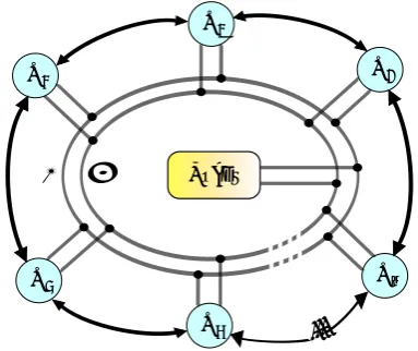
A Microgrid can be represented as a set of nodesNi i=
1, ... nas in Figure (4). Each node is twofold connected to its neighbors, thus forming a two layer network: the first layer provides to power exchange and the second one for information data flow.
Within the information layer, each node can exchange data only with its neighbors, which depends on how the information network topology has been realized, spreading messages and data packets about its state
N1
N4
-+
...
Loads N2
N3
N5
Nm
Figure 4. Microgrid: grey lines represent Power Grid, black arrows represent Information Network, circles represent nodes.
and updating it according to the received informations. Every node includes the energy source, the power converter and the Agent Control Unit (ACU), as shown in Figure (5). A synchronization process is required in order to obtain a common phase for all signals in order to get a good operation of the MG.
3.2. The agent
A typical ACU is featured by the following properties:
1. it is resident in a specific node
2. it is capable to send/receive data informations about its internal/external state and to act locally through a control scheme
3. it can interact only with a certain number of adjacent agents, according to the MG information network topology
4. it is modeled by a first-order dynamic system, whose initial state is determined by local data detected by the agent itself. Each single dynamic is mutually coupled with the nearby dynamics by a proper local coupling law, or better, by a consensus algorithm.
Energy
Source Converter
Agent Control
Unit
N
iMicro Grid Power Connection
Micro Grid Information Connection
Figure 5. The generic nodeNi and its subsystems: the energy source, the power converter and the ACU.
(i.e., monitoring, control and time synchronization) can be performed according to a decentralized and self-organized computing framework.
3.3. Mathematical model: the Consensus Algorithm
In the proposed model, each agent is equipped with its own clock and the consensus algorithm resides on the agent itself, i.e. the ACU shown in Figure (5). The clock evolutionξi(t) provides the dynamic of a single
agent; a synchronization among different agents is reached when all of them perform the same dynamics. Neglecting second order terms and stochastic effects, ξi(t) is given by [64]:
ξi(t) =αi+βit i= 1, ... n (4)
whereαi andβiare the skew and the offset coefficients,
respectively,tis the absolute time andnis the number of agents. In order to estimate these coefficients, the Average Time Synchronization (ATS) algorithm [64] is used. The goal of this algorithm is to obtain informations regarding the clock coefficients of theith agent dynamic, processing the time offsets with its neighbors and synchronizing the agents dynamics to a virtual reference clockξv(t) to which each agent has to
converge:
ξv(t) =αv+βvt (5)
The exact values of the two coefficientsαv and βv are
not important and depends on the initial conditions, so they may change according to them. During the consensus process, each agent has a local estimate of the virtual reference clock ˆξv,i(t):
ˆ
ξv,i(t) = ˆoi+ ˆsiξi(t) i= 1, ... n (6)
In [64], it is demonstrated that the convergence is reached when:
lim
t→+∞ ˆ
ξv,i(t) =ξv(t) i= 1, ... n (7)
where ˆsi and ˆoi are the local parameter estimations of
the skew and offset, respectively, relatively to the time
ξi(t). These parameters must be given to the ith local
clock ξi(t) in order to compensate its difference with
the virtual reference clock ˆξv,i(t).
Substituting Equation (4) in Equation (6), the following non linear equation is obtained:
ˆ
ξv,i(t) = ˆoi+ ˆsiαi+ ˆsiβit i= 1, ... n (8)
ATS consensus algorithm estimates the relative speed βij =
βj
βi of the i
th clock respect its jth neighbor.
Denotingtkthe time when theithagent receives a
time-stampξj(tk) from thejthagent, the pair
h
ξi(tk), ξj(tk)
i
is recorded by the ith agent in its own memory. When a second information packet arrives and a second pair
h
ξi(tk+1), ξj(tk+1)
i
is recorded, the following parameter is evaluated by theithagent:
µij(tk+1) =λµµij(tk) +
1−λµξj(tk+1)
−ξj(tk)
ξi(tk+1)−ξi(tk)
(9)
whereµij(tk) represents the estimation of the relative
clock speed between theith andjthclock at the timetk.
The initial conditionµij(0) =µ0is given andλµ∈(0,1)
is a tunable parameter. It is shown in [64] that:
lim
k→+∞µij(tk) =βij i, j= 1, ... n (10)
In order to estimate ˆsiand ˆoi, useful to the Equation (6),
the following relations are used:
ˆ
si(tk+1) =λωsˆi(tk) +
+ (1−λω)µij(tk) ˆsj(tk) i, j= 1, ... n (11)
ˆ
oi(tk+1) = ˆoi(tk) + (1−λ0)
ˆ
sj(tk)ξj(tk) + ˆoj(tk)−
−sˆi(tk)ξi(tk)−oˆi(tk)) i, j= 1, ... n
(12)
where λω∈(0,1) and λ0∈(0,1) are tunable parame-ters.
In [64] is proved that:
lim
t→+∞sˆi(t)βi =βv i= 1, ... n (13)
lim
t→+∞ oˆi(t) + βv
βi
αi
!
=αv i= 1, ... n (14)
where it is possible to define the auxiliary parameters:
ˆ
si(t)βi =Ωi
ˆ
oi(t) +ββviαi =Θi
i= 1, ... n (15)
used in the Figures shown in next section. So, the information packet of theithagent is given by the local
When each agent has got, for its own clock, the same reference virtual clock dynamic, the virtual time ξv is common to all agents and, consequently, a
synchronization is reached. When all clock dynamics ξi(t) i= 1, ... nhave been synchronized withξv, all
generic functions depending on ξv are, consequently
synchronized [65].
Pulse Width Modulation (PWM) is a typical modula-tion technique for low/medium power converters[66]. In this paper, the main duty of ACU is feed PWM unit toward synchronization. Carrier waveformη per-forming modulation, represents the function to be syn-chronized. A triangular carrier waveform (TCW) with period 2aand amplitude fromAto−A, can be expressed as:
η(ξv) =A·2
a
ξv−
ξ
v
a + 1 2
a
(−1)
jξv
a−12 k
(16)
where the operator
f
is thefloor functionoff.
Since each agent acts as a header emitting its own status information packets to the neighboring agents, the consensus, or better the synchronization, is obtained without the need of any cluster header or centralized supervisory structure.
4. System implementation
This section shows system implementation. Three distinct configurations have been considered for system’s simulation with Matlab/Simulinkr.
4.1. Two node case
Two distinct generators, i.e. nodes, have been consid-ered, each one consisting of 5-level cascaded multilevel H-bridge converter (see Figure (6)). At this level of abstraction, the influence of the electric loads can be neglected and the attention can be focused on the information layer only. Moreover, the delay in com-munication networktdel can be assumed symmetrical, thus the information propagation time between nodes N1andN2can be assumed equal in both directions (N1 -N2) and (N2-N1).
As shown in Figure (6a), each node DG includes two DC power sourcesVdc. The ACU block is represented in
Figure (7), where it is possible to identify eight PWM signalsINxy,x= 1,2,3,4 andy= 1,2 produced by the
ACU and used as shown in Figure (6b).
Converter output is the result of the application of modulation patterns generated by ACU, the latter could be realized using a very large scale integration component (VSLI), for instance a Field Programmable Gate Array (FPGA) or one or multiple micro-controllers [67]. In the considered case, ACU includes
V
dcV
dcIN1 1
A
1B
1A
2B
2H-Bridge
1H-Bridge
2IN1 2
IN1 3 IN
1
4 IN
2 4 IN
2 3
IN2 2
IN2 1
Micro Grid Power Connection
Micro Grid Information Connection
Energy Source
Converter
Agent Control
Unit
Node
(a)Cascaded H-bridge 5-level converter.
S
1S
2S
3S
4G
G
G>1 (Gain) IN1
3
IN1 1
Vdc
A1
B1 G
IN1 2
G IN1
4
H-Bridge1
(b)Detail of H-Bridge1.
Figure 6. Cascaded H-bridge multilevel converter description.
-+
Shared Memory
Unit
Communication Microprocessor
PWM Unit
Converter
Energy Source
Consensus Algorithm Microprocessor
MicrowGrid
InformationwNetwork
Agent ControlwUnit
Node
H-Bridge
1H-Bridge
2Figure 7. The ACU detail.
• data packets arrive from the Agent Network (AN) to the Communication Microprocessor (CM), bringing information from that particular agent who sent the package
• CM places informations inside the SMU, available for the Consensus Algorithm Microprocessor (CAM)
• CAM picks the external network informations from the SMU and executes the consensus algorithm also with its status informations
• the output of the consensus algorithm is used in order to give the right parameters to the PWMU, to synthesize properly the PWM signal to drive the converter
• the result of the consensus algorithm is also placed inside the SMU, available for the CM
• finally, the CM picks the new status informations of the agent from the SMU and sends them to the AN, so that another agent will perform the same steps.
At this stage, agents have been developed by using Matlab/Simulinkr and implementing the blocks CM, CAM and PWMU, as shown in Figure (8).
1. CM block: this block receives data packetspkgExt
from the AN, stores these informations inside the SMU, and then sends the internal data packet
pkgInt to the AN. Packets pkgExt and pkgInt
are vectors with three parameters [ξh,sˆh,oˆh]
supplied to the external (h=j) and internal (h=i)
Communication Microprocessor
Consensus Algorithm Microprocessor
PWM Unit pkgExt
nslot
pkgInt
nslot div
lambda pkgParam pkgParamExt pkgParamNC
tabs
pkgParamNC pkgExt
1 pkgInt
pwmSignals nslot
div
[1x3] RAMS Memory
slot
Clock Divisions
Lambda Filters
tabs
pkgParamExt
pkgParam
PWM Signals
2 1
Figure 8. The single Agent developed in Matlab/Simulinkr.
agent, respectively. Furthermore, there is a third parameterRAM Memory Slot (nslot)representing the number of information packets stored inside the SMU, both in Input or Output direction, i.e. a buffer memory.
2. CAM block: this block takes pkgExt parameters
from SMU, executes the consensus algorithm with internal and external clock informations, places results inside the SMU through pkgInt and then gives directives through the parameters
pkgParamNC,tabs,pkgParamExt andpkgParamto
the PWMU. The input parameters of this block
are: nslot, Clock Divisions (div) and Lambda
Fil-ters hλµ, λω, λ0
i
. The Clock Divisions parameter controls the frequency of time-stamps extrac-tion from the clock dynamic, the Equaextrac-tion (4).
TheLambda Filters represent three λparameters
defined in Equations (9), (11) and (12), respec-tively, which control the convergence of the con-sensus algorithm.
3. PWMU block: this block generates output PWM
signals. It receives directives from the CAM block through the input parameterspkgParamNC,
tabs,pkgParamExtandpkgParam, then returns the
vector pwmSignlas, which consists of the eight componentsINxy,x= 1,2,3,4 andy= 1,2.
Table (1) shows two distinct parameter configurations used during simulations. These values are considered the same for both agents.
(a)Withtdel= 0s.
(b)Withtdel= 10−4s.
Figure 9. Clock skew convergence behaviors of the two nodes.
configurations, the system convergence is reached in less than 2 ms.
In this test PWM is implemented by using a TCW operating at f1= 310 kHz and at f2= 210 kHz, respectively, for the two agents, in both delay times tdel. After clocks convergence, the TCW frequency is the same for both the agents, in particularfv= 265 kHz
for tdel= 0s and fv= 280 kHz for tdel= 10
−4 s. As modulating signal, a fixed value comparator comp= 0.8 has been used. Figures (11) and (12) show the TCW and a pulse pattern, respectively, for the two agents, at different delay times. In particular in Figure (12) a single PWM signal is reported, among the eight available. It is imposed that the clocks compensation happens at 6 ms and consequently the two TCW are overlapped. The compensation time value is arbitrarily chosen, but in any case, it is longer than the time required for the mathematical convergence shown in Figures (9) and (10). In these figures it can be seen that after the compensation time, i.e. after agents’ synchronization, the TCW and the PWM signal of the nodes are overlapped. The consequence is that the electric signal produced by the two converters are synchronized inside the MG, because the PWM
Table 1. System parameters configurations.
Mode nsolt div λµ λω λ0 tdel(s)
Config 1 5 10 0.1 0.8 0.5 0
Config 2 5 10 0.1 0.8 0.5 0.0001
(a)Withtdel= 0s.
(b)Withtdel= 10−4s.
Figure 10. Clock offset convergence behaviors of the two nodes.
signals of each node drive their associated H-bridges semiconductor devices, synchronously respect to the other node.
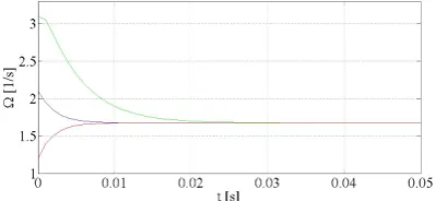
4.2. Three node case
In this case, the considered MG consists of three DGs, therefore the system includes three nodesN1,N2 and N3. For each node the 5-level converter has been adopted, as described in section4.1.
As in the previous paragraph, power issues are neglected and the attention is focused just on the information layer. The network communication delay timetdelis assumed symmetric also here, which means that the information propagation time between the three nodesN1,N2andN3 is equal in every directions. The information topology network is realized linking nodeN1to nodeN2and vice versa, and nodeN1to node N3 and vice versa. No direct information connections are realized between nodes N2 and N3. This means that the influence of N2 on N3 passes only through the N1 informations. This is the base of the principle think locally, act globally. All the system configuration set considered in the previous section is replicated in this case, both for hardware, software, parameters and algorithm point of view. Below are shown just some of the simulated characteristic trends.
Figures (13) and (14) report the behaviors of the main system parameters in this configuration, with a delay information propagation time tdel = 10−4
(a)Withtdel= 0s.
(b)Withtdel= 10−4s.
Figure 11. The PWM modulation waveform convergence behaviors of the two nodes.
of a third node increases the convergence time of system dynamics. In Figure (13b) is shown the dynamic of each single clock. It is evident the convergence behavior of the three clocks to a common linear trend.
In Figure (14) is reported the TCW convergence, used for the PWM. In this case clock compensation occur at 80 ms, resulting three overlapped TCW. As in the paragraph before, the compensation time value is arbitrarily chosen, but in any case, it is greater than the time required for the mathematical convergence shown in Figures (13a) and (13b). Similar conclusions to the previous paragraph can be deduced from the three clocks synchronization behaviors. The overlap of the three TCW after the compensation time imply the synchronization of the three converter electric signal inside the MG.
(a)Withtdel= 0s.
(b)Withtdel= 10−4s.
Figure 12. The PWM signal convergence behaviors of the two nodes.
4.3. Six node case
Here six DGs are considered in the MG, therefore the system includes six nodes N1, N2, N3, N4, N5 and N6. Also here, for each node the 5-level converter has been adopted, as described in sections 4.1 and 4.2. The attention is always focused on the information layer and the network communication delay time tdel is assumed symmetric. In this case, two information network topology are considered. In Figure (15) are reported the two information network. Figure (15a) shows a sort of centralized topology where every node has a bi-directional connection only with the nodeN1, which behaves as a information hub. Figure (15b), on the other hand, shows a decentralized network with two cluster of three nodes, connected only by a bi-directional connection between the two nodes N1 and N2.
(a)The three clocks skew convergence, withtdel= 10−4s
(b)The three clocks convergence dynamics, withtdel= 10−4s. Figure 13. The clocks behavior of the three nodes.
Figure 14. The PWM modulation waveform signals of the three nodes, withtdel= 10−4s
propagation time tdel = 10−4s. In Figures (16a) and (18a) is possible to see the skew convergence of the six nodes respectively for the centralized and decentralized topology. Also here, the presence of more nodes increases the convergence time of system dynamics. In Figures (16b) and (18b) are shown the dynamic of each single clock respectively for the centralized and decentralized topology. Again, is evident the convergence behavior of the six clocks to a common linear trend in both cases.
The analysis in six node configuration opens to broader considerations and issues for a Ni i= 1, . . . n nodes
system. The most important and evident consequence,
N
1N
4N
2N
3N
5N
6(a)The centralized network topology.
N
1N
4N
6N
3N
5N
2(b)The decentralized network topology.
Figure 15. The two topology considered for the six node case.
is that the convergence time lengthens, because a higher number of agents must be mediated. This problem could be further investigated tuning the div and
Lambda Filtershλµλω, λ0
i
agents parameters, searching the optimal configuration set which minimize the convergence time. The information network topology is also another aspect to consider. Both these observations depends according to the number of agents inside the network. Being connected to particular nodes could accelerate the convergence. These nodes are known as hubs, or better the nodes which collect the largest number of connections with other nodes. In scientific literature this behavior is know as the
preferential attachmentlogic [69]. Furthermore a cluster
(a)The six clocks skew convergence, withtdel= 10−4s
(b)The six clocks convergence dynamics, withtdel= 10−4s. Figure 16. The clocks behavior of the six nodes with centralized topology.
Figure 17. The PWM modulation waveform signals of the six node with centralized topology, withtdel = 10−4s
4.4. Communication specifications
An implementation of the system described in section
3 is possible nowadays, thanks to the improvements of the ICT, and several communication protocols have been developed. The attention must be focused on one aspect in particular, the communication protocol, through which the agent’s informations flow. The choice, made in this paper, falls on the communication protocol Field-bus. The reason is because this is a particular industrial computer network protocol realized for real-time distributed control, standardized as IEC 61158 [70]. This protocol possesses advantages that well fit the system modeled, including flexible and scalable architecture; therefore, addition of new modules or integration of new functions is always possible without affecting existing wiring. The implementation of a network based on the proposed
(a)The six clocks skew convergence, withtdel= 10−4s
(b)The six clocks convergence dynamics, withtdel= 10−4s. Figure 18. The clocks behavior of the six nodes with decentralized topology.
Figure 19. The PWM modulation waveform signals of the six node with decentralized topology, withtdel= 10−4s
technology corresponds to realization of a Local Area Network (LAN) resulting low impact, because of the well-known and inexpensive technology.
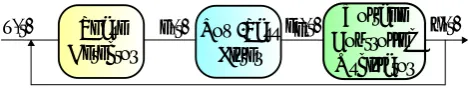
Following the Open Systems Interconnection (OSI) model ISO/IEC 7498-1 [71], the Field-bus functional model for communication is made of three levels, as show in Figure (20). In the Application layer resides those informations exchanged between the agents, organized in packets. This means that each agent’s CM must be equipped with a peripheral able to generate informations packets, which satisfy the Field-bus protocol.
Application Layer
Data Link Layer
Physical Layer
Figure 20. Field-bus functional layers.
transfers data between adjacent network nodes. Other Field-bus protocols are possible on different Data Link layer such as Token and SDLC.
5. Conclusions
In this paper a synchronization technique, based on the MAS approach, for a group of DGs inside a MG, has been proposed. A review of synchronization methods both for DGs in power grid and distributed systems is reported. Then, a description on how the system hardware architecture is given and system simulation results are shown primarily for a simple configuration of two agents, secondly for three agents and then for six agents. The ATS consensus algorithm has been applied and simulation results have been obtained.
The advantages of the proposed methodology are:
• it does not require voltage and current measure-ments, since the synchronization data travel on a different layer dedicated to the information exchanges, see Figure (4)
• it does not require a reference power signal inside the MG, so it is suitable for isolated MG without a connection to the main national power grid
• it is scalable, flexible and resilient, in fact it is automatically reconfigured if some DGs are excluded or added into the MG
• it represents a new synchronization technique which requires a new standard.
Ideally, this new technique creates an open-loop method, because all the measurements of the voltages and currents, required by the traditional synchroniza-tion methods such as the PLL [43,46], are eliminated. Anyway, the open-loop hypothesis is certainly ideal and must be proved. It is evident that the quality of the information network is an important parameter, which must ensure the synchronization task with precision and speed.
Future work will focus its attention on the effect of i) the topology of the DGs information networkii) the effect of loads inside the MG. A more detailed study on the influence of delay time propagation could be performed, in order to find the parameters which help to optimize the convergence. Finally the proposed algorithm could be implemented on a real MG, with two or more control boards on which develop the code, in order to synthesize the synchronized PWM signals.
References
[1] Yu, X., Cecati, C., Dillon T. and M. G. Simoes (2011) The new Frontier of Smart Grids.IEEE Ind. Electron. Mag.5(3): 49-63.
[2] Rogers, K. M. et al. (2010) An Authenticated Control Framework for Distributed Voltage Support on the Smart Grid.IEEE Trans. Smart Grid1(1): 40-47.
[3] Aquino-Lugo, A.A., Klump, R. and Overbye, T.J. (2011) A Control Framework for the Smart Grid for Voltage Support Using Agent-Based Technologies.IEEE Trans. Smart Grid2(1): 173-180.
[4] Meliopoulos, A.P.S. et al. (2011) Smart Grid Technologies of Autonomous Operation and Control.IEEE Ind. Electron. Mag.2(1): 1-10. [5] Arnold, G.W. (2011) Challenges and
Opportuni-ties in Smart Grid: A Position Article.Proc. IEEE.
99(6): 922-927.
[6] Cossent, R., Gómez, T. and Frías, P. (2009) Towards a future with large penetration of dis-tributed generation: Is the current regulation of electricity distribution ready? regulatory rec-ommendations under a European perspective.
Energy Policy37(3): 1145-1155.
[7] Joskow, P.L. (2008) Lessons learned from electricity market liberalization.Energy Journal
29: 9.
[8] Carrasco, J.M. et al. (2006) Power-Electronics Systems for the Grid Integration of Renewable Energy Sources: A Survey. IEEE Trans. Ind. Electron.53(4): 1002-1015.
[9] Strasser, T. et al. (2014) A Review of Architec-tures and Concepts for Intelligence in Future Electric Energy Systems.IEEE Trans. Ind. Elec-tron.62(4): 2424-2438.
[10] Güngör, V.C. et al. (2011) Smart Grid Technolo-gies: Communication Technologies and Stan-dards.IEEE Trans. Ind. Informat.7(4): 529-539. [11] Sauter, T. and Lobashov M. (2011) End-to-End
Communication Architecture for Smart Grid.
IEEE Trans. Ind. Electron.58(4): 1218-1228. [12] Lasseter, R.H. (2002) Microgrids IEEE Power
Engineering Society Winter Meeting1: 305-308. [13] Khodaei, A. (2014) Provisional Microgrids.IEEE
Trans. Smart GridPP(99): 1-9.
Power Line Communications in the Smart Grid.
Proc. IEEE99(6): 998-1027.
[15] Luck, M., Marik, V., Štrpánková, O. and Trappl, R. (2001) Multi-Agent Systems and Applications
(Berlin Springer-Verlag).
[16] Cao, Y., Yu, W., Ren, W. and Chen, G. (2013) An overview of recent progress in the study of distributed multi-agent coordination. IEEE Trans. Ind. Informat.9(1): 427-438.
[17] Leitão, P., Mařík, V. and Vrba, P. (2013) Past, present, and future of industrial agent applications. IEEE Trans. Ind. Informat. 9(4): 2360-2372.
[18] Loia, V., Vaccaro, A. and Vaisakh, K. (2013) A self-organizing architecture based on coopera-tive fuzzy agents for smart grid voltage control.
IEEE Trans. Ind. Informat.9(3): 1415-1422. [19] Islam, S.R., Muttaqi, K.M. and Sutanto, D.
(2014) Multi-agent receding horizon control with neighbour-to-neighbour communication for prevention of voltage collapse in a multi-area power system.Generation, Transmission and Distribution, IET8(9): 1604-1615.
[20] Vrba, P. et al. (2014) A Review of Agents and Service-Oriented Concepts Applied to Intelligent Energy Systems. IEEE Trans. Ind. Informat.10(3): 1890-1903.
[21] Aquino-Lugo, A.A., Klump, R. and Overbye, T.J. (2011) A Control Framework for the Smart Grid for Voltage Support Using Agent-Based Technologies Angel.IEEE Trans. Smart Grid2(1): 173-180.
[22] Nagata, T. and Okamoto, K. (2014) A decentral-ized distribution power system restoration by using multi-agent Approach. In Proceedings of the International Electrical Engineering Congress
(Chonburi, Thailand, iEECON), 1-4.
[23] Fenghui, R., Minjie, Z. and Sutanto, D. (2013) A Multi-Agent Solution to Distribution System Management by Considering Distributed Gener-ators.IEEE Transactions on Power Systems28(2): 1442-1451.
[24] Yao, C., Jinhu, L., Xinghuo, Y. and Hill, D.J. (2013) Multi-Agent Systems with Dynamical Topologies: Consensus and Applications. IEEE Circuits and Systems Magazine13(3): 21-34. [25] Nagliero, A., Mastromauro, R.A., Liserre, M.
and Dell’Aquila, A. (2010 Monitoring and Synchronization Technniques for Single-Phase PV Systems. In Proceedings of the International Symposium on Power Electronics Electrical Drives Automation and Motion(Pisa, Italy, SPEEDAM), 1404-1409.
[26] Timbus, A., Liserre, M., Teodorescu, R. and Blaabjerg, F. (2005) Synchronization methods for three phase distributed power generation systems - An overview and evaluation. In Pro-ceedings of the IEEE Power Electronics Specialists Conference(Recife, Brazil, PESC), 2474-2481. [27] Valiviita, S. (1999) Zero-crossing detection of
distorted line voltages using 1-b measurements.
IEEE Trans. Ind. Electron.46(5) : 917-922. [28] Svensson, J. (2001) Synchronization methods
for grid-connected voltage source converters.
IEEE Proceedings-Generation, Transmission and Distribution148(3): 229-235.
[29] Karimi-Ghartemani, M. and Iravani, M.R. (2004) A method for synchronization of power electronic converters in polluted and variable-frequency environments. IEEE Transactions on Power Systems19(3): 1263-1270.
[30] Lee, T.H. (2003) The Design of CMOS Radio-Frequency Integrated Circuits (Cambridge Uni-versity Press).
[31] Pan, C.T. and Fang, E. (2008) A phase-locked-loop-assisted internal model adjustable speed controller for BLDC motors. IEEE Trans. Ind. Electron.55(9): 3415-3425.
[32] Chen, M.P. et al. (2001) Surge analysis of induction heating power supply with PLL.IEEE Trans. Power Electron.16(5): 702-709.
[33] Kesler, M. and Ozdemir, E. (2011) Synchronous-Reference-Frame-Based Control Method for UPQC Under Unbalanced and Distorted Load Conditions. IEEE Trans. Ind. Electron. 58(9): 3967-3975.
[34] Ciobotaru, M., Teodorescu, R. and Blaabjerg, F. (2006) A New Single-Phase PLL Structure Based on Second Order Generalized Integrator. In Proceedings of the IEEE Power Electronics Specialists Conference(Jeju, South Korea, PESC), 1-6.
[35] Escobar, G. et al. (2011) Fixed-reference-frame phase-locked loop for grid synchronization under unbalanced operation. IEEE Trans. Ind. Electron.58(5): 1943-1951.
[36] Ziariani, A.K. and Konrad, A. (2004) A method of extraction of non-stationary sinusoid.Signal Processing84(8): 1323-1346.
[37] Ferreira, R.J., Araújo, R.E. and Peças Lopes, J.A. (2011) A Comparative Analysis and Imple-mentation of Various PLL Techniques Applied to Single-phase Grids. In Proceedings of the 3rd International Youth Conference on Energetics
(Budapest, Hungary, IYCE), 1-8.
[38] Rodriguez, P. et al. (2007) Decoupled Double Synchronous Reference Frame PLL for Power Converters Control.IEEE Trans. Power Electron.
22(2): 584-592.
[39] Wang, Y. and Li, Y. (2011) Grid synchronization PLL based on cascaded delayed signal cancel-lation.IEEE Trans. Power Electron.26(7): 1987-1997.
[40] Rodriguez, P. et al. (2006) Advanced grid syn-chronization system for power converters under unbalanced and distorted operating conditions. In Proceedings of the IEEE Annual Conference on Industrial Electronics(Paris, France, IECON), 5173-5178.
IEEE Trans. Ind. Appl.49(6): 2709-2719.
[42] Hadjidemetriou, L., Kyriakides, E. and Blaab-jerg, F. (2014) An Adaptive Tuning Mechanism for Phase-Locked Loop Algorithms for Faster Time Performance of Interconnected Renewable Energy Sources. IEEE Trans. Ind. Appl.51(2): 1792-1804.
[43] Hadjidemetriou, L., Kyriakides, E. and Blaab-jerg, F. (2015) A Robust Synchronization to Enhance the Power Quality of Renewable Energy Systems.IEEE Trans. Ind. Electron.62(8): 4858-4868.
[44] Zhong, Q.C. and Weiss, G. (2011) Synchronvert-ers: Inverters That Mimic Synchronous Genera-tors.IEEE Trans. Ind. Electron.58(4): 1259-1267. [45] Zhong, Q.C. and Nguyen, P.L. (2012) Sinusoid-locked loops based on the principles of syn-chronous machines. InProceedings of the Chinese Control and Decision Conference(Taiyuan, China, CCDC), 1518-1523.
[46] Zhong, Q.C. and Hornik, T. (2013) Control of Power Inverters in Renewable Energy and Smart Grid Integration(Academic Press).
[47] Chandorkar, M.C (1993) Control of parallel connected inverters in standalone AC supply systems.IEEE Trans. Ind. App.29(1): 136-143. [48] Li, L., Benliang, L. and Houjun, W. (2010) Clock
Synchronization of Wireless Distributed System Based on IEEE 1588. InProceedings of the Cyber-Enabled Distributed Computing and Knowledge Discovery (Huangshan, China, CyberC), 205-209.
[49] Cheng-I, C. (2013) A Phasor Estimator for Synchronization Between Power Grid and Dis-tributed Generation System. IEEE Trans. Ind. Electron.60(8): 3248-3255.
[50] Yang, T., Huijun, G., Wei, Z. and Kurths, J. (2013) Distributed Synchronization in Networks of Agent Systems With Non-linearities and Random Switchings. IEEE Trans. Cyber., 43(1): 358-370.
[51] Cena, G. et al. (2013) Synchronize your watches: Part 1.IEEE Ind. Electron. Mag.7(1): 18-29. [52] Cena, G. et al. (2013) Synchronize your watches:
Part 2.IEEE Ind. Electron. Mag.7(2): 27-39. [53] Mills, D.L. (1991) Internet time
synchroniza-tion: the network time protocol. IEEE Trans. Comm.39(10): 1482-1493.
[54] National Institute of Standards and Technology, IEEE 1588 Web Site. http://www.nist.gov/ el/isd/ieee/ieee1588.cfm (accessed on 30 November 2015).
[55] Lee, S. and Hong, C. (2012) An Accuracy Enhanced IEEE 1588 Synchronization Protocol for Dynamically Changing and Asymmetric Wireless Links. IEEE Communications Letters
16(2): 190-192.
[56] Holler, R., Sauter, T. and Kero, N. (2003) Embedded SynUTC and IEEE 1588 clock synchronization for industrial Ethernet. In
Proceedings of the IEEE Conference Emerging Technologies and Factory Automation (Lisbon, Portugal, ETFA): 422-426.
[57] Fan, L., Chen Z. and Zhao, C. (2011) The analy-sis of Clock Synchronization Protocol on Ether-net. InProceedings of the International Conference Remote Sensing, Environment and Transportation Engineering(Nanjing, China, RSETE), 826-829. [58] Steiner, W. (2008) TTEthernet Specication
TTTech Computertechnik AG, SchÃűnbrunner Strasse 7, 1040 Vienna, Austria, 0.9.1 edition. [59] GPS Web Site. http://www.gps.gov (accessed
on 30 November 2015).
[60] GLONASS Web Site. http://www. glonass-ianc.rsa.ru (accessed on 30 November 2015).
[61] GALILEO Web Site. http://ec.europa.eu/ growth/sectors/space/galileo/index_en. htm(accessed on 30 November 2015).
[62] Olifati-Saber, R., Fax, J.A. and Murray, R.M. (2007) Consensus and Cooperation in Net-worked Multi-Agent Systems.Proc. IEEE95(1): 215-233.
[63] Barbarossa, S. and Scutari, G. (2007) Decentral-ized maximum likelihood estimation for sen-sor networks composed of non-linearly coupled dynamical systems. IEEE Trans. Signal Process
55(7): 3456-3470.
[64] Schenato, L. and Fiorentin, F. (2011) Average TimeSynch: A consensus based protocol for clock synchronization in wireless sensor net-works.Automatica47: 1878-1886.
[65] Vaccaro, A. et al. (2015) A Self-Organizing Architecture for Decentralized Smart Micro-grids Synchronization.IEEE Trans. Ind. Informat.
11(1): 289-298.
[66] Rashid, M.H. (2013)Control of Power Inverters in Renewable Energy and Smart Grid Integration(J. Wiley& Sons Ltd Publication IEEE Press). [67] Buccella, C., Cecati, C. and Latafat H. (2012)
Digital Control of Power Converters-A Survey.
IEEE Trans. Ind. Informat.8(3): 437-447. [68] Texas Instruments. http://www.ti.com/
lsds/ti/microcontrollers_16-bit_32-bit/ c2000_performance/control_automation/ f28m3x/overview.page (accessed on 28 November 2015).
[69] Giammatteo, P., Donato, D., Zlatić, V. and Cal-darelli, G. (2010) A PageRank-based preferential attachment model for the evolution of the World Wide Web.Euro Physics Letters91(1): 18004. [70] International Electrotechnical Commission. IEC
WebStore. https://webstore.iec.ch/home
(accessed on 25 August 2015).
[71] International Organization for Standardization. OSI Model ISO/IEC 7498-1. http: //standards.iso.org/ittf/licence.html
(accessed on 25 August 2015).